check engine JAGUAR XJ6 1994 2.G Electrical Diagnostic Manual
[x] Cancel search | Manufacturer: JAGUAR, Model Year: 1994, Model line: XJ6, Model: JAGUAR XJ6 1994 2.GPages: 327, PDF Size: 13.73 MB
Page 157 of 327
E I ect r ical
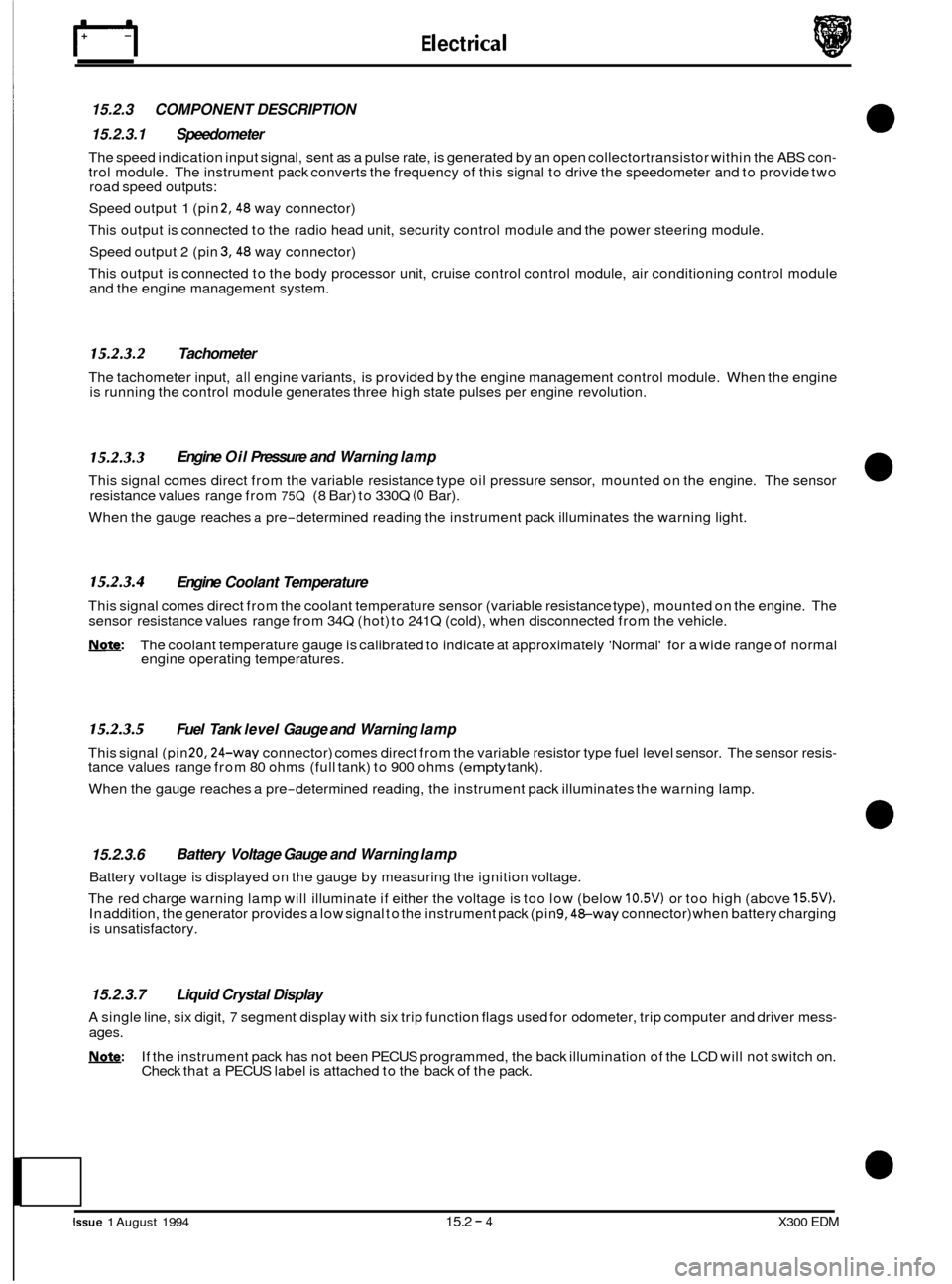
15.2.3 COMPONENT DESCRIPTION
15.2.3.1 Speedometer
The speed indication input signal, sent as a pulse rate, is generated by an open collectortransistor within the ABS con- trol module. The instrument pack converts the frequency of this signal to drive the speedometer and to provide two
road speed outputs:
Speed output
1 (pin 2,48 way connector)
This output is connected to the radio head unit, security control module and the power steering module.
Speed output 2 (pin
3,48 way connector)
This output is connected to the body processor unit, cruise control control module, air conditioning control module
and the engine management system.
15.2.3.2 Tachometer
The tachometer input, all engine variants, is provided by the engine management control module. When the engine
is running the control module generates three high state pulses per engine revolution.
15.2.3.3
This signal comes direct from the variable resistance type oil pressure sensor, mounted on the engine. The sensor
resistance values range from 75Q (8 Bar) to 330Q (0 Bar).
When the gauge reaches
a pre-determined reading the instrument pack illuminates the warning light.
Engine Oil Pressure and Warning lamp
15.2.3.4 Engine Coolant Temperature
This signal comes direct from the coolant temperature sensor (variable resistance type), mounted on the engine. The
sensor resistance values range from 34Q (hot) to 241Q (cold), when disconnected from the vehicle.
Note: The coolant temperature gauge is calibrated to indicate at approximately 'Normal' for a wide range of normal
engine operating temperatures.
15.2.3.5 Fuel Tank level Gauge and Warning lamp
This signal (pin 20,24-way connector) comes direct from the variable resistor type fuel level sensor. The sensor resis- tance values range from 80 ohms (full tank) to 900 ohms (empty tank).
When the gauge reaches a pre
-determined reading, the instrument pack illuminates the warning lamp.
15.2.3.6
Battery voltage is displayed on the gauge by measuring the ignition voltage.
The red charge warning lamp will illuminate if either the voltage is too low (below
10.5V) or too high (above 15.5V). In addition, the generator provides a low signal to the instrument pack (pin 9,48-way connector) when battery charging
is unsatisfactory.
Battery Voltage Gauge and Warning lamp
15.2.3.7 Liquid Crystal Display
A single line, six digit, 7 segment display with six trip function flags used for odometer, trip computer and driver mess- ages.
!Y,Q&: If the instrument pack has not been PECUS programmed, the back illumination of the LCD will not switch on.
Check that a PECUS label is attached to the back of the pack.
Issue 1 August 1994 15.2 - 4 X300 EDM
Page 160 of 327
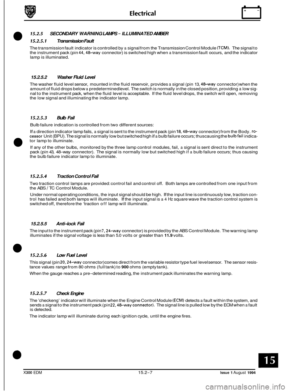
15.2.5 SECONDARY WARNING LAMPS - ILLUMINATED AMBER
15.2.5.1 Transmission Fault
The transmission fault indicator is controlled by a signal from the Transmission Control Module (TCM). The signal to
the instrument pack (pin 44,48-way connector) is switched high when a transmission fault occurs, and the indicator
lamp is illuminated.
15.2.5.2 Washer Fluid Level
The washer fluid level sensor, mounted in the fluid reservoir, provides a signal (pin 13, 48-way connector) when the
amount of fluid drops below a predetermined level. The switch is normally in the closed position, providing a low sig-
nal to the instrument pack, when the fluid level is acceptable. If the fluid level drops, the switch will open, removing
the low signal and illuminating the indicator lamp.
15.2.5.3 Bulb Fail
Bulb failure indication is controlled from two different sources:
If a direction indicator lamp fails, a signal is sent to the instrument pack (pin 18,48-way connector) from the Body. :o- cessor Unit (BPU). The signal is normally low but switched high if a bulb failure occurs; thuscausing the bulbfail indica-
If any of the other bulbs, monitored by the three lamp control modules, fail, a signal is sent direct to the instrument
pack (pin 43, 48-way connector). The signal is normally low but switched high if a bulb failure occurs; thus causing
the bulb failure indicator lamp to illuminate.
tor lamp to illuminate.
15.2.5.4 Traction Control Fail
Two traction control lamps are provided: control fail and control off. Both lamps are controlled from one input from
the ABS / TC Control Module.
Under normal operating conditions, the input signal should be high.
If the input line is continuously low, traction con- trol has failed and both lamps will illuminate. If the input signal is a 4 Hz square wave the traction control system is
switched off, therefore the ‘traction off lamp will illuminate.
15.2.5.5 Anti-lock Fail
The input to the instrument pack (pin 7,24-way connector) is provided by the ABS Control Module. The warning lamp
illuminates if the signal voltage is less than 5.0 volts or greater than 11.9 volts.
- 15.2.5.6 Low Fuel Level
This signal (pin 20,24-way connector) comes direct from the variable resistor type fuel level sensor. The sensor resis-
tance values range from 80 ohms (full tank) to 900 ohms (empty tank).
When the gauge reaches
a pre-determined reading, the instrument pack illuminates the warning lamp.
15.2.5.7 Check Engine
The ’checkeng’ indicator will illuminate when the Engine Control Module (ECM) detects a fault within the system, and
sends a signal to the instrument pack (pin 22,48-wayconnector). The signal line is pulled low by the ECM when a fault
is detected.
The indicator lamp will illuminate during each ignition cycle, until the engine fires.
X300 EDM 15.2-7 Issue 1 August 1994
Page 163 of 327
rl E I ect r ica I
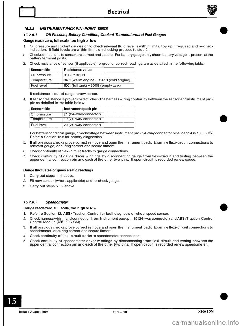
15.2.8 INSTRUMENT PACK PIN-POINT TESTS
15.2.8.1 Oil Pressure, Battery Condition, Coolant Temperature and Fuel Gauges
Gauge reads zero, full scale, too high or low
1.
2.
3. Oil
pressure and coolant gauges only; check relevant fluid level is within limits, top up if required and re-check
indication. If fluid levels are within limits on checking proceed to step 2.
Check connections to sensor are correct and secure. For battery gauge only check battery voltage is present at the
battery terminal posts.
Check resistance of sensor (if applicable) to ground, correct readings are as detailed in the following table:
Sensor title Resistance value
Oil pressure 3108 - 3308
Temperature
Fuel level 3461
(warm engine)
- 2418 (cold engine)
8061 (full tank) - 9008 (empty tank)
If resistance is out of range renew sensor.
If sensor resistance is proved correct, check the harness wiring continuity between the sensor and instrument pack
pin as detailed in the table below:
4.
I Sensor title I Instrument pack pin !
I Oil pressure I 21 (24-way connector) I Temperature I 19 (24-way connector) I
Fuel level 120 (24-way connector)
For battery condition gauge, checkvoltage between instrument pack 24
-way connector pins 2 and 4 is 13 f 2.5V. Refer to Section 15.5 for battery diagnostics.
If all previous checks prove correct remove and open the instrument pack. Examine flexi-circuit connections to
relevant gauge, ensuring correct and secure fitment.
Check continuity of flexi
-circuit tracks to gauge connections.
Check continuity of gauge driver windings by disconnecting gauge from flexi
-circuit and testing between the
upper central connection pin and each of the other two pins. If open circuit is recorded renew gauge.
5.
6.
7.
Gauge fluctuates
or gives erratic readings
1. Carry out steps 1 -4 above.
2.
Fit new sensor (where applicable) and re-check gauge.
3. Carry out steps 5
- 7 above
15.2.8.2 Speedometer
Gauge reads zero, full scale, too high or low
1.
2.
3.
4.
5. Refer
to Section 12,
ABS / Traction Control for fault diagnosis of wheel speed sensor.
Check harness wirin and connection from Instrument pack pin 15 (24
-way connector) and ABS /Traction Control
Control Module (AB!! /TC CM).
If all previous checks prove correct remove and open the instrument pack. Examine flexi
-circuit connections to
speedometer, ensuring correct and secure fitment.
Check continuity of flexi
-circuit tracks to speedometer connections.
Check continuity of speedometer driver windings by disconnecting from flexi
-circuit and testing between the
upper central connection pin and each of the other two pins. If open circuit is recorded renew speedometer.
Page 164 of 327
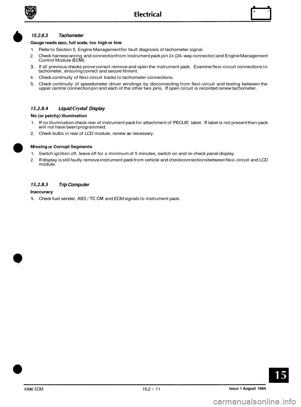
6 15.2.8.3 Tachometer
Gauge reads zero, full scale, too high or low
1.
2.
3.
4.
5. Refer
to Section 5, Engine Management for fault diagnosis of tachometer signal.
Check harness wiring and connection from Instrument pack pin
24 (24-way connector) and Engine Management
Control Module (ECM).
If all previous checks prove correct remove and open the instrument pack. Examine flexi-circuit connections to
tachometer, ensuring correct and secure fitment.
Check continuity of flexi
-circuit tracks to tachometer connections.
Check continuity of speedometer driver windings by disconnecting from flexi
-circuit and testing between the
upper central connection pin and each of the other two pins, If open circuit is recorded renew tachometer.
15.2.8.4 Liquid Crystal Display
No (or patchy) illumination
1.
2. If no illumination check rear of instrument pack for attachment of 'PECUS' label. If label is not present then pack
will not have been programmed.
Check bulbs in rear of LCD module, renew as necessary.
Missing or Corrupt Segments
1. Switch ignition off, leave off for a minimum of 5 minutes, switch on and re-check panel display.
2. If display is still faulty remove instrument pack from vehicle and checkconnections between flexi-circuit and LCD
module.
15.2.8.5 Trip Computer
Inaccuracy
1. Check fuel sender, ABS /TC CM and ECM signals to instrument pack.
Issue 1 August 1994 X300 EDM 15.2 - 11
Page 174 of 327
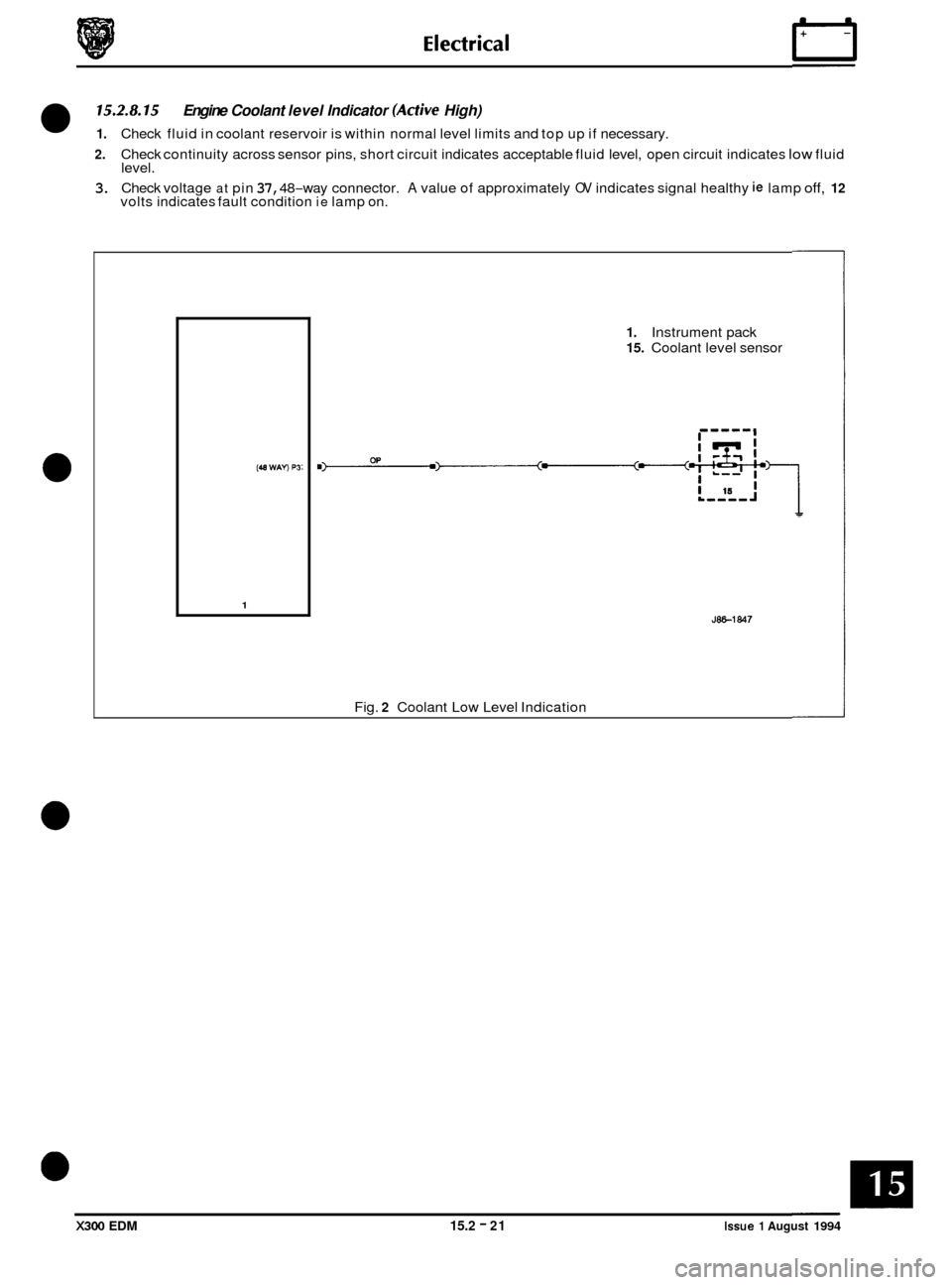
15.2.8.15
2. Check continuity across sensor pins, short circuit indicates acceptable fluid level, open circuit indicates low fluid
level.
3. Check voltage at pin 37, 48-way connector. A value of approximately OV indicates signal healthy ie lamp off, 12 volts indicates fault condition ie lamp on.
Engine Coolant level Indicator (Active High)
1. Check fluid in coolant reservoir is within normal level limits and top up if necessary.
(48 WAV P3i
1
1. Instrument pack
15. Coolant level sensor
JW-1847
Fig. 2 Coolant Low Level Indication
X300 EDM 15.2 - 21 Issue 1 August 1994