battery JAGUAR XJ6 1994 2.G Electrical Diagnostic Manual
[x] Cancel search | Manufacturer: JAGUAR, Model Year: 1994, Model line: XJ6, Model: JAGUAR XJ6 1994 2.GPages: 327, PDF Size: 13.73 MB
Page 11 of 327
IW Automatic Transmission (AJ16)
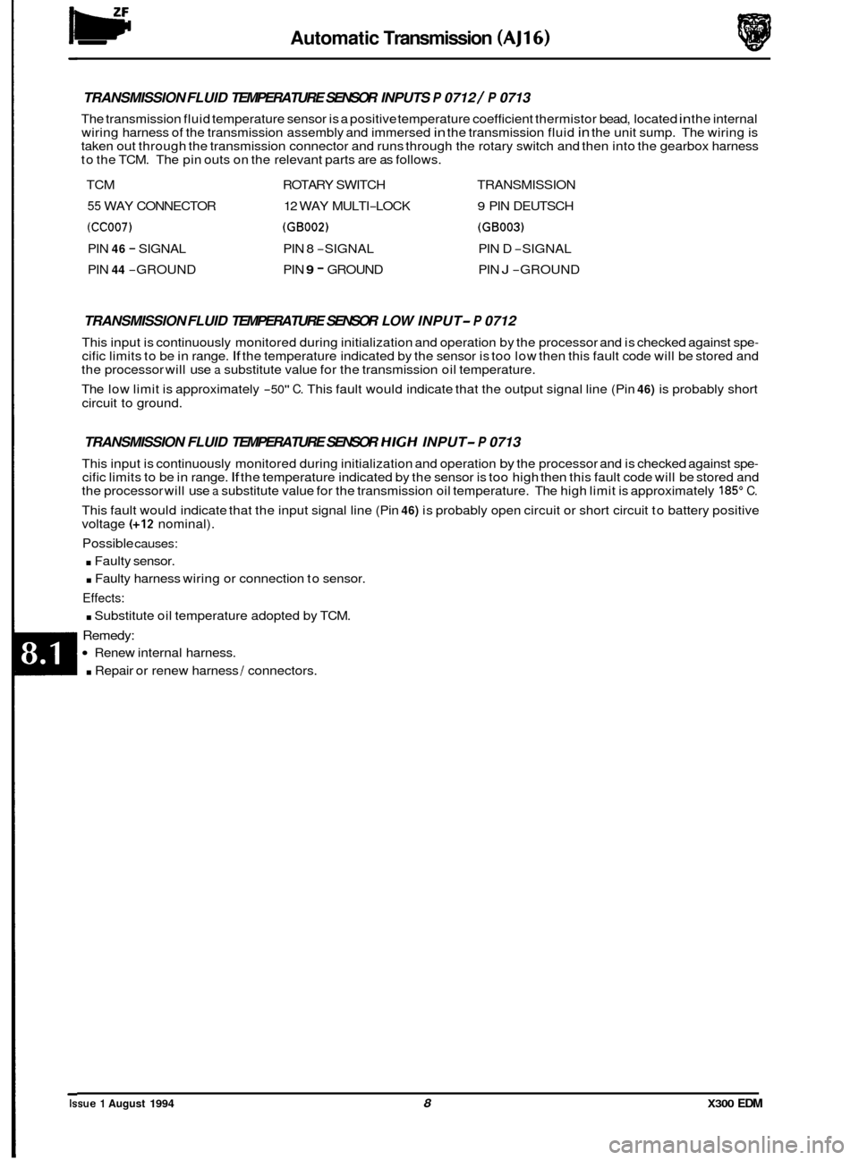
TRANSMISSION FLUID TEMPERATURE SENSOR INPUTS P 0712 / P 0713
The transmission fluid temperature sensor is a positive temperature coefficient thermistor bead, located in the internal
wiring harness of the transmission assembly and immersed in the transmission fluid in the unit sump. The wiring is
taken out through the transmission connector and runs through the rotary switch and then into the gearbox harness
to the TCM. The pin outs on the relevant parts are as follows.
TCM ROTARY SWITCH TRANSMISSION
55 WAY CONNECTOR 12 WAY MULTI-LOCK 9 PIN DEUTSCH
(CC007) (GB002) (GB003)
PIN 46 - SIGNAL PIN 8 -SIGNAL PIN D -SIGNAL
PIN
44 -GROUND PIN 9 - GROUND PIN J -GROUND
TRANSMISSION FLUID TEMPERATURE SENSOR LOW INPUT- P 0712
This input is continuously monitored during initialization and operation by the processor and is checked against spe- cific limits to be in range. If the temperature indicated by the sensor is too low then this fault code will be stored and
the processor will use a substitute value for the transmission oil temperature.
The low limit is approximately
-50" C. This fault would indicate that the output signal line (Pin 46) is probably short
circuit to ground.
TRANSMISSION FLUID TEMPERATURE SENSOR HIGH INPUT- P 0713
This input is continuously monitored during initialization and operation by the processor and is checked against spe- cific limits to be in range. If the temperature indicated by the sensor is too high then this fault code will be stored and
the processor will use a substitute value for the transmission oil temperature. The high limit is approximately 185" C.
This fault would indicate that the input signal line (Pin 46) is probably open circuit or short circuit to battery positive
voltage (+I2 nominal).
Possible causes:
. Faulty sensor.
. Faulty harness wiring or connection to sensor.
Effects:
. Substitute oil temperature adopted by TCM.
Remedy:
Renew internal harness.
. Repair or renew harness I connectors.
Issue 1 August 1994 8 X300 EDM
Page 13 of 327
Automatic Transmission (AJ16)
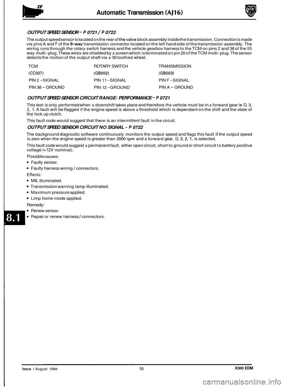
OUTPUT SPEED SENSOR - P 0721 / P 0722
The output speed sensor is located on the rear of thevalve block assembly inside the transmission. Connection is made
via pins A and F of the %way transmission connector located on the left hand side of the transmission assembly. The
wiring runs through the rotary switch harness and the vehicle gearbox harness to the TCM on pins 2 and 38 of the 55 way multi-plug. These wires are shielded by a screen which is terminated on pin 20 of the TCM multi-plug. The sensor
detects the motion of the output shaft via a 36 toothed wheel.
TCM ROTARY SWITCH TRANSMISSION
(CC007) (GB002) (GB003)
PIN 2 -SIGNAL PIN 11 -SIGNAL PIN F -SIGNAL
PIN 38
- GROUND PIN 12 -GROUND PIN
A - GROUND
OUTPUT SPEED SENSOR CIRCUIT RANGE/ PERFORMANCE - P 0721
This test is only performed when a downshift takes place and therefore the vehicle must be in a forward gear ie D, 3, 2, 1. A fault will be flagged if the engine speed is above a threshold which is dependant on the shift and the state of the lock up clutch.
This fault code would suggest that there is an intermittent fault in the circuit.
OUTPUT SPEED SENSOR CIRCUIT NO SIGNAL - P 0722
The background diagnostic software continuously monitors the output speed and flags this fault if the output speed
is zero when the engine speed is greater than 2000 rpm and a forward gear, D, 3,2,1, is selected.
This fault code would suggest
a permanent fault, either open circuit, short to ground or short circuit to battery positive
voltage (+12V nominal).
Possible causes:
Faulty sensor.
Faulty harness wiring I connectors.
Effects:
MIL illuminated.
Transmission warning lamp illuminated.
Maximum pressure applied.
Limp home mode applied.
Remedy:
Renew sensor.
Repair or renew harness I connectors. ~~~~ ~~
Issue 1 August 1994 10 X300 EDM
Page 17 of 327
w Automatic Transmission (AJ16)
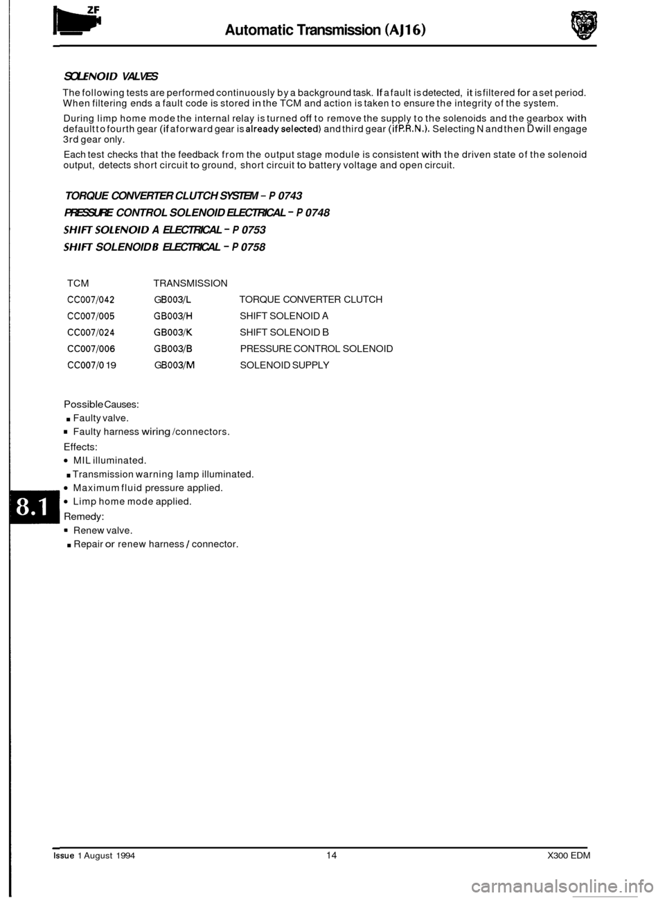
SOL ENOlD VALVES
The following tests are performed continuously by a background task. If a fault is detected, it is filtered for a set period.
When filtering ends a fault code is stored in the TCM and action is taken to ensure the integrity of the system.
During limp home mode the internal relay is turned
off to remove the supply to the solenoids and the gearbox with default to fourth gear (if aforward gear is alreadyselected) and third gear (if P.R.N.). Selecting N and then D will engage
3rd gear only.
Each test checks that the feedback from the output stage module is consistent
with the driven state of the solenoid
output, detects short circuit to ground, short circuit to battery voltage and open circuit.
TORQUE CONVERTER CLUTCH SYSTEM - P 0743
PRESSURE CONTROL SOLENOID ELECTRICAL
- P 0748
SHIFTSOLENOID A ELECTRICAL - P 0753
SHIH SOLENOID B ELECTRICAL - P 0758
TCM TRANSMISSION
ccoo7/042 G B003/L
CC007l005 GBOOYH
ccoo7/024 GB003lK
CC007/006 GB003/B
CC007/0 19 G B003/M
TORQUE CONVERTER CLUTCH
SHIFT SOLENOID
A
SHIFT SOLENOID B
PRESSURE CONTROL SOLENOID
SOLENOID SUPPLY
Possible Causes:
. Faulty valve.
Faulty harness wiring /connectors.
Effects:
MIL illuminated.
. Transmission warning lamp illuminated.
Maximum fluid pressure applied.
Limp home mode applied.
Remedy:
Renew valve.
. Repair or renew harness I connector.
Issue 1 August 1994 14 X300 EDM
Page 21 of 327
lw Automatic Transmission (AJ16)
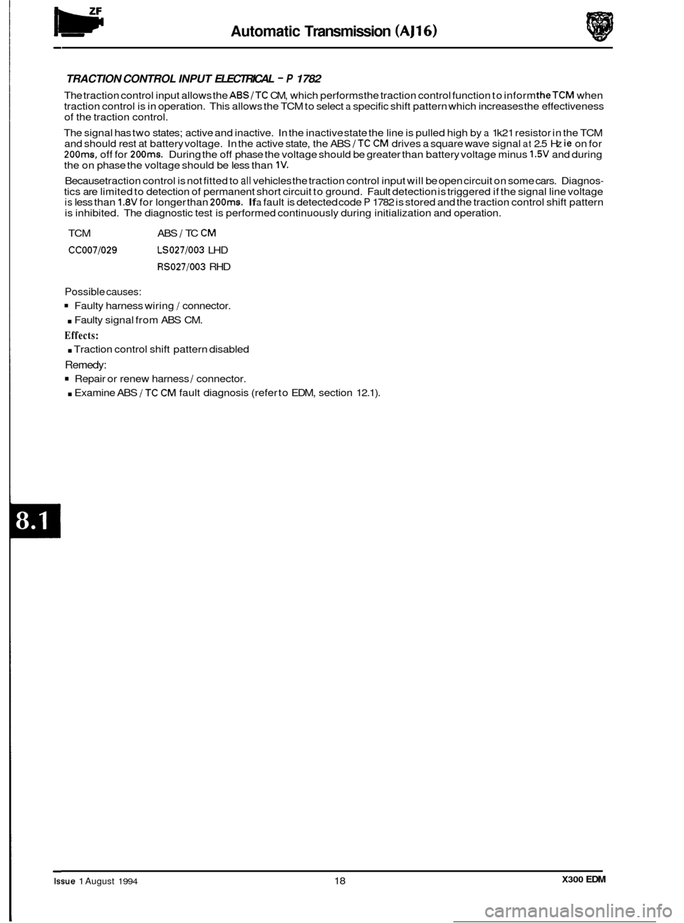
TRACTION CONTROL INPUT ELECTRICAL - P 1782
The traction control input allows the ABS/TC CM, which performs the traction control function to inform theTCM when
traction control is in operation. This allows the TCM to select a specific shift pattern which increases the effectiveness
of the traction control.
The signal has two states; active and inactive. In the inactive state the line is pulled high by
a 1 k21 resistor in the TCM
and should rest at battery voltage. In the active state, the ABS /TC CM drives a square wave signal at 2.5 Hz ie on for 200ms, off for 200ms. During the off phase the voltage should be greater than battery voltage minus 1.5V and during
the on phase the voltage should be less than 1V.
Because traction control is not fitted to all vehicles the traction control input will be open circuit on some cars. Diagnos- tics are limited to detection of permanent short circuit to ground. Fault detection is triggered if the signal line voltage is less than 1.8V for longer than 200ms. If a fault is detected code P 1782 is stored and the traction control shift pattern
is inhibited. The diagnostic test is performed continuously during initialization and operation.
TCM ABS
/ TC CM
CC007/029 LS027/003 LHD
RS027/003 RHD
Possible causes:
Faulty harness wiring / connector.
. Faulty signal from ABS CM.
Effects:
. Traction control shift pattern disabled
Remedy:
Repair or renew harness / connector.
. Examine ABS /TC CM fault diagnosis (refer to EDM, section 12.1).
0
0
0
0
X300 EDM Issue 1 August 1994 18
Page 23 of 327
w Automatic Transmission (AJ16)
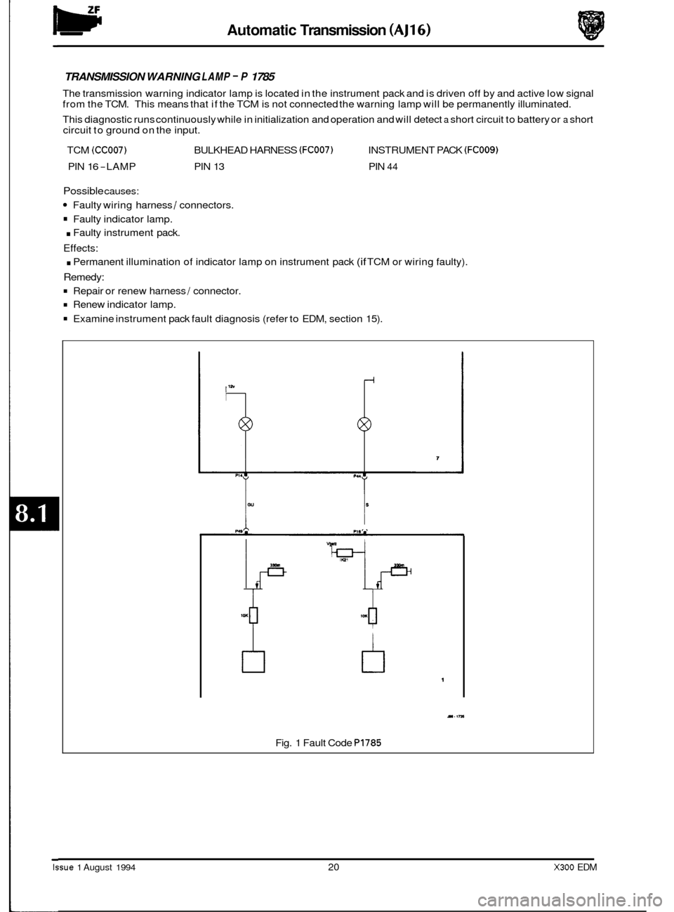
TRANSMISSION WARNING LAMP - P 1785
The transmission warning indicator lamp is located in the instrument pack and is driven off by and active low signal
from the TCM. This means that if the TCM is not connected the warning lamp will be permanently illuminated.
This diagnostic runs continuously while in initialization and operation and will detect
a short circuit to battery or a short
circuit to ground on the input.
TCM
(CC007) BULKHEAD HARNESS (FC007) INSTRUMENT PACK (FCOOS)
PIN 16 -LAMP PIN 13 PIN 44
Possible causes:
Faulty wiring harness / connectors.
Faulty indicator lamp.
. Faulty instrument pack.
Effects:
. Permanent illumination of indicator lamp on instrument pack (if TCM or wiring faulty).
Remedy:
Repair or renew harness / connector.
Renew indicator lamp.
Examine instrument pack fault diagnosis (refer to EDM, section 15).
/I
b
M(t I
4r^
tl 1
11.1rn
Fig. 1 Fault Code P1785
Issue 1 August 1994 20 X300 EDM
Page 26 of 327
Automatic Transmission (AJ16)
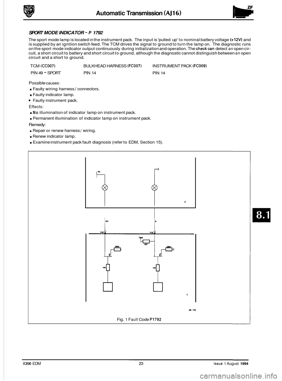
SPORT MODE INDICATOR - P 1792
The sport mode lamp is located in the instrument pack. The input is 'pulled up' to nominal battery voltage (+12V) and
is supplied by an ignition switch feed. The TCM drives the signal to ground to turn the lamp on. The diagnostic runs
on the sport mode indicator output continuously during initialization and operation. The
checkcan detect an open cir- cuit, a short circuit to battery and short circuit to ground, although the diagnostic cannot distinguish between an open
circuit and a short to ground.
TCM
(CC007) BULKHEAD HARNESS (FC007) INSTRUMENT PACK (FCOO9)
PIN 49 - SPORT PIN 14
PIN 14
Possible causes:
. Faulty wiring harness I connectors.
. Faulty indicator lamp.
Faulty instrument pack.
Effects:
. No illumination of indicator lamp on instrument pack.
. Permanent illumination of indicator lamp on instrument pack.
Remedy:
. Repair or renew harness 1 wiring.
. Renew indicator lamp.
0 . Examine instrument pack fault diagnosis (refer to EDM, Section 15).
1
Y.IM
Fig. 1 Fault Code PI792 ~~
X300 EDM 23 Issue 1 August 1994
Page 56 of 327
Automatic Transmission (V12) - Powertrain
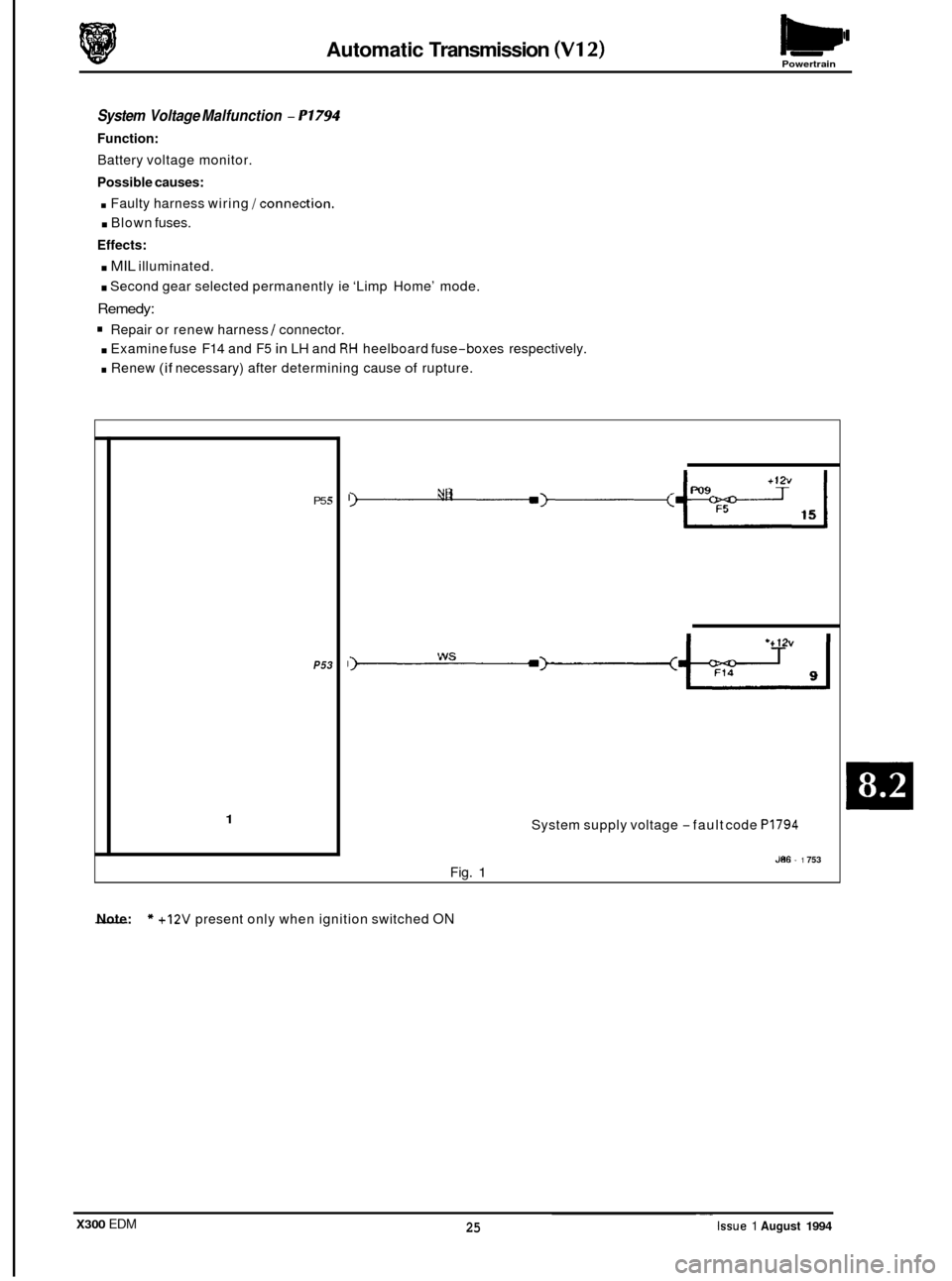
System Voltage Malfunction - P1794
Function:
Battery voltage monitor.
Possible causes:
. Faulty harness wiring /connection.
. Blown fuses.
Effects:
. MIL illuminated.
. Second gear selected permanently ie ‘Limp Home’ mode.
Remedy:
Repair or renew harness I connector.
. Examine fuse F14 and F5 in LH and RH heelboard fuse-boxes respectively.
. Renew (if necessary) after determining cause of rupture.
P5 5
P53
1
I -3---+-2 YR
System supply voltage -fault code PI794
J86 - 1 753 Fig. 1
- Note: * +12V present only when ignition switched ON
X300 EDM ~.
25 Issue 1 August 1994
Page 67 of 327
Brakes (a)
The input frequency of each sensor signal is translated, by the ABS /TC CM, into a comparable wheel speed. Should
any sensed speed be in excess of 330 km / h the relevant sensor is designated 'faulty' and ABS /TC control disabled.
Similarly ABS/TCcontrol is inhibited (switched off until fault condition is cleared) at speeds up to 40 km/ h whenfre- quency fluctuations are detected that are inconsistent with wheel rotation. At speeds above 40 km / h both systems
are disabled when inconsistencies are detected.
Traction control (where fitted) is achieved by using
a small motor and pulley arrangement to adjust the position of the
throttle flap. Under normal operating conditions the system is enabled by default. Operation of the Traction OFF / ON switch, located on the RH side of the fascia switch pack, disables the system and illuminates the TRACTION OFF lamp
located in the instrument pack.
Control is effected to prevent wheel spin by regulating (reducing) the throttle flap position, irrespective of the acceler
-
ator pedal position, using sensor signal comparisons and applying braking force to the wheel affected. Precise posi- tioning of the flap is achieved by monitoring the position of a throttle position sensor. When traction control is
requested
a gearshift inhibit signal is transmitted to the traction control module and cruise control (if selected) is dis- abled.
1
2
3
4
Battery positive feed (via fuse F7,located in the left-hand 'A' post lower fuse-box).
Battery positive feed (via fuse
F7,located in the right-hand 'A' post lower fusebox).
Gearshift inhibit
- during traction control.
Cruise control inhibit
- during traction control.
5/6 Wheel sensor
- LHF
7/8 Wheel sensor
- RHF
9/10 Wheel sensor
- LHR
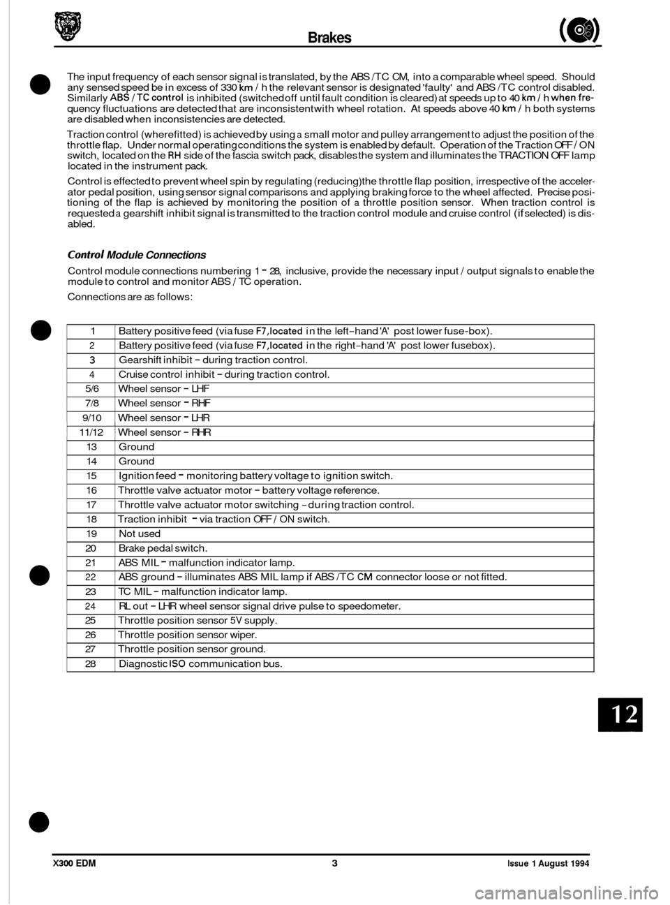
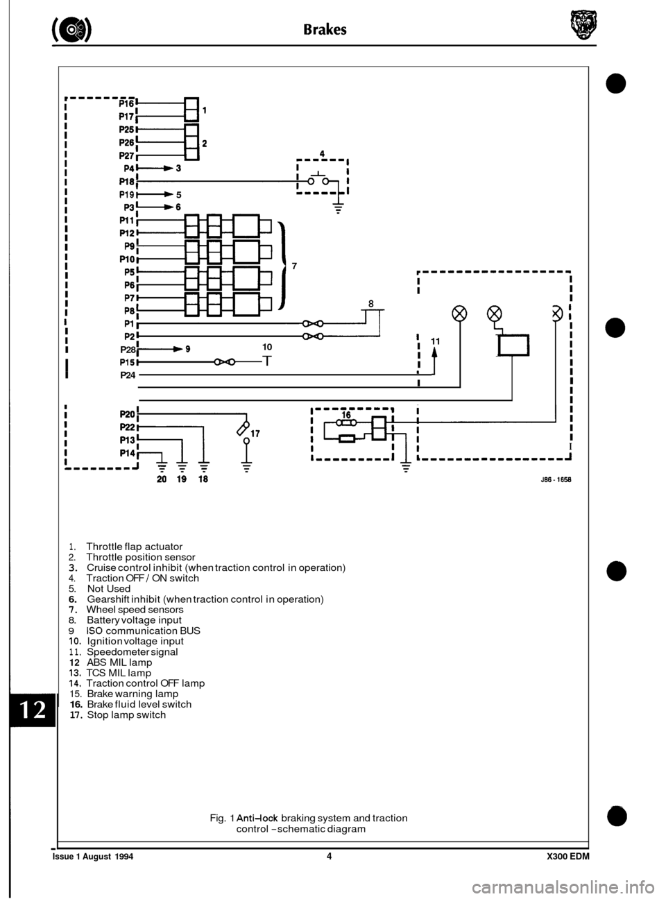
Control Module Connections
Control module connections numbering 1 - 28, inclusive, provide the necessary input / output signals to enable the
module to control and monitor ABS / TC operation.
Connections are as follows:
13 Ground
14 Ground
15
16
17
18
19 Not used
20 Brake pedal switch.
21
22
23
24
25
26 Throttle position sensor wiper.
27 Throttle position sensor ground.
28 Diagnostic
IS0 communication bus.
Ignition
feed
- monitoring battery voltage to ignition switch.
Throttle valve actuator motor
- battery voltage reference.
Throttle valve actuator motor switching
-during traction control.
Traction inhibit
- via traction OFF / ON switch.
ABS MIL
- malfunction indicator lamp.
ABS ground
- illuminates ABS MIL lamp if ABS /TC CM connector loose or not fitted.
TC MIL
- malfunction indicator lamp.
RL out
- LHR wheel sensor signal drive pulse to speedometer.
Throttle position sensor
5V supply.
I 1 11/12 1 Wheel sensor - RHR 1
X300 EDM 3 Issue 1 August 1994
Page 68 of 327
I I I I I I I I
I
I
I 11 I I
I
I
I I P24 1
I
I
I
I
I I I I I I I I
I
I
I
P19: 5
P3-6
7
8
I I I I P28 I-+ 9 10
I P15t T
I
I I I
I
,t I
I
I I I I I I I I
I
I I I
1. Throttle flap actuator 2. Throttle position sensor 3. Cruise control inhibit (when traction control in operation) 4. Traction OFF / ON switch 5. Not Used 6. Gearshift inhibit (when traction control in operation) 7. Wheel speed sensors 8. Battery voltage input
9 IS0 communication BUS IO. Ignition voltage input
1 1. Speedometer signal 12 ABS MIL lamp 13. TCS MIL lamp 14. Traction control OFF lamp 15. Brake warning lamp 16. Brake fluid level switch 17. Stop lamp switch
Fig.
1 Anti-lock braking system and traction
control
-schematic diagram
0
0
Issue 1 August 1994 4 X300 EDM
Page 70 of 327
Brakes
12.4 SYSTEM FAULT INDICATION
Fault Indication:
ABS MIL lamp is still illuminated after ignition switch on and instrument pack self test.
h:
Possible causes
Fuses blown.
Faulty wheel speed sensor or harness.
Faulty wiring.
Faulty ABS
/ TC CM.
It is likely that theTC MIL lamp and Traction OFF lamp will also illuminate on vehicles with traction control fitted.
Fault Diagnosis
On the first ignition cycle after afault has been sucessfully diagnosed and corrected the vehicle must bedriven to a speed above 20kph (12.5 mile/ h) before warning lamps will extinguish. If lamps remain on after this exer- cise repeat fault diagnosis.
. Check fuses (F7) in battery feed lines and (F16) in ignition line. Battery fuses are located in the left and right hand
. Unbolt 28 way multi-plug connector from ABS / TC CM.
. Measure resistance across each wheel speed sensor.
No - Unplug sensor flying lead and re-measure sensor resistance.
N&:
heelboard fuse boxes. The ignition supply fuse is located in the left hand heelboard fuse box.
Is value measured 1 10052, f 50%?
Rear sensor connectors are located beneath the rear seat. Seat must be removed to gain access to connector.
Forward sensor connectors are located adjacent to the hood catch bracket.
Is value now within range?
Yes
- Examine harness between ABS I TC CM and sensor.
No - Renew sensor.
= Check continuity to ground from ABS 1 TC CM harness connections 13 and 14. If value is much greater than 0.152
renew harness.
. With the ignition switch ON, measure voltage between ABS /TC CM harness connection 14 and connections 1 and 2 respectively. If value is not approximately equivalent to battery voltage renew harness.
. With the ignition switch ON, measure voltage between ABSITC CM harness connections14 and 15. If value is not
approximately equivalent to battery voltage renew harness.
Renew ABS /TC CM if fault is not located during the above procedures.
fault Indication:
ABS MIL lamp illuminates at 20 kph.
m:
Possible Causes
Fuses blown.
Faulty hydraulic module pump
/ motor unit or circuitry.
Faulty ABS
/ TC CM.
Fault Diagnosis
Check fuses.
. Disconnect pump / motor unit and measure resistance across two pin connector. Measured value should be in the
. Unbolt 28-way connector from ABS /TC CM and measure voltage between harness connections1 and 14. If value
. Renew ABS 1 TC CM if fault is not located during the above procedures.
It is IikelythattheTCMILlampandTraction OFFlampwill also illuminateonvehicleswithtractioncontrolfitted.
region of 0.852. Renew unit if excessive resistance or short circuit is recorded.
is not approximately equal to battery volts renew harness.
Issue 1 August 1994 X300 EDM