ECO mode JAGUAR XJ6 1994 2.G User Guide
[x] Cancel search | Manufacturer: JAGUAR, Model Year: 1994, Model line: XJ6, Model: JAGUAR XJ6 1994 2.GPages: 521, PDF Size: 17.35 MB
Page 330 of 521

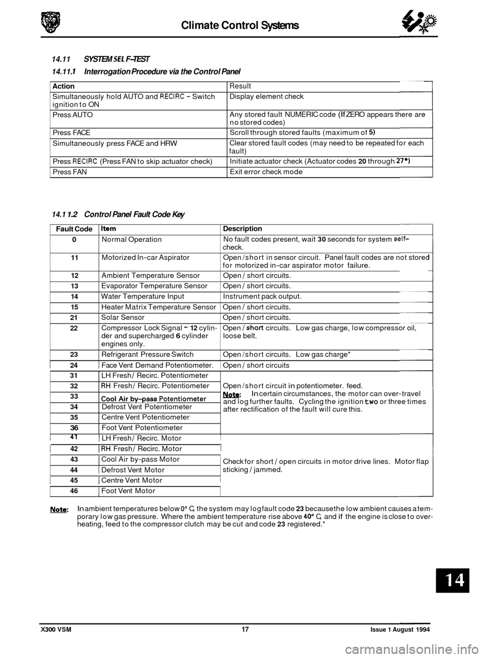
Climate Control Systems
Action
Simultaneously hold AUTO and RECIRC - Switch
ignition to ON
Press AUTO
Press FACE
Simultaneously press FACE and HRW
Press
RECIRC (Press FAN to skip actuator check)
Press FAN
14.11 SYSTEM SE1 F-TEST
14.11. I Interrogation Procedure via the Control Panel
Result
Display element check
Any stored fault NUMERIC code
(If ZERO appears there are
no stored codes)
Scroll through stored faults (maximum of
5)
Clear stored fault codes (may need to be repeated for each
fault)
Initiate actuator check (Actuator codes
20 through 27*)
Exit error check mode
Fault Code
0
11
12
13
14
15
21
22
0
23
14.1 1.2 Control Panel Fault Code Key
Item Description
Normal Operation No
fault codes present, wait 30 seconds for system self-
check.
Motorized In
-car Aspirator Open /short in sensor circuit. Panel fault codes are not stored
for motorized in
-car aspirator motor failure.
Ambient Temperature Sensor Open
/ short circuits.
Evaporator Temperature Sensor Open
/ short circuits.
Water Temperature Input Instrument pack output.
Heater Matrix Temperature Sensor Open
/ short circuits.
Solar Sensor Open
/ short circuits.
Compressor Lock Signal
- 12 cylin- Open /short circuits. Low gas charge, low compressor oil,
der and supercharged
6 cylinder loose belt.
engines only.
Refrigerant Pressure Switch Open /short circuits. Low gas charge*
31
32
33
34
35
36 0
I 24 1 Face Vent Demand Potentiometer. 1 Open / short circuits
LH Fresh
/ Recirc. Potentiometer
RH Fresh / Recirc. Potentiometer
cool ~i~ by-pass potentiometer
Defrost Vent Potentiometer
Centre Vent Potentiometer
Foot Vent Potentiometer Open
/short circuit
in potentiometer. feed.
w: and log further faults. Cycling the ignition two or three times
after rectification of the fault will cure this.
In certain circumstances, the motor can over-travel
43
44
I Defrost Vent Motor
I Cool Air by-pass Motor
I 41 I LH Fresh / Recirc. Motor I
Check for short / open circuits in motor drive lines. Motor flap
sticking
/ jammed.
1 42 I RH Fresh / Recirc. Motor I
1 45 I Centre Vent Motor I
46 I Foot Vent Motor
w: In ambient temperatures below Oo C, the system may log fault code 23 because the low ambient causes a tem-
porary low gas pressure. Where the ambient temperature rise above 40" C, and if the engine is close to over- heating, feed to the compressor clutch may be cut and code 23 registered.*
X300 VSM 17 Issue 1 August 1994
Page 345 of 521

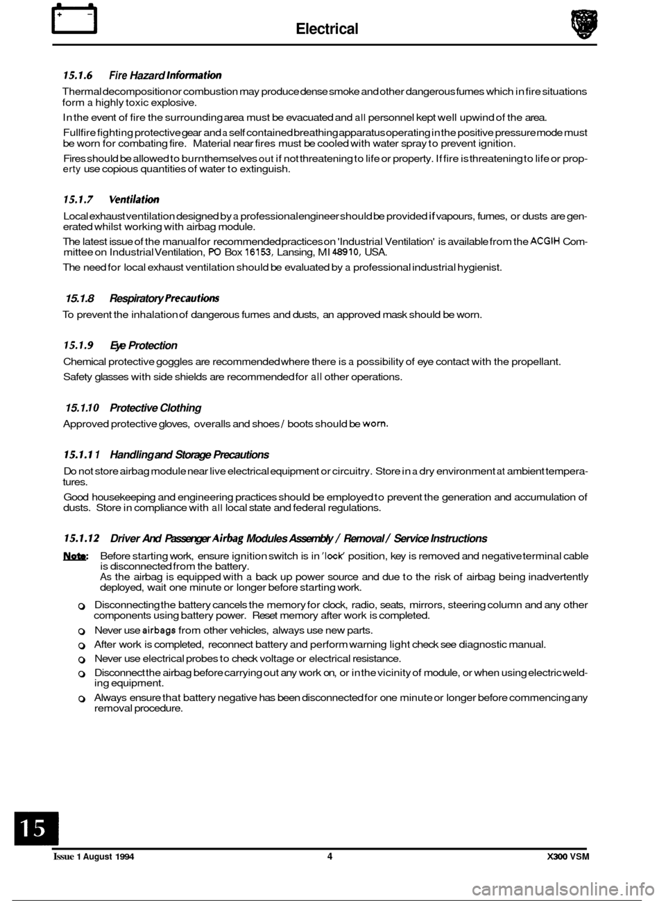
rl Electrical
15.1.6 Fire Hazard Infonnath
Thermal decomposition or combustion may produce dense smoke and other dangerous fumes which in fire situations
form
a highly toxic explosive.
In the event of fire the surrounding area must be evacuated and
all personnel kept well upwind of the area.
Full fire fighting protective gear and
a self contained breathing apparatus operating in the positive pressure mode must
be worn for combating fire. Material near fires must be cooled with water spray to prevent ignition.
Fires should be allowed to burn themselves
out if not threatening to life or property. If fire is threatening to life or prop- erty use copious quantities of water to extinguish.
15.1.7 Ventilath
Local exhaust ventilation designed by a professional engineer should be provided if vapours, fumes, or dusts are gen- erated whilst working with airbag module.
The latest issue of the manual for recommended practices on 'Industrial Ventilation' is available from the
ACGIH Com- mittee on Industrial Ventilation, PO Box 16153, Lansing, MI 48910, USA.
The need for local exhaust ventilation should be evaluated by a professional industrial hygienist.
15.1.8 Respiratory Precauth
To prevent the inhalation of dangerous fumes and dusts, an approved mask should be worn.
15.1.9 Eye Protection
Chemical protective goggles are recommended where there is a possibility of eye contact with the propellant.
Safety glasses with side shields are recommended for
all other operations.
15.1. I0 Protective Clothing
Approved protective gloves, overalls and shoes / boots should be worn.
15.1.1 1 Handling and Storage Precautions
Do not store airbag module near live electrical equipment or circuitry. Store in a dry environment at ambient tempera-
tures.
Good housekeeping and engineering practices should be employed to prevent the generation and accumulation of
dusts. Store in compliance with
all local state and federal regulations.
15.1.12 Driver And Passenger Airbag Modules Assembly / Removal / Service Instructions
Before starting work, ensure ignition switch is in 'IocK position, key is removed and negative terminal cable
is disconnected from the battery.
As the airbag is equipped with a back up power source and due to the risk of airbag being inadvertently
deployed, wait one minute or longer before starting work.
0 Disconnecting the battery cancels the memory for clock, radio, seats, mirrors, steering column and any other
components using battery power. Reset memory after work is completed.
0 Never use airbags from other vehicles, always use new parts.
0 After work is completed, reconnect battery and perform warning light check see diagnostic manual.
0 Never use electrical probes to check voltage or electrical resistance.
0 Disconnect the airbag before carrying out any work on, or in the vicinity of module, or when using electric weld- ing equipment.
0 Always ensure that battery negative has been disconnected for one minute or longer before commencing any
removal procedure.
EB
Issue 1 August 1994 4 X300 VSM
Page 384 of 521

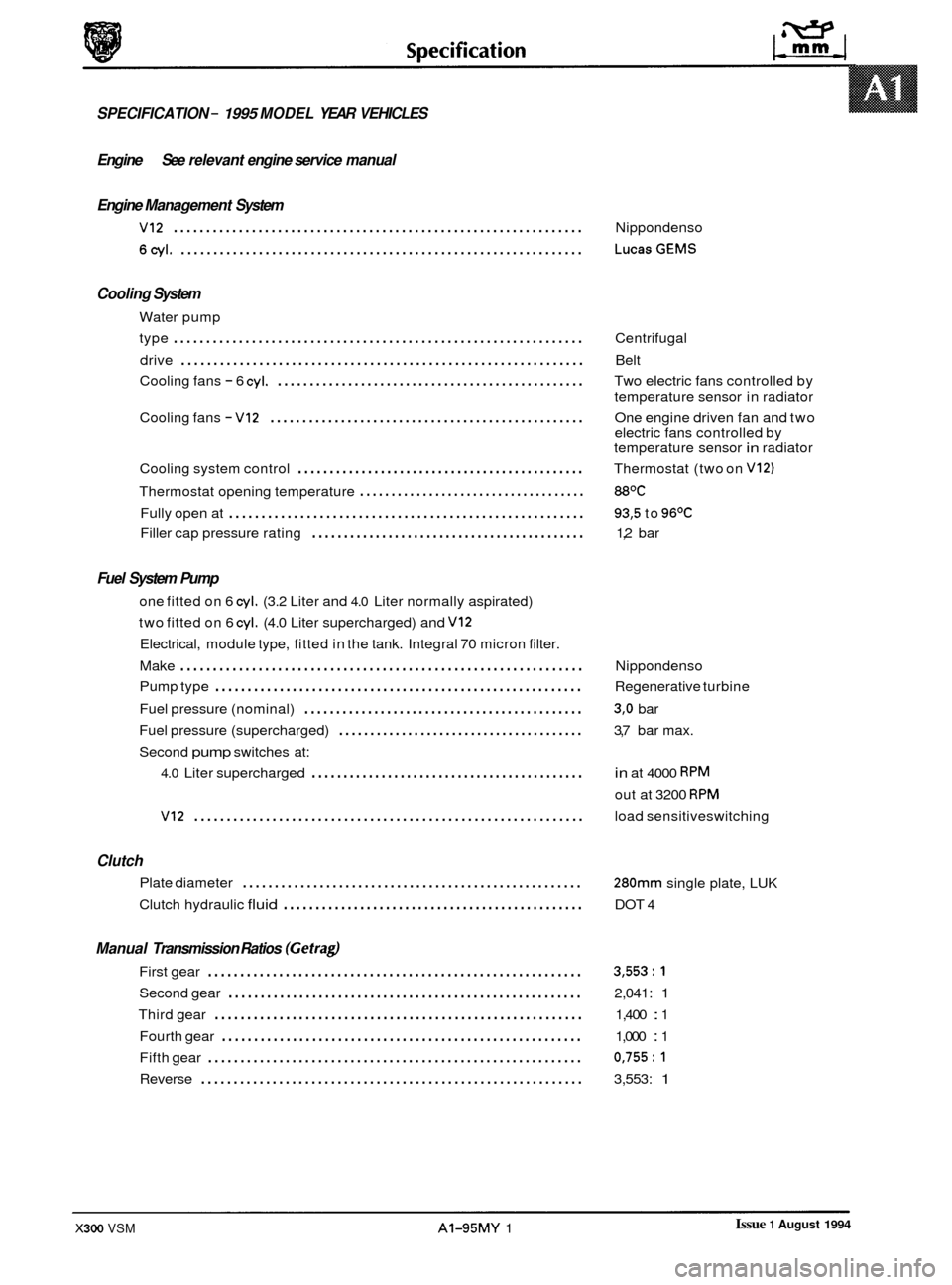
SPECIFICATION - 1995 MODEL YEAR VEHICLES
Engine See relevant engine service manual
Engine Management System
VI2 ............................................................... Nippondenso
6cyl. .............................................................. LucasGEMS
Cooling System
Water pump
type
............................................................... Centrifugal
Cooling fans
- 6 cyl. ................................................ Two electric fans controlled by
Cooling fans
- VI2 ................................................. One engine driven fan and two
Cooling system control
............................................. Thermostat (two on V12)
Thermostat opening temperature .................................... 88OC
Fully open at ....................................................... 93,5 to 96OC
Filler cap pressure rating ........................................... 1,2 bar
drive
.............................................................. Belt
temperature sensor in radiator
electric fans controlled by
temperature sensor
in radiator
Fuel System Pump
one fitted on 6 cyl. (3.2 Liter and 4.0 Liter normally aspirated)
two fitted on 6
cyl. (4.0 Liter supercharged) and VI2
Electrical, module type, fitted in the tank. Integral 70 micron filter.
Make
.............................................................. Nippondenso
Fuel pressure (nominal)
............................................ 3,O bar
Second
pump switches at:
Pump
type
......................................................... Regenerative turbine
Fuel pressure (supercharged)
....................................... 3,7 bar max.
4.0 Liter supercharged ........................................... in at 4000 RPM
out at 3200 RPM
VI2 ............................................................ load sensitiveswitching
Clutch
Plate diameter .....................................................
Clutch hydraulic fluid ............................................... DOT 4
280mm single plate, LUK
Manual Transmission Ratios (Gefragl
First gear .......................................................... 3,553:l
Second gear ....................................................... 2,041: 1
Third gear ......................................................... 1,400 : 1
Fourth gear
........................................................ 1,000 : 1
Fifth gear
.......................................................... 0,755:l
Reverse ........................................................... 3,553: 1
Issue 1 August 1994 X300 VSM AI-95MY 1
Page 452 of 521

A4.4.1 PAINT SYSTEMS - APPROVED
0 The manufacturer's paint systems listed below are currently approved for refinishing Jaguar vehicles.
I Manufacturer
Akzo Sikkens
1
Glasurit
0
1R-M
Bare metal etch primer Primer surfacer Base color coat
Washprimer Autocryll Autonova Autobase
, Centari 600*
System 56 (micatallic)
System 59 & 69 (pearl)
Wash
Etch+ System 54
(solidlmetallic)
Metal pre-treatment & Standox Basislak
rust remover 301.2595
I I
Galvaprep D840 Wash primer D831 Deltron HS 2
Eurof
il I
Hi-build primer
D855
Epoxy surfacer
DP40
Deltron
I non Iso-
cyanate Primer
D828
R-M Prof I Maxfill Diamont Basecoat
Clear lacquer
Autoclear 1000 - 3000
Automat
Centari
WO*
Clear lacquer 923-85
Standox Clearlak
Autocolor
Deltron Concept 2001
HS clear D880
Diamont Clearcoat
&&: * Not available North America
In markets which do not support any of the nominated systems, alternatives may
be used, provided that they comply
with the following company standards.
Product type Applicable standard
Bare metal etch primer
Base color and clear lacquer JMS
20.29.06
Primer surfacer JMS 20.29.11
JMS 20.29.09
CAUTION: To avoid damage to the vehicle interior, trim and plastic items, effective panel temperature must not ex- ceed 9S°C during paint cure process.
A4.4.1.1 General Recommendations
Recommendations and advice covering all aspects of refinishing may be found in the 'Paint Refinishing Manual'which
is available in the following languages:
Language Reference
Dutch AKM 9187
English AKM 9182
Italian AKM 9185
French AKM
9183
German AKM 9184
Spanish AKM 9186
0
A4.4.1.2 Manual Section Relevance
Section Relevance
Defect diagnosis Applicable
Refinish processes
Refinishing system
Color technique Applicable
Facilities and equipment Applicable
Safety Applicable
less 'De
-waxing' process
Applicable less model references (see table above)
Legislation applicable
U.K. only; general precautions and advice applicable to all
X300 VSM Issue 1 August 1994 25
Page 485 of 521

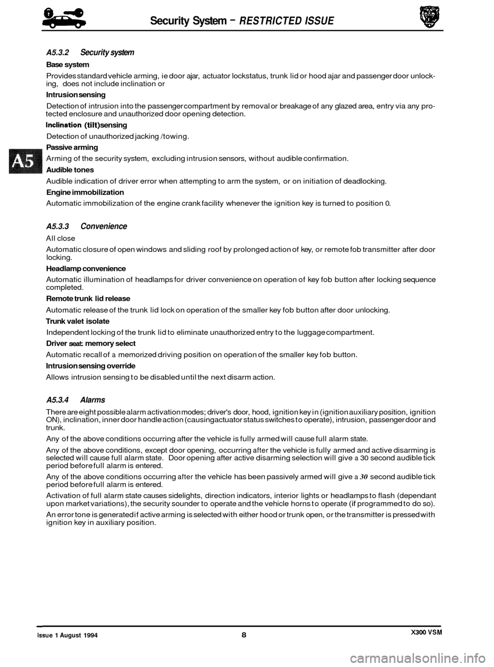
Security System - RESTRICTED ISSUE 8-8
-
A5.3.2 Security system
Base system
Provides standard vehicle arming, ie door ajar, actuator lockstatus, trunk lid or hood ajar and passenger door unlock- ing, does not include inclination or
Intrusion sensing
Detection of intrusion into the passenger compartment by removal or breakage of any glazed area, entry via any pro- tected enclosure and unauthorized door opening detection.
Inclination (tilt) sensing
Detection of unauthorized jacking /towing.
Passive arming
Arming of the security system, excluding intrusion sensors, without audible confirmation.
Audible tones
Audible indication of driver error when attempting to arm the system, or on initiation of deadlocking.
Engine immobilization
Automatic immobilization of the engine crank facility whenever the ignition key is turned to position 0.
A5.3.3 Convenience
All close
Automatic closure of open windows and sliding roof by prolonged action of key, or remote fob transmitter after door
locking.
Headlamp convenience
Automatic illumination of headlamps for driver convenience on operation of key fob button after locking sequence
completed.
Remote trunk lid release
Automatic release of the trunk lid lock on operation of the smaller key fob button after door unlocking.
Trunk valet isolate
Independent locking of the trunk lid to eliminate unauthorized entry to the luggage compartment.
Driver seat memory select
Automatic recall of a memorized driving position on operation of the smaller key fob button.
Intrusion sensing override
Allows intrusion sensing to be disabled until the next disarm action.
A5.3.4 Alarms
There are eight possible alarm activation modes; driver's door, hood, ignition key in (ignition auxiliary position, ignition ON), inclination, inner door handle action (causing actuator status switches to operate), intrusion, passenger door and
trunk.
Any of the above conditions occurring after the vehicle is fully armed will cause full alarm state.
Any of the above conditions, except door opening, occurring
after the vehicle is fully armed and active disarming is
selected will cause full alarm state. Door opening after active disarming selection will give a 30 second audible tick
period before full alarm is entered.
Any of the above conditions occurring
after the vehicle has been passively armed will give a 30 second audible tick
period before full alarm is entered.
Activation of full alarm state causes sidelights, direction indicators, interior lights or headlamps to flash (dependant
upon market variations), the security sounder to operate and the vehicle horns to operate
(if programmed to do so).
An error tone is generated if active arming is selected with either hood or trunk open, or the transmitter is pressed with
ignition key in auxiliary position.
0
X300 VSM Issue 1 August 1994 8
Page 493 of 521

Security System - RESTRICTED ISSUE
A5.6 SYSTEM DIAGNOSTIC METHODS
The following information details diagnostic proceduresfor system fault identification using a Portable Diagnostic Unit
(PDU).
PDU is designed and supplied by Jaguar Cars Ltd. to interrogate the electroniccontrol circuitry of the various vehicle
systems, diagnose fault conditions and indicate to the operator recorded faults and possible remedies. On initiation
of diagnostic procedures PDU will display the model variant and control module type,
a list of enabled functions can
also be accessed. Ensure that this information is correct for the vehicle under test, ie that the correct module is fitted
and
all appropriate options are enabled.
Detailed information on testing using PDU is detailed in the support documentation supplied with the unit.
Issue 1 August 1994 16 X300 VSM