ECO mode JAGUAR XJ6 1994 2.G Workshop Manual
[x] Cancel search | Manufacturer: JAGUAR, Model Year: 1994, Model line: XJ6, Model: JAGUAR XJ6 1994 2.GPages: 521, PDF Size: 17.35 MB
Page 2 of 521
Introduction
FOREWORD
This Vehicle Service Manual (VSM) is Dart
-
of a
set of service literature which covers -. diagnosis and rectification of problems associated with all areas of the X300 family of vehicles.
It is designed to be read in conjunction with other manuals, namely the various Unit Service Manuals (USM) (as
applicable to the particular vehicle under diagnosis/ repair) and the X300 Electrical Diagnostic Manual (EDM); see list
below.
It should be noted that its scope is limited to those areas that are unique to the family, e.g. Remove & Refit procedures
for Body Components, Engine, Transmission etcetera, Fuel, Emissions & Engine Management systems, and so on.
Fault Diagnosis and repair procedures (together
with Technical Data, Recommended Lubricants, Capacities etcetera) for major assemblies such as engines, automatic and manual transmissions, are covered in the separate Unit Service
Manuals.
The Unit Service Manuals are notvehicle
-specific, but are designed to be read in conjunction with this VSM, and, where so equipped, with other Jaguar Vehicle Service Manuals for new models launched subsequent to the X300 family.
The X300 Electrical Diagnostic Manual is the final part of the 'set' of service documentation. This manual
is
family-specific, and is designed to aid theTechnician to isolate electrical faults and to correct them. It covers all aspects
of electrical fault diagnosis, including:
OBD
II Codes and emission control system related fault diagnosis / rectification.
Circuit Diagrams
Component (Relays, fuse boxes, control modules etcetera) Location
/ Harness Diagrams I Ground Locations
Connector Locations.
Service Manuals Required
The Manuals required to service the X300 family of vehicles are as follows:
X300 Vehicle Service Manual
X300 Electrical Diagnostic Manual
Unit Service Manuals:
AJ16 Engine Service Manual
VI2 Engine Service Manual ZF AutomaticTransmissions Service Manual (ZF supplies transmissions for 3.2 liter and 4.0 liter normally aspirated
versions) Powertrain Automatic Transmissions Service Manual (The Powertrain name succeeds that of Hydra
-Matic.
Powertrain are suppliers of the 4L 80 E transmission as fitted to 4.0 litre supercharged and 6.0 litre versions)
Each
of the X3Okpecific manuals is divided into Sections which adopt the same title and number where relevant, i.e. Section 5.1 of both the VSM and the EDM cover Fuel, Emission Control & Engine Management System (AJ16). An
over
-all contents list showing each section title and number together with its page-edge locator is given in this section
and in the introduction to the EDM.
The VSM (not applicable to the EDM) also contains Appendices which cover specialized areas such as the current
vehicle specification, routine maintenance schedule etc. These are carried at the rear of this Manual, and have their
own contents page within this section.
INDEX
rapid location of information. The entries are set out as per the following example: @ This manual carries a comprehensive index at the rear, which is designed to save the Technician time by permitting
CLIMATE CONTROL SYSTEMS. Section 14.
See also Electrical Diagnostic Manual
Clutch
Description: Sect. 7.7 - 10
Fault diagnosis: Sect 7.1 - 11
In the example the heading in upper case lettering is to a section title, and it refers to the section number, 14, and also to the EDM as electrical diagnostic information will be found in that manual's section 14. The entry for clutch tells us that the relevant description will be found on page 10 of Section 7.1 of this manual, and
that fault diagnosis procedures start on page 11. In this case there is no reference to the EDM as electrical diagnosis does not apply to this area.
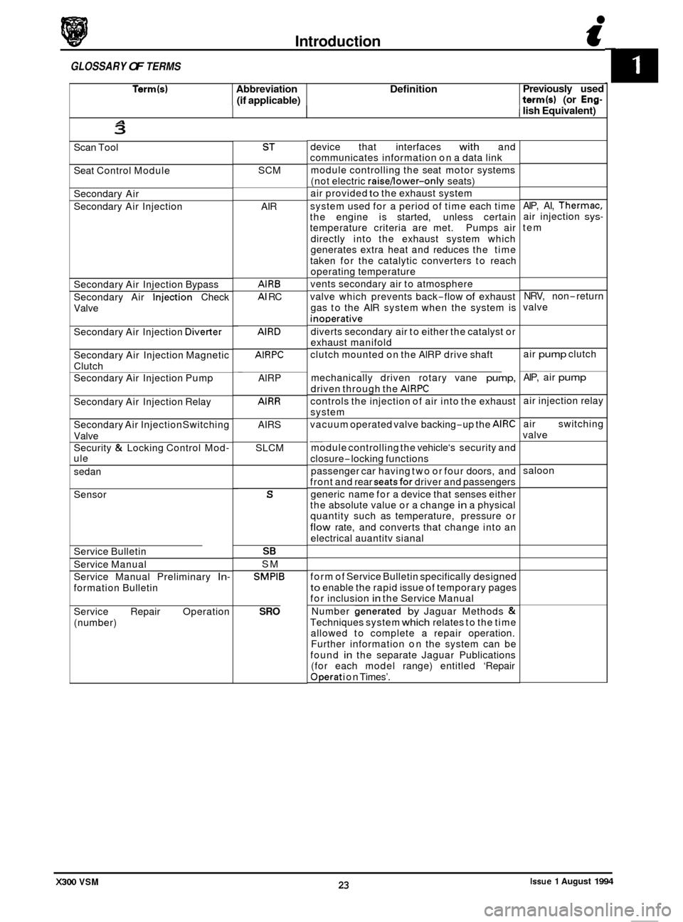
GLOSSARY OF TERMS
This Section contains a Glossary of general and emissions-related terminology (commencing on page 5).
X300 VSM 1 Issue 1 August 1994
Page 24 of 521
0
Term(s) Abbreviation Definition
(if applicable)
Introduction i
Previously used term(s) (or Eng-
GLOSSARY OF TERMS
I lish Equivalent) A 3
Scan Tool
Seat Control Module
Secondary Air
Secondary Air Injection
Secondary Air Injection Bypass
..
Secondary Air -Injection Check
Valve
Secondary Air Injection
Diverter
Secondary Air Injection Magnetic
Clutch
Secondary Air Injection Pump
Secondary Air Injection Relay
Secondary Air Injection Switching
Valve
Security
& Locking Control Mod- ule
sedan
Sensor
Service Bulletin
Service Manual
Service Manual Preliminary
In-
formation Bulletin
Service Repair Operation
(number)
ST
SCM
AIR
AlRB
AI RC
AlRD
AIRPC
AlRP
AlRR
AIRS
SLCM
-
S
SE
SM
SMPlB
SRO
device that interfaces with and
communicates information on a data link
module controlling the seat motor systems
(not electric
raisejower-only seats)
air provided
to the exhaust system
system used for a period of time each time
the engine is started, unless certain
temperature criteria are met. Pumps air
directly into the exhaust system which
generates extra heat and reduces the time
taken for the catalytic converters to reach
operating temperature
vents secondary air to atmosphere
valve which prevents back
-flow of exhaust
gas to the AIR system when the system is
inoDerative
diverts secondary air to either the catalyst or
exhaust manifold
clutch mounted on the AlRP drive shaft
mechanically driven rotary vane
pump,
driven through the AIRPC
controls the injection of air into the exhaust
system
vacuum operated valve backing
-up the AlRC
module controlling the vehicle‘s security and
closure
-locking functions
passenger car having two or four doors, and
front and rear
seatsfor driver and passengers
generic name for a device that senses either
the absolute value or a change
in a physical
quantity such as temperature, pressure or
flow rate, and converts that change into an
electrical auantitv sianal
__
form of Service Bulletin specifically designed
to enable the rapid issue of temporary pages
for inclusion in the Service Manual
Number
generated by Jaguar Methods &
Techniques system which relates to the time
allowed to complete a repair operation.
Further information on the system can be
found
in the separate Jaguar Publications
(for each model range) entitled ‘Repair
Operat ion Times’. AIP,
AI,
Thermac, air injection sys-
tem
NRV, non-return
valve
air
pump clutch
AIP, air
pump
air injection relay
air switching
valve
saloon
Issue 1 August 1994 23 X300 VSM
Page 49 of 521
3.2.2 ENGINE - GEARBOX/ TRANSMISSION
ASSEMBLY, RENEW
SRO 12.37.01/90
The engine /transmission unit on the V12 6.0 liter model is mounted on three engine mounting / bracket assemblies
fitted to the front crossmember on either side of the engine bay. The engine/ transmission rear mount is a mounting
bracket and spring assembly fitted and secured to body underframe longitudinal members. For access to remove the
engine carry
out the following procedures:
WARNING: WHEN WORKING WITHIN THE ENGINE COMPARTMENT, KEEP CLEAR OF THE RADIATOR COOLING
FANS AS THEY COULD START WITHOUT WARNING, EVEN IF THE ENGINE IS NOT RUNNING.
. Remove the hood, see SRO 76.16.01, section 13.
. Remove the two air cleaner assemblies, see SRO’s 19.10.01 & 19.10.02.
. Remove the engine cover, see SRO 12.29.93 (V12 Engine Service Manual).
Depressurize the fuel system, see SRO 19.50.02, section 5.1.
In line with the relevant SRO’s and sections, remove all appropriate obstructing parts, including their fixing and
. Disconnect all mechanical and isolate all electrical linkages leading to and from the engine.
. De-gas the air conditioning system, see section 14, Charge Recovery (System depressurization).
Disconnect
the battery.
mounting arrangements.
CAUTION: Do
not vent refrigerant directly to the atmosphere and always use Jaguar approved recovery/recycle/ra charge equipment.
Drain the engine oil, see 3.2.3 this section.
Drain the coolant, see SRO 26.10.01, section 4.1.
WARNING: DO NOT REMOVE THE HEADER TANK PRESSURE CAP WHILE THE ENGINE IS HOT. IF THE CAP MUST
BE REMOVED, PROTECT THE HANDS AGAINST ESCAPING STEAM AND SLOWLY TURN THE CAP ANTI- CLOCKWISE UNTIL THE EXCESS PRESSURE CAN ESCAPE. LEAVE THE CAP IN THIS POSITION UNTIL ALL
STEAM AND PRESSURE HAS ESCAPED AND THEN REMOVE THE CAP COMPLETELY.
Before
lifting the complete engine/transmission unit with an engine hoist from the engine bay, ensure that two engine
lifting brackets (tool 18G. 1465) are secured equallyspaced to the inlet manifold studs. The four engine lifting brackets
should be positioned towards the front and the rear of the assembly. Ensure the front of thevehicle is jacked
up secure- ly on stands when removing the assembly.
X300 VSM Issue 1 August 1994 2
Page 140 of 521
Automatic Transmission (AJ16)
Both types of automatic transmission comprise a hydrodynamic torque converter driving an epicyclic gear train which
provides four forward ratios and reverse. Gearshift selection is made by a hydraulic (or electronichydraulic) trans- mission control unit. Six gearshift positions are provided:
Position
'P' (Park) -the driven wheels are mechanically locked at the transmission.
Position
'R' (Reverse) - reverse gear selected.
Position
'N' (Neutral) - engine disconnected from drive-line and wheels.
Position 'D' (Drive)
- all four speed ranges are selected automatically with lock-up available in top gear only.
Position
'3' - automatic selection of the lowest three speed ranges only.
Position '2'
- automatic selection of the lowest two speed ranges only; the transmission is prevented from shift- ing up to the third and top speed ranges.
Immediate selection of a lower ratio is also available, within mapped limits, by 'kick
-down' (pressing the accelerator
pedal down beyond the normal full throttle position) for example when overtaking.
A brake pedal/gearshift interlock is incorporated in the shift lever mechanism. Theshift lever may only be movedfrom
the 'P' (Park) position if the ignition key switch is in position 'll', and the foot brake is applied. The ignition key cannot
be removed from the ignition switch unless the shift lever is in the 'P' (Park) position. Once the ignition key has been
removed, the shift lever is locked in the Park position. The gearshift interlock may be over-ridden manually in the event
of an electrical failure or when it is required to move the vehicle manually for access, ie for removal of the propeller
shaft.
8.1.1.1
Gearshift selection causes the appropriate gear to be selected through a cable operated shift lever on the side of the
Gear Selection (ZF 4HP 22)
transmission unit. When a gea; is selected, the shift points are determined by accelerator pedal position through a
throttle cable connection and by pressures equivalent to road speed derived from a centrifugal governor on the output
shaft.
Gearshift speed and quality are controlled by the hydraulic control unit located in the lower part of the transmission
housing. The control unit contains selector valve, control pistons and pressure valves.
The hydraulic control unit can be overridden by 'kickdown'. This is actuated by the final travel of the accelerator pedal
and causes the next lower gear to be selected.
8.1.1.2
Gearshift selection causes the appropriate gear to be selected through a cable operated shift lever on the side of the
transmission unit; the shift lever also operates a rotary switch attached to the side of the transmission unit. When a
gear is selected, the rotary switch provides an output or combination of outputs to the TCM, which continuously moni
- tors the gear selected in addition to output shaft speed and transmission oil temperature. Information from the Engine
Control Module (ECM) representing engine speed, load and throttle position is also fed to the TCM to enable the most
suitable gear to be selected.
Gear selection and gearshift speeds are controlled by the manually operated selector valve, a solenoid operated pres
- sure regulator and three solenoid valves. On receipt of signalsfrom the TCM, the three solenoid valves MVI, MV2 and
MV3, in various combinations with the safety valve, determine the appropriate gear range. The TCM, on receipt of
information of engine state and road speed, determines the shift speed.
The Performance Mode switch, located on the shift lever surround, provides two alternative shift speed patterns:
1. 'Normal (Economy) Mode' - designed for everyday use.
2. 'Sport Mode'
- gear shift takes place at higher road speeds to enhance performance.
The 'kick
-down' switch, located beneath the accelerator pedal, is actuated by the final travel of the pedal and signals
to the TCM that the next lower gear is to be selected.
Gear Selection (ZF 4 HP 24 E)
X300 VSM 3 Issue 1 August 1994
Page 147 of 521
Automatic Transmission (AJl6)
. Ensure the shift lever is in 'N'.
. Fit and fully seat a new rotary switch to the transmission
unit.
Fit but do not fully tighten the rotary switch securing nuts.
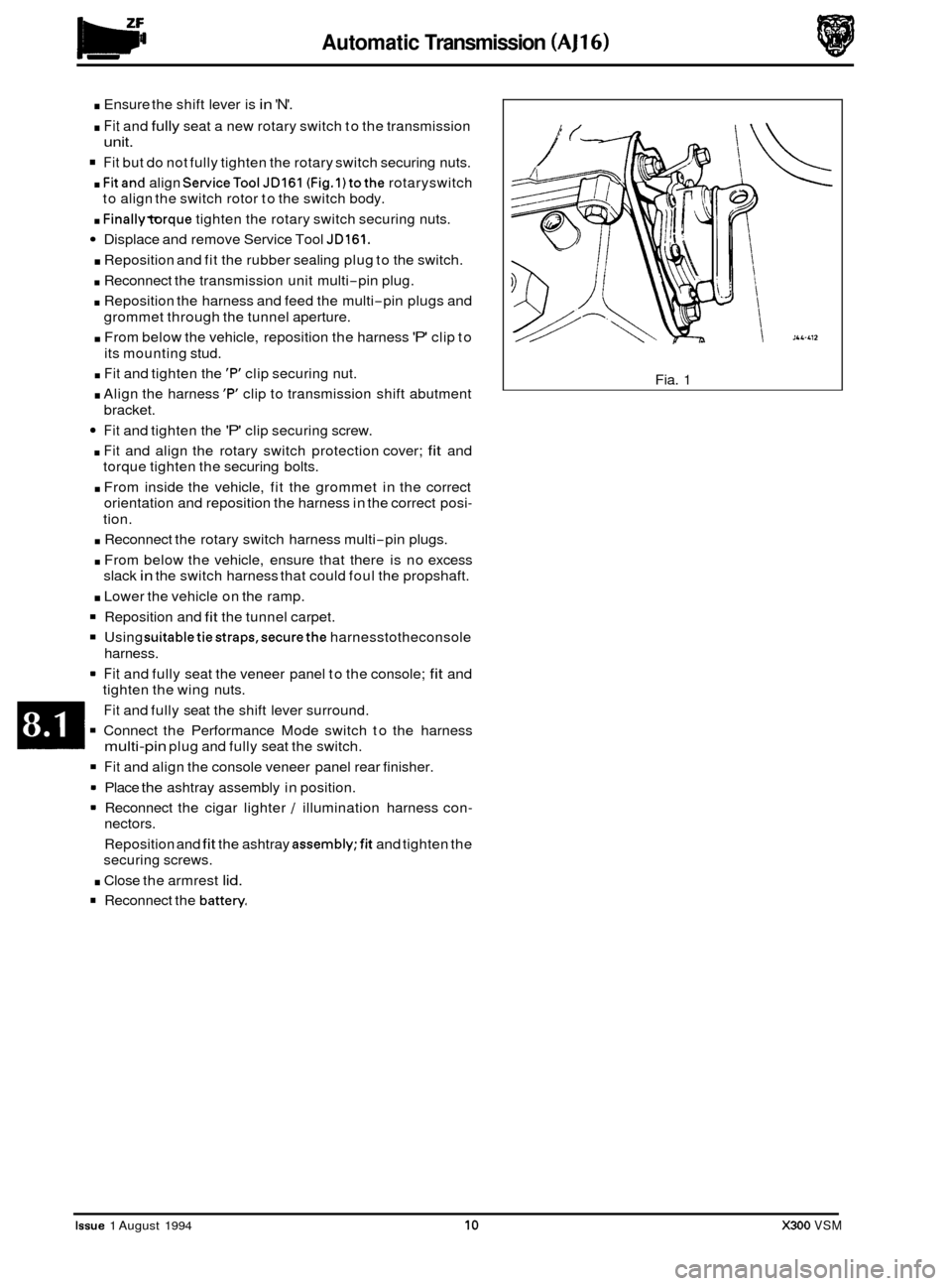
. Fitand align ServiceTool JD161 (Fig.l)tothe rotaryswitch
. Finallytorque tighten the rotary switch securing nuts.
Displace and remove Service Tool JD161.
. Reposition and fit the rubber sealing plug to the switch.
. Reconnect the transmission unit multi-pin plug.
. Reposition the harness and feed the multi-pin plugs and
. From below the vehicle, reposition the harness 'P' clip to
. Fit and tighten the 'F" clip securing nut.
. Align the harness 'P' clip to transmission shift abutment
Fit and tighten the 'P' clip securing screw.
. Fit and align the rotary switch protection cover; fit and
torque tighten the securing bolts.
. From inside the vehicle, fit the grommet in the correct
orientation and reposition the harness in the correct posi
-
tion.
to
align the switch rotor to the switch body.
grommet through the tunnel aperture.
its mounting stud.
bracket.
. Reconnect the rotary switch harness multi-pin plugs.
. From below the vehicle, ensure that there is no excess
slack
in the switch harness that could foul the propshaft.
. Lower the vehicle on the ramp.
Reposition and fit the tunnel carpet.
Using suitabletiestraps,securethe harnesstotheconsole
= Fit and fully seat the veneer panel to the console; fit and
harness.
tighten the wing nuts.
Fit and fully seat the shift lever surround.
multi-pin plug and fully seat the switch.
Connect the Performance Mode switch to the harness
Fit and align the console veneer panel rear finisher.
9 Place the ashtray assembly in position.
= Reconnect the cigar lighter / illumination harness con-
nectors.
Reposition and
fit the ashtray assemb1y;fit and tighten the
securing screws.
. Close the armrest lid.
Reconnect the battery
Fia. 1
Issue 1 August 1994 10 X300 VSM
Page 156 of 521
Automatic Transmission (V12 & AJl6 Supercharged) Pomrtrain
8.2.1 GENERAL DESCRIPTION
This section provides information relating to the Powertrain 4L80-E transmissions fitted to the 4,O liter supercharged
engine (4,OL SC) and to the 6,O liter engine (6,OL).
The Powertrain 4L80-E is a four-speed, high torque capacity, electronically controlled automatic transmission, which
comprises a torque converter with lock-up direct drive clutch and three planetary gear sets. Five multiple diskclutches,
one intermediate sprag clutch assembly, two roller clutch assemblies and two band assemblies provide the drive el- ements necessary for correct sequential gear engagement and operation.
The torque converter containing
a pump, a turbine (rotor), a stator assembly, and a clutch pressure disksplined to the
turbine, acts as a fluid coupling for smooth torque transmission from the engine. The converter also supplies addi- tional torque multiplication when necessary, and the torque converter clutch (TCC) pressure disk provides a mechan- ical direct drive or 'lock-up' above a certain speed in top gear for greater fuel economy.
Gearshift operations are controlled from the Transmission Control Module (TCM), which governs the electronically
controlled valve body situated within the transmission.
Three planetary gear sets provide reverse and the four forward ratios, the changing of which is fully automatic in rela
- tion to load, vehicle speed and throttle opening. The Transmission Control Module receives and integrates various ve- hicle sensor input signals, and transmits operating signals to the solenoids located in the control valve assembly.
These solenoids govern the transmission operating pressures, up-shift and down-shift gear selection patterns and
also the torque converter clutch operation by pulse width modulated control.
8.2.1.1 Gear Ranges
Selectable gear positions are: P - Park, R - Reverse, N - Neutral, D - Drive, 3, 2.
P - Park position of the shift lever provides a mechanical locking of the output shaft of the transmission, and as such,
must only be engaged when the the vehicle is stationary. In addition, and for
extra safety, the handbrake should also
be applied. It is necessary to have the ignition ON and the footbrake applied to move the shift lever from the Park
position. For ignition key removal the shift lever must be in the Park position. The engine can be started in the Park
position.
R - Reverse enables the vehicle to be operated in a rearwards direction. The engine cannot be started in the Reverse
position.
N
-Neutral position enables the engine to be started and operated without driving the vehicle. It also allows the vehicle
to be moved manually for access, ie for removal of the propeller shaft.
D
-Drive position allows the automatic selection of all four forward gear ratios during normal driving conditions for
maximum efficiency and fuel economy. On acceleration, down-shifts are obtained by depressing the accelerator pedal
or by manual selection. The engine cannot be started in this position.
3
- Manual third position allows automatic operation of the three lower gear ratios but inhibits selection of the fourth
ratio. This position is used for towing a trailer or negotiating hilly terrain when greater engine braking control is re- quired. The engine cannot be started in this position.
2 - Manual second position allows automatic operation of the two lower gear ratios but inhibits selection of the third
and fourth ratios. This position is used for heavy traffic congestion or negotiating hilly terrain when even greater en
- gine braking control is required than is provided by manual third. This ratio may be selected at any vehicle speed - even if the transmission is in third or fourth ratio, the transmission will immediately down-shift to second gear pro- vided the vehicle speed is below 137 km / h (85 mile / h). The engine cannot be started in this position.
N.g!b: With the Performance Mode switch in the NORMAL position, the vehicle will pull away in second gear. How- ever, if more than 75 per cent of throttle is applied when the vehicle speed is between zero and 13 km/ h (8 mile / h), then first gear will be selected. From 13 to 61 km/ h (8 to 38 mile/ h) first gear is obtainable by 'kick-down'.
In 'sport' mode thevehicle pulls away in first gear and the transmission operatesfully in all four forward gears.
X300 VSM 1 Issue 1 August 1994
Page 238 of 521
Brakes
The pressure at the inlet valves corresponds to the opening pressure of the relief valve (item 15) incorporated in the
isolation valve. Excess brake fluid is drained to the suction side of the pump via the relief valve and returns either to
the TMC secondary circuit and on to the
fluid reservoir, or is directly drawn on by the pump.
As soon as the spinning wheel has been braked down into the normal range of wheel spin, the NO valves (items
16 or 17) close to prevent any further increase in brake pressure. Depending upon the acceleration of the wheel, the NC
valve (item
20 or 21) may open to decrease thesecondary circuit brake pressure. NCvalves (item 17 or 18) may remain
closed in orderto achieve a brake pressure holding phase. If the pressure in the secondarycircuit needs to be increased
again, the NC valve closes again (if open) and the NO valve opens, diverting the necessary volume flow. This control
action, keeps the wheel in the range of optimum slip until the spinning tendency ceases.
The NO isolation valve
(14) remains closed throughout the traction control cycle.
An actuation of the brake, sensed by the control module, causes the traction control mode to be terminated and the
isolation valve (item
14) to be opened. The TMC pressure simultaneously closes the hydraulic inlet valve (item 13) so that the pump can no longer draw fluid from it. The ABS / TC CM now operates in normal ABS mode.
m: When traction control is initiated, speed control is deactivated (if in operation) and requires re-setting after
the traction control mode has terminated. Gear shift is inhibited on automatic transmission vehicles; no down- shifts are allowed and upshifts occur at 4800 RPM.
X300 VSM 15 Issue 1 August 1994
Page 317 of 521
Climate Control Systems
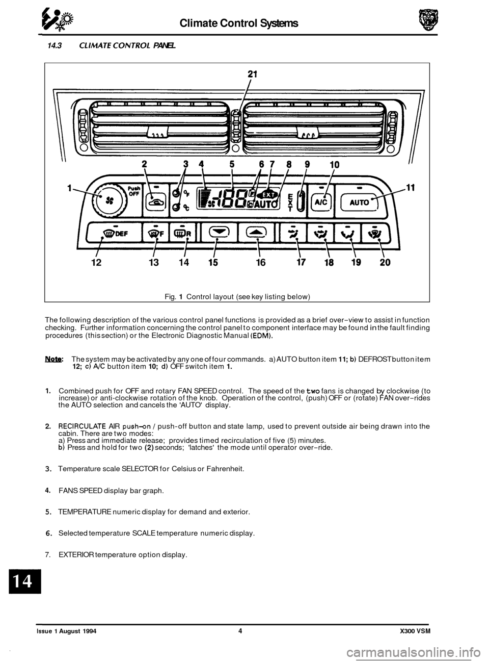
14.3 CLIMATECONTROL PANEL
12 13 14 15 16
Fig. 1 Control layout (see key listing below)
The following description of the various control panel functions is provided as a brief over
-view to assist in function
checking. Further information concerning the control panel to component interface may be found in the fault finding
procedures (this section) or the Electronic Diagnostic Manual (EDM).
Iynfe: The system may be activated by any one of four commands. a) AUTO button item 1 1; b) DEFROST button item 12; c) NC button item 10; d) OFF switch item 1.
1. Combined push for OFF and rotary FAN SPEED control. The speed of the two fans is changed by clockwise (to
increase) or anti-clockwise rotation of the knob. Operation of the control, (push) OFF or (rotate) FAN over-rides
the AUTO selection and cancels the 'AUTO' display.
2. RECIRCULATE AIR push-on / push-off button and state lamp, used to prevent outside air being drawn into the
cabin. There are two modes:
a) Press and immediate release; provides timed recirculation of five
(5) minutes. b) Press and hold for two (2) seconds; 'latches' the mode until operator over-ride.
3. Temperature scale SELECTOR for Celsius or Fahrenheit.
4. FANS SPEED display bar graph.
5. TEMPERATURE numeric display for demand and exterior.
6. Selected temperature SCALE temperature numeric display.
7. EXTERIOR temperature option display.
Issue 1 August 1994 4 X300 VSM
Page 318 of 521
Climate Control Systems
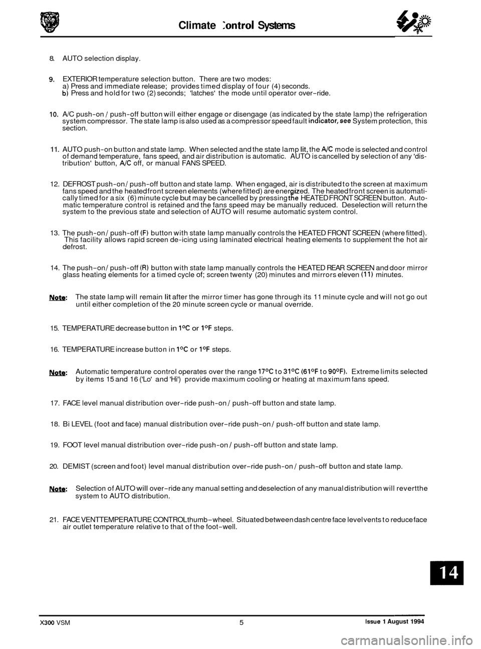
8. AUTO selection display.
9. EXTERIOR temperature selection button. There are two modes:
a) Press and immediate release; provides timed display of four (4) seconds.
b) Press and hold for two (2) seconds; 'latches' the mode until operator over-ride.
10. A/C push-on / push-off button will either engage or disengage (as indicated by the state lamp) the refrigeration
system compressor. The state lamp is also used as a compressor speed fault indicator,see System protection, this
section.
11. AUTO push-on button and state lamp. When selected and the state lamp lit, the A/C mode is selected and control
of demand temperature, fans speed, and air distribution is automatic. AUTO is cancelled by selection of any 'dis- tribution' button, A/C off, or manual FANS SPEED.
12. DEFROST push
-on / push-off button and state lamp. When engaged, air is distributed to the screen at maximum
fans speed and the heated front screen elements (where fitted) are ener ized. The heated front screen is automati- cally timed for a six (6) minute cycle but may be cancelled by pressing tfe HEATED FRONT SCREEN button. Auto- matic temperature control is retained and the fans speed may be manually reduced. Deselection will return the
system to the previous state and selection of AUTO will resume automatic system control.
13. The push
-on / push-off (F) button with state lamp manually controls the HEATED FRONT SCREEN (where fitted).
This facility allows rapid screen de-icing using laminated electrical heating elements to supplement the hot air
defrost.
14. The push-on / push-off (R) button with state lamp manually controls the HEATED REAR SCREEN and door mirror
glass heating elements for a timed cycle of; screen twenty (20) minutes and mirrors eleven (1 1) minutes.
m: The state lamp will remain lit after the mirror timer has gone through its 11 minute cycle and will not go out
until either completion of the 20 minute screen cycle or manual override.
15. TEMPERATURE decrease button
in IoC or I0F steps.
16. TEMPERATURE increase button in
IoC or I0F steps.
w: Automatic temperature control operates over the range 17OC to 31OC (61OF to 90OF). Extreme limits selected
by items 15 and 16 ('Lo' and 'Hi') provide maximum cooling or heating at maximum fans speed.
17. FACE level manual distribution over
-ride push-on / push-off button and state lamp.
0 18. Bi LEVEL (foot and face) manual distribution over-ride push-on / push-off button and state lamp.
19. FOOT level manual distribution over
-ride push-on / push-off button and state lamp.
20. DEMIST (screen and foot) level manual distribution over
-ride push-on / push-off button and state lamp.
!Y&Q: Selection of AUTO will over-ride any manual setting and deselection of any manual distribution will revertthe
system to AUTO distribution.
21. FACE VENTTEMPERATURE CONTROL thumb
-wheel. Situated between dash centre face level vents to reduce face
air outlet temperature relative to that of the foot-well.
Issue 1 August 1994 X300 VSM 5
Page 322 of 521
Climate Control Systems
CONTROL MODULE FAULT & CONDITION SELF-ANALYSIS
0 14.6 14.6.1 System Health
The climate control system has a 'self-test' facility, accessible from the control panel. The self test sequence has two
basic modes:
0 System error information is stored in the A/CCM up to a maximum of five faults. Should a fault occur there will
be an audible 'beep' and the message 'Er' will be displayed on the control panel LCD for approximately five (5)
seconds after ignition on. Please note that this will happen only once in any ignition switch cycle. The error
source may be accessed by the procedure described in 'Self Test System Diagnosis', this section.
0 Panel communication check may be initiated by following the instruction in 'Self Test System Diagnosis', this
section.
Nsfe: Displayed error codes are NOT directly related to Jaguar Diagnostic Equipment (JDE) but more detailed fault
related information may be accessed using Portable Diagnostic Unit (PDU).
14.6.2 System Protection
Power to the compressor clutch may be cut should either the engine management or air conditioning control systems
detect certain conditions; these conditions may be caused by Fault or Demand and can be classified thus:
0 Engine coolant overheat,
0 Refrigerant excessive pressure.
0 Refrigerant, insufficient pressure or low charge weight.
0 Speed differential between compressor and crankshaft caused by belt slippage or compressor seizure (indi-
cated by A/C state lamp flashing once per second) - 12 cylinder engine only. This feature, 'lock sensing' is fully
explained
in the EDM.
Demand
0 Engine maximum power requirement
0 Electrical system drain at engine idle.
X300 VSM 9 Issue 1 August 1994