light JAGUAR XJ6 1994 2.G Repair Manual
[x] Cancel search | Manufacturer: JAGUAR, Model Year: 1994, Model line: XJ6, Model: JAGUAR XJ6 1994 2.GPages: 521, PDF Size: 17.35 MB
Page 418 of 521
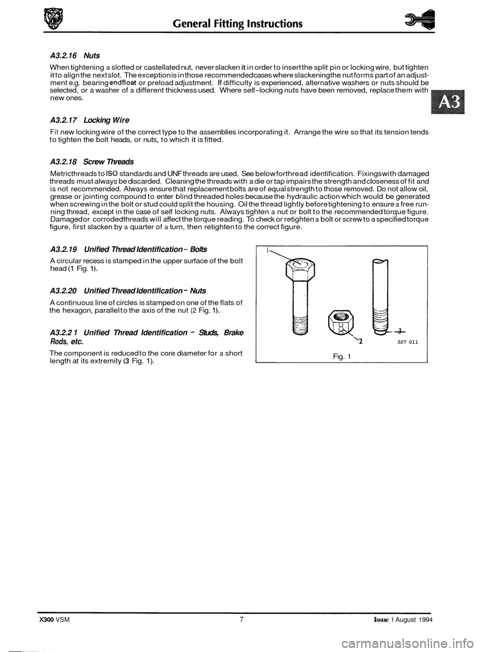
- A3.2.19 Unified Thread Identification - Bolts
A circular recess is stamped in the upper surface of the bolt
head (1 Fig. 1).
A3.2.20 Unified Thread Identification - Nuts
A continuous line of circles is stamped on one of the flats of
the hexagon, parallel to the axis of the nut (2 Fig. 1).
A3.2.2 1 Unified Thread Identification - Studs, Brake
Rods, etc.
The component is reduced to the core diameter for a short
length at its extremity (3 Fig. 1).
A3.2.16 Nuts
When tightening a slotted or castellated nut, never slacken it in order to insert the split pin or locking wire, but tighten
it to align the next slot. The exception is in those recommended cases where slackening the nut forms part of an adjust- ment e.g. bearing endfloat or preload adjustment. If difficulty is experienced, alternative washers or nuts should be
selected, or a washer of a different thickness used. Where self-locking nuts have been removed, replace them with
new ones.
A3.2.17 Locking Wire
Fit new locking wire of the correct type to the assemblies incorporating it. Arrange the wire so that its tension tends
to tighten the bolt heads, or nuts, to which it is fitted.
A3.2.18 Screw Threads
Metricthreads to IS0 standards and UNF threads are used. See below forthread identification. Fixings with damaged
threads must always be discarded. Cleaning the threads with a die or tap impairs the strength and closeness of fit and
is not recommended. Always ensure that replacement bolts are of equal strength to those removed. Do not allow oil,
grease or jointing compound to enter blind threaded holes because the hydraulic action which would be generated
when screwing in the bolt or stud could split the housing. Oil the thread lightly before tightening to ensure
a free run- ning thread, except in the case of self locking nuts. Always tighten a nut or bolt to the recommended torque figure.
Damaged or corroded threads will affect the torque reading. To check or retighten a bolt or screw to a specified torque
figure, first slacken by a quarter of a turn, then retighten to the correct figure.
I
7
-3
‘2 507 011
Fig. 1
X300 VSM 7 Issue 1 August 1994
Page 421 of 521
General Fitting Instructions
I
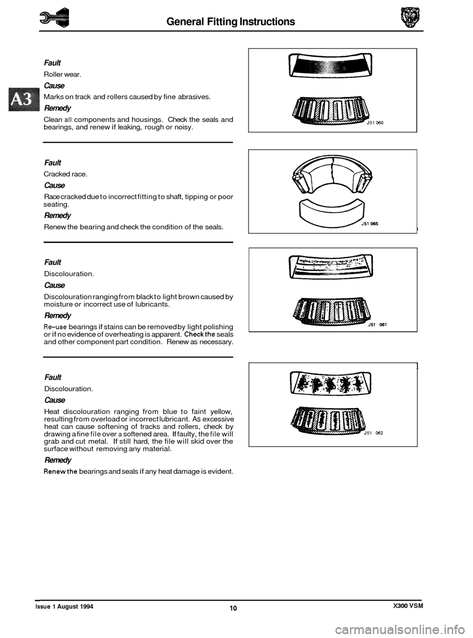
Fault
Roller wear.
Cause
Marks on track and rollers caused by fine abrasives.
Remedy
Clean all components and housings. Check the seals and
bearings, and renew if leaking, rough or noisy.
Fault
Cracked race.
Cause
Race cracked due to incorrect fitting to shaft, tipping or poor
seating.
Remedy
Renew the bearing and check the condition of the seals.
Fault
Discolouration.
Cause
Discolouration ranging from black to light brown caused by
moisture or incorrect use of lubricants.
Remedy
Reuse bearings if stains can be removed by light polishing
or if no evidence of overheating is apparent. Checkthe seals
and other component part condition. Renew as necessary.
51 060
[pzq-j - ..., .... *au
....... ........ e L. U
1
Fault
Discolouration.
Cause
Heat discolouration ranging from blue to faint yellow,
resulting from overload or incorrect lubricant. As excessive
heat can cause softening of tracks and rollers, check by
drawing a fine
file over a softened area. If faulty, the file will
grab and cut metal. If still hard, the file will skid over the
surface without removing any material.
Remedy
Renewthe bearings and seals if any heat damage is evident.
51 062
Issue 1 August 1994 X300 VSM 10
Page 441 of 521

Body Systems & Body Repair
A4.2.3 ZINC COATED PANELS
A4.2.3.1
Description
Approximately 65% of the 'body in white' (BIW) mass is made up of zinc coated panels.
All exterior skin panels, with the exception of the roof, are double side zinc plated and this coating (nominally
7,5 mi- crons) provides corrosion protection in two ways.
1. Should the outer layer of paint become chipped but the zinc coating remain intact, the zinc will oxidize on contact
with air. This coat of oxidation is impermeable and will prevent corrosion damage to the base metal.
2. If both the outer layer of paint and the zinc coating become damaged, the zinc will react with the air and 'sacrifice'
itself to corrosion, rather than the base metal. In this process the zinc is known as a 'sacrificial anode'.
Iynpp: To maintain the protective qualities of the zinc treatment, repairs to any damaged coated area MUST be made as soon as possible after the damage has occurred.
A4.2.3.2 Wdding Preparation
Where 'resistance spot welding' is employed, the zinc coating should be lightly abraded away on the mating surfaces
and those in contact with the electrode tips. Do not remove more of the zinc coating than is absolutely necessary.
Before welding,
a weld-through primer or inter-weld sealer should be applied, as detailed in the Body Sealing and
Preservation man ua I.
Contamination of the weld will occur ifthe plating is not removed, thus making the joint less strong; another side effect
of this will be a greater need for electrode tip dressing and increased tool down time.
In exceptional cases where the plating must remain intact, increase the tip pressure and welding current by 10 to
20%.
Where MIG welding is used as an alternative to resistance spot welding for plug, butt welds, or limited access, the prob- lems caused by the presence of zinc coating are much the same as those previously mentioned. There may also be
the added problems of increased weld spatter and nozzle contamination.
0
A4.2.3.3 Body Fillers
Conventional polyester fillers do not adhere satisfactorily to zinc plated panels. Therefore, it is important to use only
those products specifically designed for this application and follow the manufacturers recommendations.
A4.2.3.4 Refinishing
Use only those products approved by Jaguar Cars Ltd and take special care with zinc coated panels.
Replacement panels are supplied ready primed
so there should be no need for bare metal to be exposed, other than
those areas prepared for welding etc (see 'Welding Preparation' sub section 4.2.3.2).
Where any part of a panel is dressed backto a bare surface, it should be treated with a zinc rich primer compatible with
the chosen paint application system, please refer to section A4.4.1.1.
X300 VSM Issue 1 August 1994 14
Page 443 of 521

Body Systems & Body Repair
A4.2.5 SURFACES (OLD), PREPARE
SRO
77.10.03
Observe all appropriate safety procedures.
WARNINO: DO NOT BURN UNDERSEAL OFF. USE A 'HOT KNIFE' OR SUITABLE SOLVENT
Remove the weld nuggets with a sander and 36 grit disc.
Clean all flanges to a bright smooth finish. (A Fig. 1).
Straighten existing panel joint edges as required.
A4.2.5.1 SURFACES (NEW), PREPARE
SRO 77.10.04
Observe all appropriate safety procedures.
Mark off the area of new panel and cut to size leaving approximately two inches overlap on the existing panel.
Offer up new panel or section, and align with associated parts, i.e. new rear fender aligned with door / luggage com- partment lid / backlight aperture.
Clamp the panel into position.
Where necessary, cut the new and original panels to form a butt joint.
Remove all clamps and the new panel.
rn If required, apply inner panel protection and or sound insulation.
Prepare the new panel joint edges for welding by cleaning to bright metal (A Fig. 1); this includes all interior and
Apply weld-through primer or interweld sealer (6 Fig. 1) to all surfaces to be resistance spot welded.
Where appropriate, apply metal-to-metal adhesive or sealer (C Fig 1) in accordance with the manufacturer's instruc
exterior edges.
tions.
6
C
,,,A'
Fig. 1
0
0
0
X300 VSM Issue 1 August 1994 16
Page 480 of 521
I 03 I Door lock actuators (4 off) 1 part of door assemblv I I
Issue 1 August 1994 X300 VSM 3 I
1 04 I Door lock switches (2 off) I part of door latch assembly I I
1 05 IHoodswitch 1 located above siren I I
1 06 IHorn 1 located on front RH side of en(
1 07 I Inclination sensor I behind luggage compartment LH liner I I
I 08 I Intrusion sensor (LH) I located above LH door behind roof lining I
I 09 I intrusion sensor (RH) 1 located above LH door behind roof lining I
I
1 1 part of door latch assembly I 10 I Key barrel switches (2 off)
1 11 I Key fob transmitter 1 part of key fob I I
I 12 I Key transponder 1 part of key I I
I 13 I Reader exciter coil 1 part of ignition switch I I
I 14 I Reader exciter module 1 part of steering column assembly I I
1 15 I Relays (deadlock) I I I
1 18 I Security active indicator part of central locking switch I I
I 19 I Securitv and lockina control module (SLCM) located in luaaaae compartment behind LH liner I I
1 20 ISounder , located on front RH side of engine bay I I
1 25 IValet switch 1 in centre console compartment I I
A5.2 COMPONENT DESCR/PT/O NS I
stem - RESTRICTED ISSUE
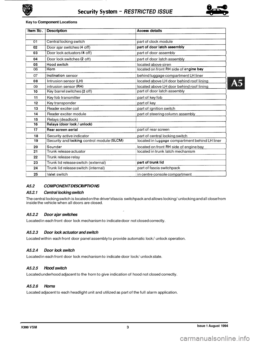
Key to Component Locations
Item No. Description Access details
01 Central locking switch part of clock module
02
1 I
Door ajar switches (4 off)
I I
part of rear screen
I 21 I Trunk release actuator located in trunk latch mechanism
22 I Trunk release relay
23
24 I Trunk lid release switch (external)
I Trunk lid release switch (internal) part of
fascia switchpack ,
A5.2.1 Central locking switch
A5.2.2 Door ajar switches
Located in each front door lock mechanism to indicate door not closed correctly.
-
The central locking switch is located on the driver'sfascia switchpack and allows locking / unlocking and all close from
inside the vehicle when all doors are closed.
A5.2.3
Located within each front door panel assembly to provide automatic lock / unlock operation.
Door lock actuator and switch
A5.2.4 Door lock switch
Located in each front door lock mechanism to indicate door lock/ unlock state.
A5.2.5 Hood switch
Located underhood adjacent to the horn to give indication of hood not closed correctly.
A5.2.6 Horns
Located adjacent to each headlight unit and utilized as part of the full alarm application.
Page 482 of 521
Security System
Pin No. Signal Description
01 0 / P Deadlock (front right / rear left)
02
0 / P Unlock driver's door
03
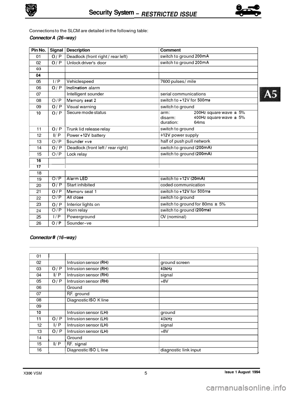
Connections to the SLCM are detailed in the following table:
9 Connector A (26-way)
Comment
switch to ground 200mA
switch to ground 200mA
05 I/P
06
0 / P
07
08 O/P
09
0 / P
10 0 / P Vehiclespeed
7600 pulses
/ mile
Inclination alarm
Intelligent sounder serial communications
Memoryseat2
Visual warning switch to ground
Secure mode status arm:
200Hz square wave f 5%
400Hz square wave f 5%
switch
to
+12V for 500ms
disarm:
duration: 64ms
0
117- I I
11 0 / P Trunk lid release relay 1 switch to ground
12
I / P Power +12V battery 1 + 12V power supply
13 O/P
Sounder+ve half of push pull network
14
0 / P Deadlock
(front left / rear right) switch to ground (200mA)
15 O/P Lock relay switch
to ground (200mA)
18
19
20 21 O/P
AlarmLED switch
to +12V (20mA)
0 / P Start inhibited coded communication
0 / P Memorv seat 1 switch
to +12V for 500ms
Connector 8 (16-way)
22
23
24
25
26 O/P
Allclose switch
to ground
0 / P
O/P Horn relay switch to ground
(200ms)
I/P Powerground OV (nominal)
OJP Sounder-ve
Interior lights
on switch
to ground for 80ms
f 5%
01
I
02
03 04
05
06
07
08
09
I I I I 15 I I / P I R.F. sianal
Intrusion
sensor
(RH) ground screen
0 / P Intrusion sensor (RH) 40kHz
I / P Intrusion sensor (RH) signal
0 / P Intrusion sensor (RH) +8V
Ground
R.F. ground
Diagnostic
IS0 K line
I. I - I 16 I I Diaanostic IS0 L line 1 diagnostic link input
10
11
12
13
14
.I
I I" 1- I
Intrusion sensor (LH) ground
0 / P Intrusion sensor (LH) 40kHz
I / P Intrusion sensor (LH) signal
0 / P Intrusion sensor (LH) +8V
Ground
Issue 1 August 1994 X300 VSM 5
84
- RESTRICTED ISSUE -
Page 485 of 521
Security System - RESTRICTED ISSUE 8-8
-
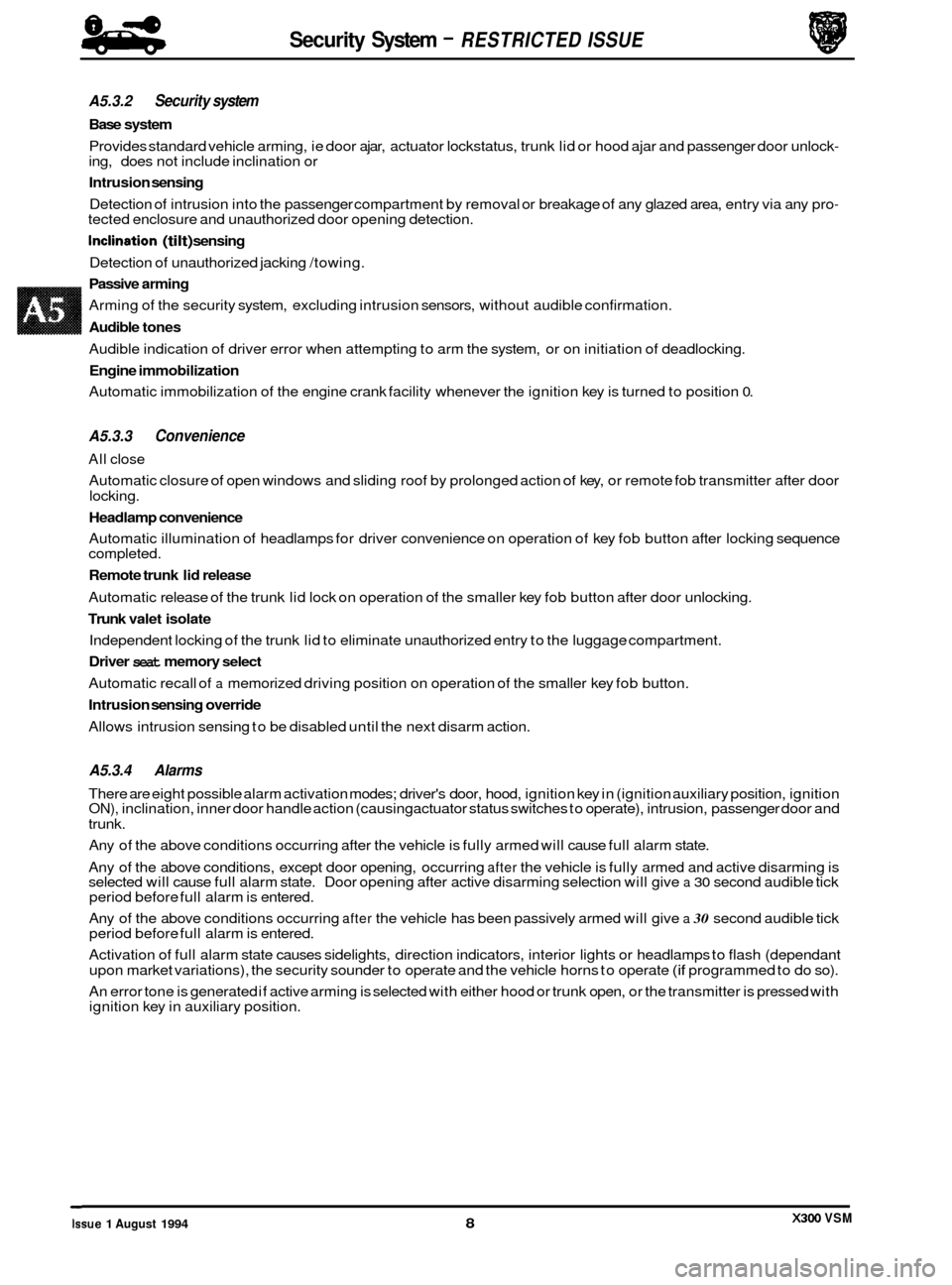
A5.3.2 Security system
Base system
Provides standard vehicle arming, ie door ajar, actuator lockstatus, trunk lid or hood ajar and passenger door unlock- ing, does not include inclination or
Intrusion sensing
Detection of intrusion into the passenger compartment by removal or breakage of any glazed area, entry via any pro- tected enclosure and unauthorized door opening detection.
Inclination (tilt) sensing
Detection of unauthorized jacking /towing.
Passive arming
Arming of the security system, excluding intrusion sensors, without audible confirmation.
Audible tones
Audible indication of driver error when attempting to arm the system, or on initiation of deadlocking.
Engine immobilization
Automatic immobilization of the engine crank facility whenever the ignition key is turned to position 0.
A5.3.3 Convenience
All close
Automatic closure of open windows and sliding roof by prolonged action of key, or remote fob transmitter after door
locking.
Headlamp convenience
Automatic illumination of headlamps for driver convenience on operation of key fob button after locking sequence
completed.
Remote trunk lid release
Automatic release of the trunk lid lock on operation of the smaller key fob button after door unlocking.
Trunk valet isolate
Independent locking of the trunk lid to eliminate unauthorized entry to the luggage compartment.
Driver seat memory select
Automatic recall of a memorized driving position on operation of the smaller key fob button.
Intrusion sensing override
Allows intrusion sensing to be disabled until the next disarm action.
A5.3.4 Alarms
There are eight possible alarm activation modes; driver's door, hood, ignition key in (ignition auxiliary position, ignition ON), inclination, inner door handle action (causing actuator status switches to operate), intrusion, passenger door and
trunk.
Any of the above conditions occurring after the vehicle is fully armed will cause full alarm state.
Any of the above conditions, except door opening, occurring
after the vehicle is fully armed and active disarming is
selected will cause full alarm state. Door opening after active disarming selection will give a 30 second audible tick
period before full alarm is entered.
Any of the above conditions occurring
after the vehicle has been passively armed will give a 30 second audible tick
period before full alarm is entered.
Activation of full alarm state causes sidelights, direction indicators, interior lights or headlamps to flash (dependant
upon market variations), the security sounder to operate and the vehicle horns to operate
(if programmed to do so).
An error tone is generated if active arming is selected with either hood or trunk open, or the transmitter is pressed with
ignition key in auxiliary position.
0
X300 VSM Issue 1 August 1994 8
Page 486 of 521
Jnlock Turn to unlock
position and release VIA I 1st press
Security System - RESTRICTED ISSUE
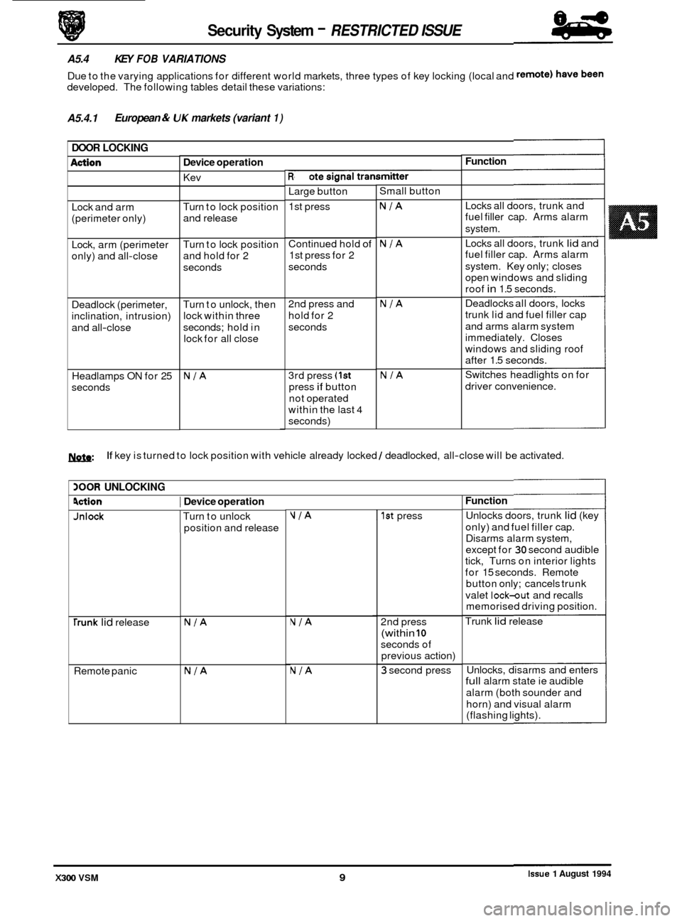
A5.4 KEY FOB VARIATIONS
Due to the varying applications for different world markets, three types of key locking (local and
developed. The following tables detail these variations:
A5.4.1 European & UK markets
(variant 1)
DOOR LOCKING
Function
Device operation
Remote signal transmitter
Kev -
Large button
1st press Small
button
Locks all doors, trunk and
fuel filler cap. Arms alarm
system.
Locks all doors, trunk
lid and
fuel filler cap. Arms alarm
system. Key only; closes
open windows and sliding
roof
in 1.5 seconds.
Deadlocks all doors, locks
trunk lid and fuel filler cap
and arms alarm system
immediately. Closes
windows and sliding roof
after 1.5 seconds.
Switches headlights on for
driver convenience.
Lock
and arm
(perimeter only)
NIA Turn to lock position
and release
Continued hold
of
1st press for 2
seconds NIA
NIA
Lock, arm (perimeter
only) and all
-close Turn
to lock position
and hold for 2
seconds
Deadlock (perimeter,
inclination, intrusion)
and all
-close Turn
to unlock, then
lock within three
seconds; hold in
lock for all close 2nd
press and
hold for 2
seconds
0
Headlamps ON for 25
seconds 3rd
press (1st
press if button
not operated
within the last
4
seconds)
NIA NIA
1ynfn: If key is turned to lock position with vehicle already locked / deadlocked, all-close will be activated.
BOOR UNLOCKING
Function
Unlocks doors, trunk lid (key
only) and fuel filler cap.
Disarms alarm system,
except for
30 second audible
tick, Turns on interior lights
for 15 seconds. Remote
button only; cancels trunk
valet
lock-out and recalls
memorised driving position.
Trunk
lid release
9ction I Device operation
0
0
NIA 2nd press
(within 10
seconds of
previous action)
NIA
NIA
rrunk lid release
Remote panic
NIA 3 second press Unlocks,
disarms and enters full alarm state ie audible
alarm (both sounder and
horn) and visual alarm
(flashing lights).
Issue 1 August 1994 X300 VSM 9
Page 487 of 521
Security System - RESTRICTED ISSUE
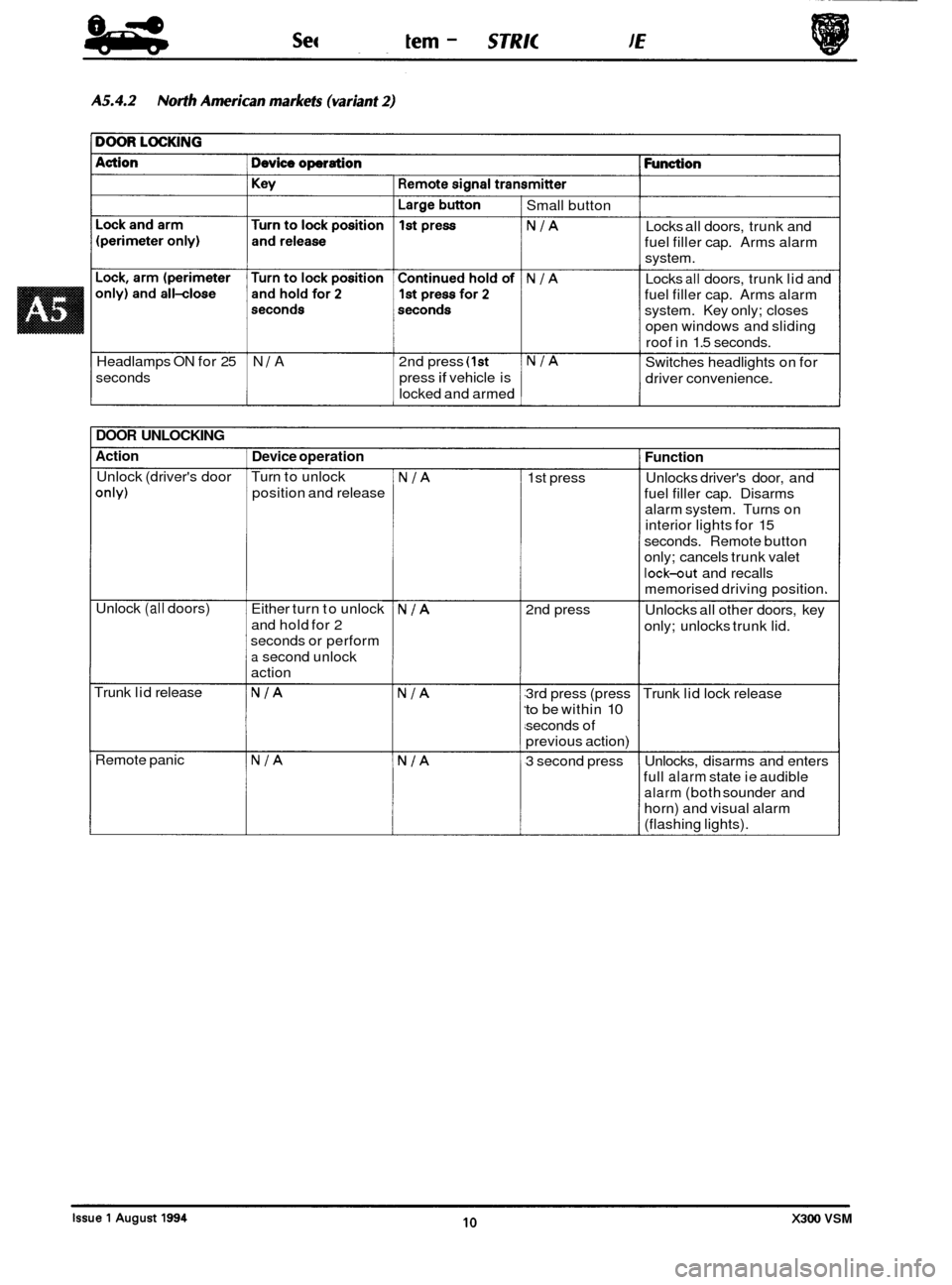
Headlamps ON for 25 N 1 A 2nd press (1st
seconds press if vehicle is
locked and armed Small
button
NIA Locks all doors, trunk and
fuel filler cap. Arms alarm
system.
Locks
all doors, trunk lid and
fuel filler cap. Arms alarm
system. Key only; closes
open windows and sliding
roof in 1.5 seconds.
NIA Switches headlights on for
driver convenience.
NIA
DOOR UNLOCKING
Action
Unlock (driver's door
only)
Unlock (all doors)
Trunk lid release
Remote panic
Device operation
Turn to unlock
position and release
Either turn to unlock
and hold for 2
seconds or perform
a second unlock
action
NIA
NIA
NIA
NIA
NIA
NIA
1st press
2nd press
3rd press (press
to be within 10
seconds of
previous action)
3 second press
Function
Unlocks driver's door, and
fuel filler cap. Disarms
alarm system. Turns on
interior lights for 15
seconds. Remote button
only; cancels trunk valet
lock-out and recalls
memorised driving position.
Unlocks all other doors, key
only; unlocks trunk lid.
Trunk lid lock release
Unlocks, disarms and enters
full
alarm state ie audible
alarm (both sounder and
horn) and visual alarm
(flashing lights).
10 X300 VSM
Page 488 of 521
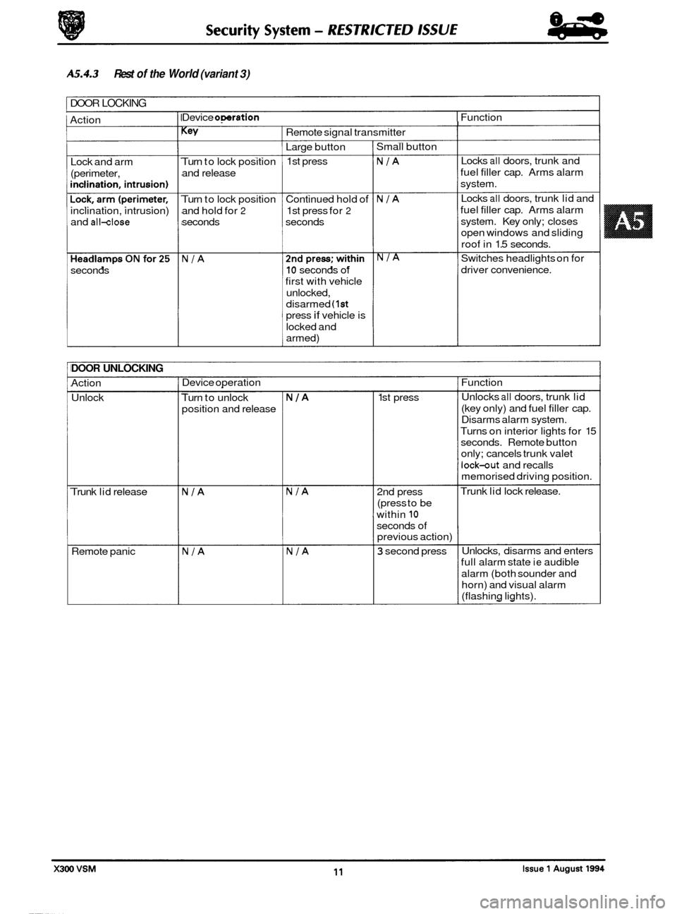
A5.4.3
I DOOR LOCKING
Rest of the World (variant 3)
-
1 Action Lock and arm
(perimeter,
inclination, intrusion)
and
all-close
seconds Device
omration I Function I Key I Remote
signal transmitter
Large button
1st press
Turn to lock position
and release
Turn to lock position Continued hold of
and hold for
2 1st press for 2
seconds seconds
NIA 10 seconds of
first with vehicle
unlocked,
disarmed
(1st
press if vehicle is
locked and
armed) Small
button
NIA Locks all doors, trunk and
fuel filler cap. Arms alarm
system.
Locks
all doors, trunk lid and
fuel filler cap. Arms alarm
system. Key only; closes
open windows and sliding
roof in 1.5 seconds.
NIA Switches headlights on for
driver convenience.
NIA
DOOR UNLOCKING
Action
Unlock
Trunk lid release
Remote panic Device
operation I Function
Turn to unlock
position and release
NIA
NIA
NIA
NIA
NIA
1 st press Unlocks all doors,
trunk lid
(key only) and fuel filler cap.
Disarms alarm system.
Turns on interior lights for 15
seconds. Remote button
only; cancels trunk valet
lock-out and recalls
memorised driving position.
Trunk lid lock release.
2nd press
(press to be
within
10
seconds of
previous action)
3 second press Unlocks,
disarms and enters
full alarm state
ie audible
alarm (both sounder and
horn) and visual alarm
(flashing lights).