jacking JAGUAR XJ6 1994 2.G Workshop Manual
[x] Cancel search | Manufacturer: JAGUAR, Model Year: 1994, Model line: XJ6, Model: JAGUAR XJ6 1994 2.GPages: 521, PDF Size: 17.35 MB
Page 30 of 521
.
e
SECTION CONTENTS
Sub-section Title
i ................ Preliminary Page ............................................
2.1 .............. Jacking And Lifting ...........................................
2.1.1 ............. Jacking And Lifting. Safety Precautions ..........................
2.1.2 ............. Jacking And Lifting. Jacking Points ..............................
2.1.3 ............. Jacking And Lifting. Wheel Free Lift .............................
2.1.4 ............. Jacking And Lifting. Workshop Jacks ............................
2.1.4.1 ........... Jacking And Lifting. Workshop Jacks. Front - One Wheel ...........
2.1.4.2 ........... Jacking And Lifting. Workshop lacks. Front - Both Wheels ..........
2.1.4.3 ........... Jacking And Lifting. Workshop Jacks. Rear - Both Wheels ...........
2.2 .............. Vehicle Recovery ............................................
2.2.1. ............ Vehicle Recovery, General .....................................
2.2.2 .............
2.2.3 ............. Vehicle Recovery, Gear-shift Interlock - Manual Override .........
2.2.4 ............. Vehicle Recovery, Transporting .................................
2.2.5 ............. Vehicle Recovery, Towing Recovery .............................
2.2.6 ............. Vehicle Recovery, Vehicles With Defective Automatic Transmission ..
2.2.7. ............ Vehicle Recovery, Suspended Towing ...........................
2.2.8. ............ Vehicle Recovery, Rear Suspended Tow ..........................
Vehicle Recovery, Gear-shift Interlock ..........................
..
..
..
..
..
..
..
..
..
..
..
..
..
..
..
..
..
..
X300 VSM i
SRO
......
......
......
......
......
......
......
......
......
......
......
......
......
......
......
......
......
......
.
......
......
......
......
......
......
......
......
......
......
......
......
......
......
......
......
......
......
......
......
......
......
......
......
......
......
......
......
......
......
......
......
......
......
......
......
. Issue 1
Page
.... i
.... i
.... 1
.... 1
.... 1
.... 2
.... 2
.... 2
.... 2
.... 3
.... 3
.... 3
.... 3
.... 4
.... 4
.... 4
.... 5
.... 5
August 1994
Page 32 of 521
0 2.1 JACKING AND LIFTING
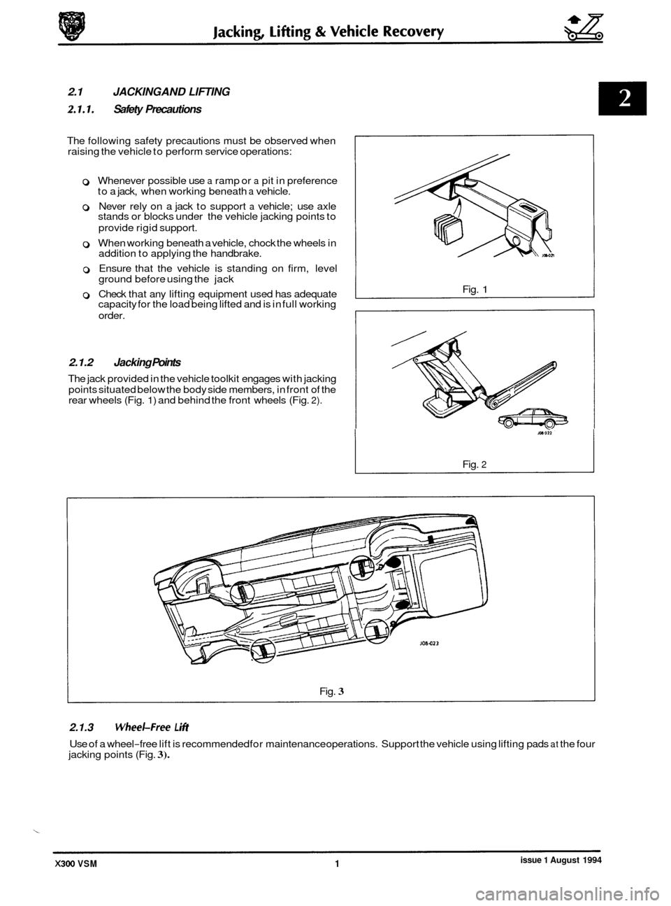
2.1.1. Safety Precautions
The following safety precautions must be observed when
raising the vehicle to perform service operations:
0 Whenever possible use a ramp or a pit in preference
to a jack, when working beneath a vehicle.
0 Never rely on a jack to support a vehicle; use axle
stands or blocks under the vehicle jacking points to
provide rigid support.
0 When working beneath a vehicle, chock the wheels in
addition to applying the handbrake.
0 Ensure that the vehicle is standing on firm, level
ground before using the jack
0 Check that any lifting equipment used has adequate
capacity for the load being lifted and is in full working
order.
2.1.2 Jacking Points
The jack provided in the vehicle toolkit engages with jacking
points situated below the body side members, in front of the
rear wheels (Fig.
1) and behind the front wheels (Fig. 2).
Fig. 1
Fig. 2
Fig. 3
2.1.3 WheeLFree L i#t
Use of a wheel-free lift is recommended for maintenance operations. Support the vehicle using lifting pads at the four
jacking points (Fig. 3).
issue 1 August 1994 X300 VSM 1
Page 33 of 521
gg Jacking, Lifting & Vehicle Recovery
.-
- 2.1.4.1
Front - One Wheel
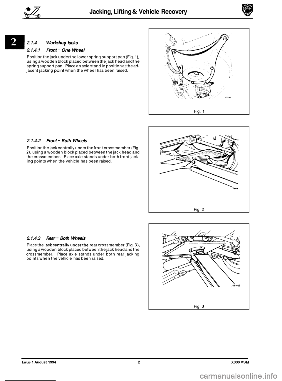
Position the jack under the lower spring support pan (Fig. I), using a wooden block placed between the jack head and the
spring support pan. Place an axle stand
in position at the ad- jacent jacking point when the wheel has been raised.
2.1.4.2 Front - Both Wheels
Position the jack centrally under the front crossmember (Fig. 2), using a wooden block placed between the jack head and
the crossmember. Place axle stands under both front jack- ing points when the vehicle has been raised.
2.1.4.3 Rear - Both Wheels
Place the jackcentrally underthe rear crossmember (Fig. 3), using a wooden block placed between the jack head and the
crossmember. Place axle stands under both rear jacking
points when the vehicle has been raised.
I 2.1.4 WorkshoD lacks
Fig. 1
Fig. 2
Fig. 3
Issue 1 August 1994 2 X300 VSM
Page 35 of 521
gg Jacking, lifting & Vehicle Recovery
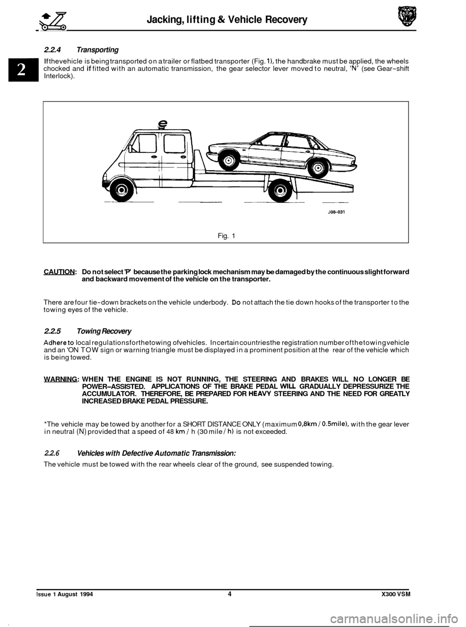
2.2.4 Transporting
If thevehicle is being transported on a trailer or flatbed transporter (Fig. I), the handbrake must be applied, the wheels
chocked and if fitted with an automatic transmission, the gear selector lever moved to neutral, 'N' (see Gear-shift
Interlock).
e
JOS-031
Fig. 1
CAUTION: Do not select 'P' because the parking lock mechanism may be damaged by the continuous slight forward
and backward movement of the vehicle on the transporter.
There are four tie-down brackets on the vehicle underbody. Do not attach the tie down hooks of the transporter to the
towing eyes of the vehicle.
2.2.5 Towing Recovery
Adhereto local regulationsforthetowing ofvehicles. In certain countriesthe registration number ofthetowing vehicle
and an 'ON TOW sign or warning triangle must be displayed in a prominent position at the rear of the vehicle which
is being towed.
WARNING: WHEN THE ENGINE
IS NOT RUNNING, THE STEERING AND BRAKES WILL NO LONGER BE
ACCUMULATOR. THEREFORE, BE PREPARED FOR
HEAVY STEERING AND THE NEED FOR GREATLY
INCREASED BRAKE PEDAL PRESSURE.
POWER-ASSISTED.
APPLICATIONS
OF THE BRAKE PEDAL WILL GRADUALLY DEPRESSURIZE THE
*The vehicle may be towed by another for a SHORT DISTANCE ONLY (maximum
0,8km / O.Smile), with the gear lever
in neutral (N) provided that a speed of 48 km / h (30 mile / h) is not exceeded.
2.2.6
The vehicle must be towed with the rear wheels clear of the ground, see suspended towing.
Vehicles with Defective Automatic Transmission:
Issue 1 August 1994 4 X300 VSM
Page 36 of 521
Jacking, lifting & Vehicle Recovery gg
2.2.7 Suspended Towing
CAUTION: Do not tow with sling-type equipment as damage to the bodywork may result. Do not front suspend tow vehides with automatic transmission.
2.2.8 Rear Suspended Tow
Remove the ignition key from the ignition /steering lock.
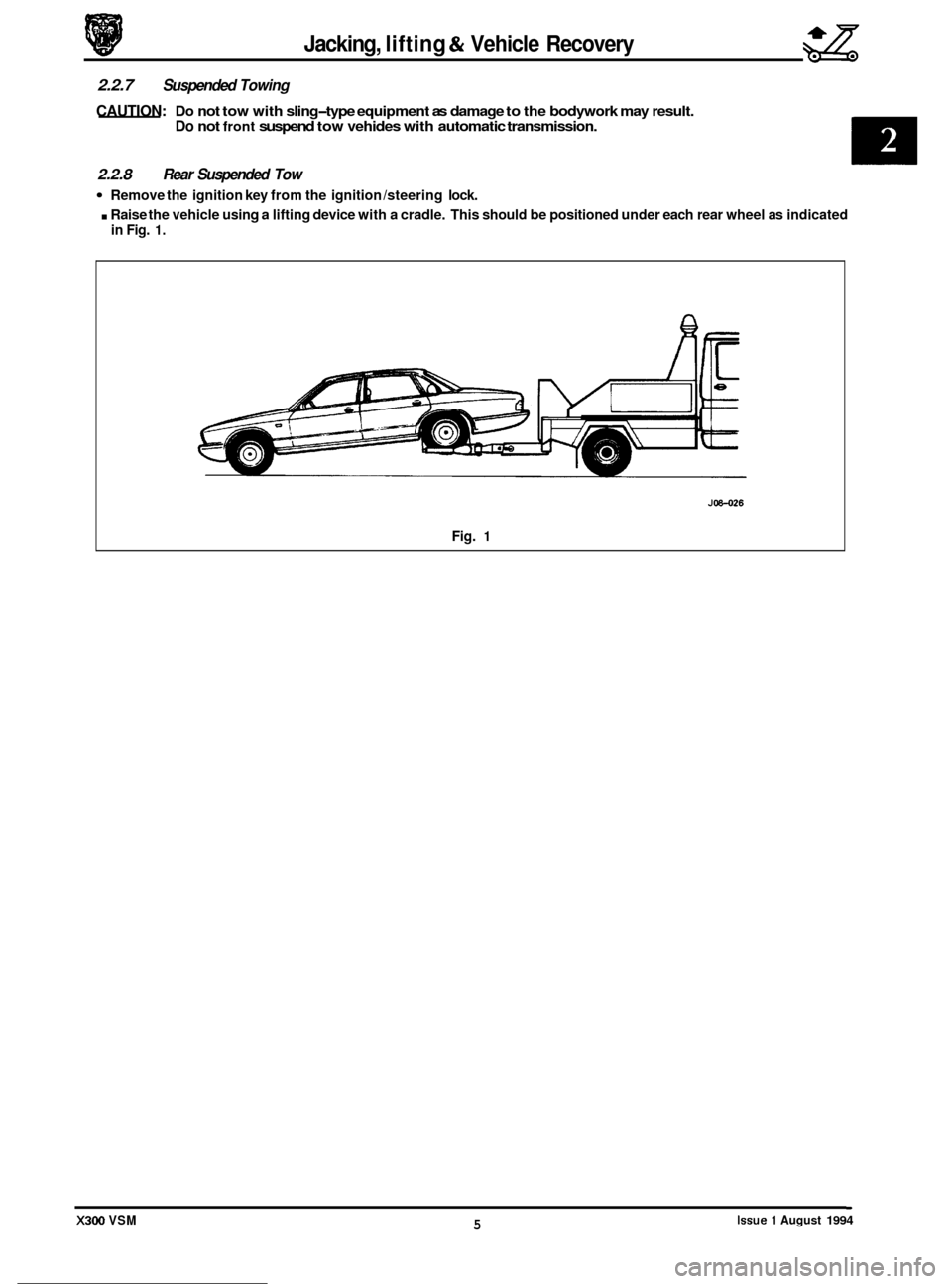
. Raise the vehicle using a lifting device with a cradle. This should be positioned under each rear wheel as indicated
in Fig. 1.
0
0
0
J08-026
Fig. 1
Issue 1 August 1994 5 X300 VSM
Page 119 of 521
Manual Transmission & Clutch (AJ16)
7.1.2 MANUAL TRANSMISSION ASSEMBLY, RENEW
SRO 37.20.01
. Disconnect the battery.
. Remove inlet manifold rear securing nuts.
. Remove injector harness mounting bracket.
. Fit lifting bracket 18G 1465 and secure with the nuts.
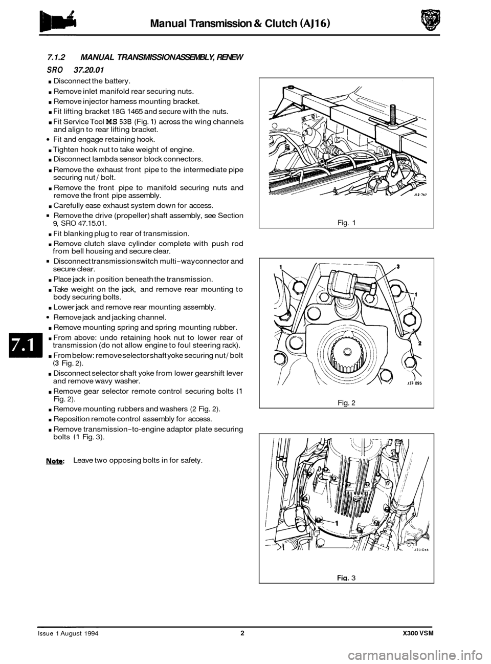
. Fit Service Tool MS 536 (Fig. 1) across the wing channels
Fit and engage retaining hook.
. Tighten hook nut to take weight of engine.
. Disconnect lambda sensor block connectors.
. Remove the exhaust front pipe to the intermediate pipe
securing nut / bolt.
. Remove the front pipe to manifold securing nuts and
remove the front pipe assembly.
. Carefully ease exhaust system down for access.
Remove the drive (propeller) shaft assembly, see Section
. Fit blanking plug to rear of transmission.
. Remove clutch slave cylinder complete with push rod
Disconnect transmission switch multi-way connector and
. Place jack in position beneath the transmission.
. Take weight on the jack, and remove rear mounting to
. Lower jack and remove rear mounting assembly.
Remove jack and jacking channel.
. Remove mounting spring and spring mounting rubber.
. From above: undo retaining hook nut to lower rear of
transmission (do not allow engine to foul steering rack).
. From below: remove selector shaft yoke securing nut / bolt (3 Fig. 2).
. Disconnect selector shaft yoke from lower gearshift lever
and remove wavy washer.
. Remove gear selector remote control securing bolts (1 Fig. 2).
. Remove mounting rubbers and washers (2 Fig. 2).
. Reposition remote control assembly for access.
. Remove transmission-to-engine adaptor plate securing
and
align to rear lifting bracket.
9, SRO 47.15.01.
from bell housing and secure clear.
secure clear.
body securing bolts.
bolts
(1 Fig. 3).
N.&: Leave two opposing bolts in for safety.
Fig. 1
Fig.
2
Fig. 3 ~ ~ ~~ ~
Issue 1 August 1994 2 X300 VSM
Page 120 of 521
Manual Transmission & Clutch (AJ16)
. Remove front clamp from unit lift.
. Raise / lower unit with jack, no stands.
. Traverse lift under ramp and take weight of transmission.
. Adjust jacking platform angles to suit transmission.
. Adjust side and rear clamps to suit transmission and tighten clamp wing nuts.
. Fit the safety chain assembly to left hand arm of lift, and secure with peg.
Pass safety chain over transmission and engage in front arm of lift. Tighten the safety chain adjuster.
. Remove remaining transmission to adaptor plate securing bolts and carefully lower transmission from engine.
. Remove transmission from ramp area.
. Remove clutch release bearing assembly from release lever.
. Remove clutch release lever retaining clip and remove lever.
. Remove release lever pivot pin.
Remove transmission switch.
. Remove rear mounting spring retainer securing nut.
. Reposition selector shaft pin cover.
0
Remove rear mounting spring retainer and remove rear mounting assembly.
Remove selector shaft yoke to selector shaft retaining pin and remove the yoke.
. Remove slave cylinder securing studs.
. Remove the transmission from the unit lift.
. Remove transmission drain plug and allow to drain, refit
the drain plug.
Fit new transmission to unit lift.
Fill transmission with oil and refit the level plug.
. Clean components and mating faces.
. Fit the slave cylinder mounting studs.
. Lubricate the selector output shaft.
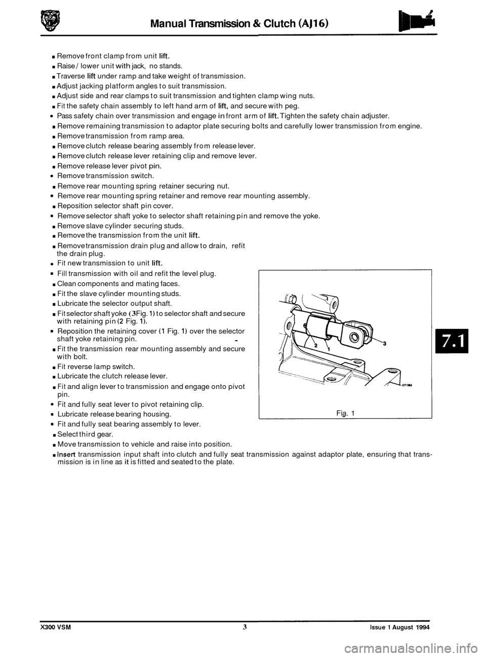
. Fit selector shaft yoke (3 Fig. 1) to selector shaft and secure
with retaining pin (2 Fig. 1).
Reposition the retaining cover (1 Fig. 1) over the selector
shaft yoke retaining pin. -
. Fit the transmission rear mounting assembly and secure
with bolt.
. Fit reverse lamp switch.
. Lubricate the clutch release lever.
. Fit and align lever to transmission and engage onto pivot
pin.
Fit and fully seat lever to pivot retaining clip.
= Lubricate release bearing housing.
9 Fit and fully seat bearing assembly to lever.
. Select third gear.
. Move transmission to vehicle and raise into position.
Fia. 1
. Insert transmission input shaft into clutch and fully seat transmission against adaptor plate, ensuring that trans- mission is in line as it is fitted and seated to the plate.
X300 VSM 3 Issue 1 August 1994
Page 412 of 521
used.
WARNING: FUME EXTRACTION EQUIPMENT MUST BE IN OPERATION WHEN SOLVENTS ARE USED E.G.
TRICHLOROETHANE, WHITE SPIRIT, SBPB, METHYLENE CHLORIDE, PERCHLORETHYLENE.
DO NOT SMOKE IN THE VICINITY OF VOLATILE DEGREASING AGENTS.
Adhere strictly to handling and safety instructions given on containers and labels. Keep oils and solvents away from
naked flames and other sources of ignition. Do not apply heat in an attempt to free seized nuts or fittings; as well as
causing damage to protective coatings, there is
a risk of damage from stray heat to electronic equipment and brake
lines. Do not leave tools, equipment, spilt oil etc. around or on work
area. Wear protective overalls and use barrier
cream when necessary.
0 A3.1.1 Used Engine Oils
Prolonged and repeated contact with mineral oil will result in the removal of natural oils from the skin, leading to dry- ness, irritation and dermatitis. In addition, used engine oil contains potentially harmful contaminants which may cause
skin cancer. Washing facilities and adequate means of skin protection should be provided.
A3.1.2 Health Protection Precautions
0 Avoid prolonged and repeated contact with oil; particularly used engine oils.
o Wear protective clothing, including impervious gloves where practicable
0 Do not put oily rags in pockets.
0 Avoid contaminating clothes, particularly underwear, with oil.
0 Overalls must be cleaned regularly. Discard unwashable clothing and footwear which is oil impregnated.
o First Aid treatment should be obtained immediately for open cuts or wounds.
0 Use barrier creams, applying before each work period, to enable easier removal of dirty oil / grease from the
skin.
0 Wash with soap and water to ensure that all oil is removed (skin cleaner and a nail brush will help). The use of
preparations containing lanolin will help to replace the natural skin oils which have been removed.
o Do not use petrol, kerosene, gas oil, thinners or solvents for washing skin.
0 If skin disorders develop, obtain medical advice immediately.
0 Where practicable, degrease components prior to handling.
0 Where there is a risk of fluids coming into contact with the eyes, eye protection should be worn, for example,
goggles or a face shield. An eye wash facility should be provided.
A3.1.3 Environmental Protection Precautions
A3.1 SAFETY PRECAUTIONS
Whenever possible, use a ramp or pit whilst working beneath a car, in preference to jacking. Position chocks at the
wheels as well as applying the handbrake. Never rely on a jack alone to support a car. Use axle stands, or blocks care- fully placed at the jacking points, to provide a rigid location. Checkthat any lifting equipment used has adequate capac- ity and is fully serviceable. Ensure that a suitable form of fire extinguisher is conveniently located.
When using
electrical tools and equipment, inspect the power lead for damage and check that it is properly earthed. Disconnect
the earth (grounded) terminal of the car battery. Do not disconnect any pipes of the air conditioning refrigeration sys-
tem unless you are trained and instructed to do so. A refrigerant is used which can cause blindness if allowed to come
into contact with the eyes. Ensure that adequate ventilation is provided when volatile degreasing agents are being
It is illegal to pour used oil on to the ground, down sewers or drains, or into water courses. The burning of used engine
oil in small space heaters or boilers is not recommended unless emission control equipment is fitted. Dispose of used
oil through authorized waste disposal contractors, to licensed waste disposal sites or to the waste oil reclamation trade.
If in doubt, contact the Local Authority for advice on disposal facilities.
X300 VSM 1 Issue 1 August 1994
Page 481 of 521
84
- Security System - RESTRICTED /SSU€
A5.2.7 Inclination sensor
Located adjacent to the SLCM underthe luggage compartment LH side linerto give indication of unauthorized jacking / lifting of the vehicle.
A5.2.8 Intrusion sensors
Located above each front door to give indication of unauthorized entry into the vehicle passenger compartment.
A5.2.9 Reader exciter coil
Forms an integral part of the ignition switch to prove correct key insertion by communicating key transponder signal
to control module.
A5.2.10 Reader exciter module
Located on the steering column to receive signals from the reader/ exciter coil and disarm the engine immobilization
system on correct demand.
A5.2.11 Security active indicator
An LED built into the central locking switch to indicate when security system is armed.
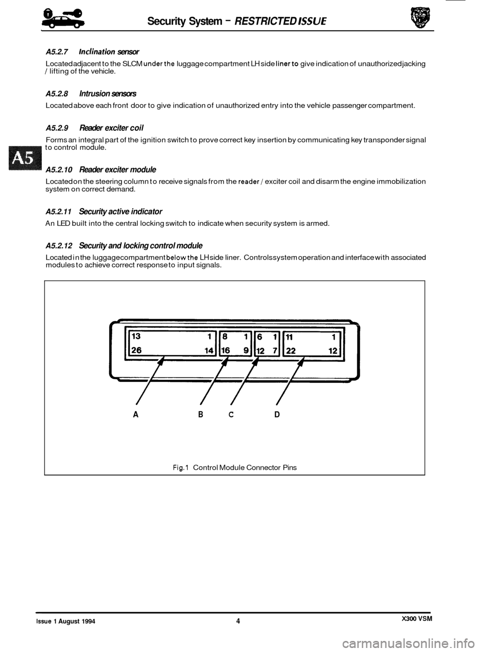
A5.2.12 Security and locking control module
Located in the luggage compartment belowthe LH side liner. Controls system operation and interface with associated
modules to achieve correct response to input signals.
L
Fig.1 Control Module Connector Pins
/ // /
A B C D
X300 VSM Issue 1 August 1994 4
Page 485 of 521
Security System - RESTRICTED ISSUE 8-8
-
A5.3.2 Security system
Base system
Provides standard vehicle arming, ie door ajar, actuator lockstatus, trunk lid or hood ajar and passenger door unlock- ing, does not include inclination or
Intrusion sensing
Detection of intrusion into the passenger compartment by removal or breakage of any glazed area, entry via any pro- tected enclosure and unauthorized door opening detection.
Inclination (tilt) sensing
Detection of unauthorized jacking /towing.
Passive arming
Arming of the security system, excluding intrusion sensors, without audible confirmation.
Audible tones
Audible indication of driver error when attempting to arm the system, or on initiation of deadlocking.
Engine immobilization
Automatic immobilization of the engine crank facility whenever the ignition key is turned to position 0.
A5.3.3 Convenience
All close
Automatic closure of open windows and sliding roof by prolonged action of key, or remote fob transmitter after door
locking.
Headlamp convenience
Automatic illumination of headlamps for driver convenience on operation of key fob button after locking sequence
completed.
Remote trunk lid release
Automatic release of the trunk lid lock on operation of the smaller key fob button after door unlocking.
Trunk valet isolate
Independent locking of the trunk lid to eliminate unauthorized entry to the luggage compartment.
Driver seat memory select
Automatic recall of a memorized driving position on operation of the smaller key fob button.
Intrusion sensing override
Allows intrusion sensing to be disabled until the next disarm action.
A5.3.4 Alarms
There are eight possible alarm activation modes; driver's door, hood, ignition key in (ignition auxiliary position, ignition ON), inclination, inner door handle action (causing actuator status switches to operate), intrusion, passenger door and
trunk.
Any of the above conditions occurring after the vehicle is fully armed will cause full alarm state.
Any of the above conditions, except door opening, occurring
after the vehicle is fully armed and active disarming is
selected will cause full alarm state. Door opening after active disarming selection will give a 30 second audible tick
period before full alarm is entered.
Any of the above conditions occurring
after the vehicle has been passively armed will give a 30 second audible tick
period before full alarm is entered.
Activation of full alarm state causes sidelights, direction indicators, interior lights or headlamps to flash (dependant
upon market variations), the security sounder to operate and the vehicle horns to operate
(if programmed to do so).
An error tone is generated if active arming is selected with either hood or trunk open, or the transmitter is pressed with
ignition key in auxiliary position.
0
X300 VSM Issue 1 August 1994 8