buttons JAGUAR XJ6 1994 2.G Workshop Manual
[x] Cancel search | Manufacturer: JAGUAR, Model Year: 1994, Model line: XJ6, Model: JAGUAR XJ6 1994 2.GPages: 521, PDF Size: 17.35 MB
Page 328 of 521
Climate Control Systems
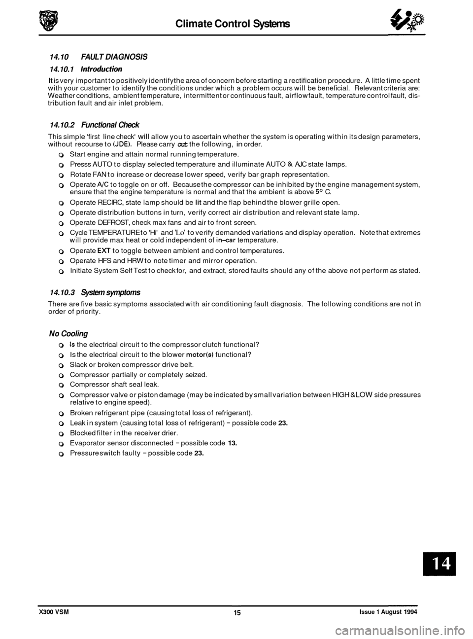
14.10 FAULT DIAGNOSIS
14.10.1 Introduction
It is very important to positively identifythe area of concern before starting a rectification procedure. A little time spent
with your customer to identify the conditions under which a problem occurs will be beneficial. Relevant criteria are:
Weather conditions, ambient temperature, intermittent or continuous fault, airflow fault, temperature control fault, dis
- tribution fault and air inlet problem.
14.10.2 Functional Check
This simple 'first line check' will allow you to ascertain whether the system is operating within its design parameters,
without recourse to (JDE). Please carry out the following, in order.
0 Start engine and attain normal running temperature.
0 Presss AUTO to display selected temperature and illuminate AUTO & AJC state lamps.
0 Rotate FAN to increase or decrease lower speed, verify bar graph representation.
0 Operate AJC to toggle on or off. Because the compressor can be inhibited by the engine management system,
ensure that the engine temperature is normal and that the ambient is above 5O C.
0 Operate RECIRC, state lamp should be lit and the flap behind the blower grille open.
0 Operate distribution buttons in turn, verify correct air distribution and relevant state lamp.
0 Operate DEFROST, check max fans and air to front screen.
0 Cycle TEMPERATURE to 'Hi' and 'Lo' to verify demanded variations and display operation. Note that extremes
will provide max heat or cold independent of in-car temperature.
0 Operate EX to toggle between ambient and control temperatures.
0 Operate HFS and HRW to note timer and mirror operation.
0 Initiate System Self Test to check for, and extract, stored faults should any of the above not perform as stated.
14.10.3 System symptoms
There are five basic symptoms associated with air conditioning fault diagnosis. The following conditions are not in order of priority.
No Cooling
0 Is the electrical circuit to the compressor clutch functional?
0 Is the electrical circuit to the blower motor(s) functional?
0 Slack or broken compressor drive belt.
0 Compressor partially or completely seized.
0 Compressor shaft seal leak.
0 Compressor valve or piston damage (may be indicated by small variation between HIGH &LOW side pressures
relative to engine speed).
0 Broken refrigerant pipe (causing total loss of refrigerant).
0 Leak in system (causing total loss of refrigerant) - possible code 23.
0 Blocked filter in the receiver drier.
0 Evaporator sensor disconnected - possible code 13.
0 Pressure switch faulty - possible code 23.
X300 VSM Issue 1 August 1994
Page 477 of 521
page e
Sub-Section Title SRO
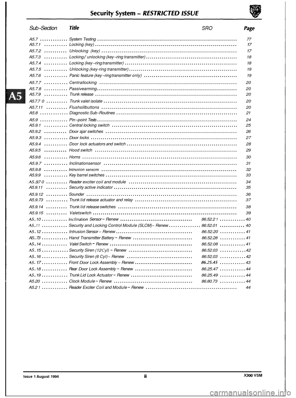
A5.7 ............. System Testing ...................................................................... 77
A5.7.1
........... Locking (key) ....................................................................... \
17
A5.7.2 ........... Unlocking (key) .................................................................... 17
A5.7.3 ........... Locking / unlocking (key-ring transmitter) ............................................... 18
A5.7.4
........... Locking (key-ring transmitter) ......................................................... 18
A5.7.5
........... Unlocking (key-ring transmitter) ....................................................... 19
A5.7.6
........... Panic feature (key-ring transmitter only) ................................................ 19
A5.7.7
........... Centrallocking ..................................................................... 20
A5.7.8
........... Passivearming ...................................................................... 20
A5.7.9
........... Trunk release ....................................................................... \
20
A5.7.7
0 .......... Trunk valet isolate ................................................................... 20
A5.7.11
.......... Flushsillbuttons .................................................................... 20
A5.9
............. Pin-point Tests ...................................................................... 24
A5.8
............. Diagnostic
Sub-Routines ............................................................. 21
A5.9.1
........... Central locking switch ............................................................... 25
A5.9.2
........... Door ajar switches .................................................................. 26
A5.9.3
........... Door locks ........................................................................\
. 27
A5.9.4
........... Door lock actuators and switch ........................................................ 28
A5.9.5
........... Hood switch ....................................................................... \
29 e
A5.9.6 ........... Horns ........................................................................\
..... 30
A5.9.7
........... Inclinationsensor ................................................................... 31
A5.9.8
........... Intrusionsensors .................................................................... 32
A5 . 9.7 0 .......... Reader exciter coil and module ....................................................... 34
A5.9.12
.......... Sounder ........................................................................\
... 36
A5.9.14
.......... Trunk lid release switches ............................................................ 38
A5.9.15
.......... Valetswitch ........................................................................\
39
A5 . 10 ............ Inclination Sensor - Renew ...................................... 86.52.2 1 ............ 40
A5 . 12 ............ Intrusion Sensor - Renew ........................................ 86.52.20 ............ 41
A5 . 14 ............ Valet Switch - Renew ........................................... 86.52.08 ............ 41
A5.9.9
........... Key
barrel switches .................................................................. 33
A5.9.11
.......... Security active indicator .............................................................. 35
A5.9.73
.......... Trunk lid release actuator and relay .................................................... 37
A5 . 11 ............ Security and Locking Control Module (SLCM) - Renew ............... 86.52.01 ............ 40
AS
. 73 ............ Hand Transmitter Battery - Renew ................................ 86.52.28 ............ 41
A5 . 15 ............ Security Siren (12 Cyl) - Renew .................................. 86.52.03 ............ 42
A5 . 16 ............ Security Siren (6 Cyl) - Renew ................................... 86.52.03 ............ 42
A5 . 17 ............ Front Door Lock Assembly - Renew ............................... 86.25.45 ............ 43
A5 . 18 ............ Rear Door Lock Assembly - Renew ............................... 86.25.47 ............ 44
Trunk Lid Lock Actuator - Renew ................................. 86.25.49 ............ 44
Clock Module - Renew ......................................... 86.80.73 ............ 44
Reader Exciter Coil and Module - Renew ............................................... 44
e
A5 . 19 ............
A5.20 ............
A5.2 1 ............
e
X300 VSM Issue 1 August 1994 ii
Page 478 of 521
0
c
doors, windows, trunk, hood and sliding roof.
I Method I UK / EUROPE
of IXJ16I1SOVIIDAIM
Operation Sport XJ12 /DD6
Locking
Central locking Key X X X
Remote central locking Remote X X X
Deadlocking Remote/ X X X
Two stage unlock Remote/
- - - Key
Key
Drive away locks Auto X/DD X/DD X/DD
Switch
close
Interior trunk lid release Switch
Flush
sill buttons /
intrusion override
security
Security system (base)
Intrusion sensing (full)
Inclination sensing
Passive arming
Panic alarm
Audible tones (error
/
deadlock)
Engine immobilization
*
Auto
.,,,
Remote
Auto
1 XI X X
X D
D D
X/ DD
X
-~~
Security System - RESTRICTED ISSUE
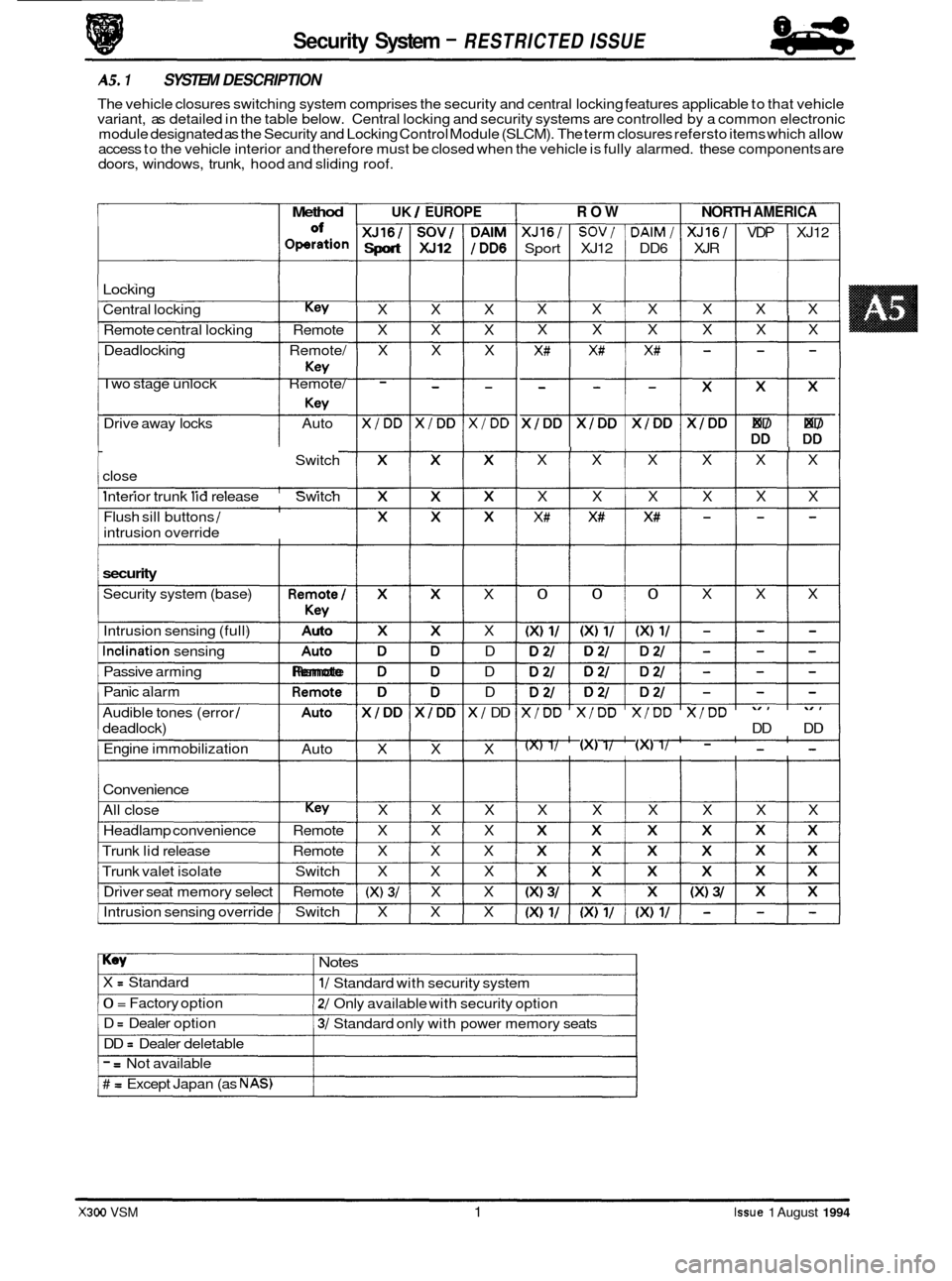
AS. 1 SYSTEM DESCRIPTION
The vehicle closures switching system comprises the security and central locking features applicable to that vehicle
variant, as detailed in the table below. Central locking and security systems are controlled by a common electronic
module designated as the Security and Locking Control Module (SLCM). The term closures refersto items which allow
access to the vehicle interior and therefore must be closed when the vehicle is fully alarmed. these components are
Convenience
All close Key X X X
Headlamp convenience Remote X X X
Trunk lid release Remote X X X
Trunk valet isolate Switch X X X
Driver seat memory select Remote
(X) 3/ X X
Intrusion sensing override Switch X X X
ROW NORTH AMERICA
XJ16/ SOV/ DAlM/ XJ16/ VDP XJ12
Sport XJ12 DD6 XJR
X X X X X X
I X X X X X X
X# X# X# - - -
$$$$$ DD DD
I I I I I X X X X X X
X X X X X X
X# X# X# - - -
I 0 0 0 X X X
X/DD X/DD X/DD X/DD
DD DD
(X) 1/ (XI 1/ (XI 1/ - - -
X X X X X X
Key Notes
X = Standard
0 = Factory option
D
= Dealer option
DD
= Dealer deletable
1/ Standard with security system
2/ Only available with security option
3/ Standard only with power memory seats
- = Not available
# = Except Japan (as NAS)
X300 VSM 1 Issue 1 August 1994
Page 484 of 521
lities.
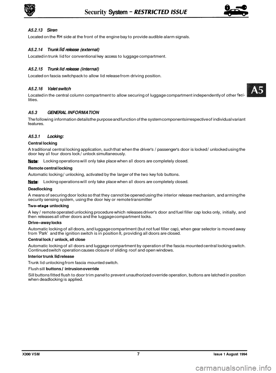
A5.3 GENERAL INFORMATION
The following information detailsthe purpose and function of the system components irrespective of individual variant
features.
A5.3.1 Locking:
Central locking
A traditional central locking application, such that when the driver's / passenger's door is locked / unlocked using the
door key all four doors lock / unlock simultaneously.
1ynfe: Locking operations will only take place when all doors are completely closed.
Remote central locking
Automatic locking / unlocking, activated by the larger of the two key fob buttons.
1ynfe: Locking operations will only take place when all doors are completely closed.
Deadlocking
A means of securing door locks so that they cannot be opened using the interior release mechanism, and arming the
security sensing system, using the door key or remote transmitter
Two-otage unlocking
A key / remote operated unlocking procedure which releases driver's door and fuel filler cap locks only, initially, and
then releases all other doors and the luggage compartment locks.
Drive-away locks
Automatic locking of all doors, and luggage compartment (but not fuel filler cap), when gear selector is moved away
from 'Park' and the ignition switch is in position II, providing all doors are closed.
Central lock / unlock, all close
Automatic locking of all doors and luggage compartment by operation of the fascia mounted central locking switch.
Continued switch operation causes closure of sliding roof and open windows.
Interior trunk lid release
Trunk lid unlocking from fascia mounted switch.
Flush sill buttons / intrusion override
Sill buttons fitted flush to door trim panel to prevent unauthorized override operation, buttons are latched in position
when deadlocking is applied.
Security System - RESTRKTED lSSUE
A5.2.13 Siren
Located on the RH side at the front of the engine bay to provide audible alarm signals.
A5.2.14 Trunk lid release (external)
Located in trunk lid for conventional key access to luggage compartment.
A5.2.15 Trunk lid release (internal)
Located on fascia switchpack to allow lid release from driving position.
A5.2.16 Valet switch
Located in the central column compartment to allow securing of luggage compartment independently of other faci-
X300 VSM 7 Issue 1 August 1994
Page 490 of 521
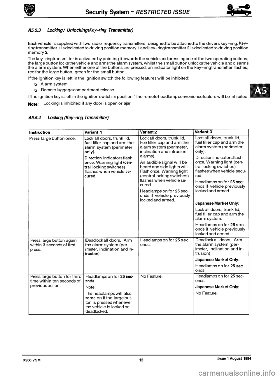
w:
A5.5.4 Locking (Key-ring Transmitter)
Locking is inhibited if any door is open or ajar.
nstruction
'ress large button once.
Press large button again
within
3 seconds of first
press.
Press large button for third
time within ten seconds of
previous action.
rlariant 1
-ock all doors, trunk lid, 'uel filler cap and arm the
darm system (perimeter
mly).
lirection indicators flash
mce. Warning light (cen-
:ral locking switches)
'lashes when vehicle se-
:ured.
Deadlock all doors, Arm
the alarm system (per
- imeter, inclination and in-
:rusion).
Variant 2
Security System - RESTRICTED ISSUE
A5.5.3
Each vehicle is supplied with two radio frequency transmitters, designed to be attached to the drivers key-ring. Key- ring transmitter 1 is dedicated to driving position memory 1 and key-ring transmitter 2 is dedicated to driving position
memory 2.
The key-ring transmitter is activated by pointing it towards the vehicle and pressing one of the two operating buttons;
the large button locks the vehicle and arms the alarm system, whilst the small button unlocks the vehicle and disarms
the alarm system. When either one of the buttons are pressed, an indicator light on the key-ring transmitter flashes;
red for the large button, green for the small button.
If the ignition key is left in the ignition switch the following features will be inhibited:
Locking / Unlocking (Key-ring Transmitter)
0 Alarm system
0 Remote luggage compartment release.
If the ignition key is left in the ignition switch in position 1 the remote headlamp convenience feature will be inhibited. ~~ ~
Headlamps on for 25 sec- mds.
Note:
The headlamps will also :ome on if the large but-
ton is pressed whenever
the vehicle is locked or
deadlocked. Lock
all doors,
trunk lid,
Fuel filler cap and arm the
alarm system (perimeter,
inclination and intrusion
alarms).
An audible signal will be
heard and side lights will
Flash once. Warning light
(central locking switches)
flashes when vehicle se
- cured.
Headlamps on for
25 sec- onds if vehicle previously
locked and armed.
Headlamps on for
25 sec
onds.
No Feature.
Variant 3
Lock all doors, trunk lid,
fuel filler cap and arm the
alarm system (perimeter
only).
Direction indicators flash
once. Warning light (cen
-
tral locking switches)
flashes when vehicle secu-
red.
Headlamps on for
25 sec- onds if vehicle previously
locked and armed.
Japanese Market Only:
Lock all doors, trunk lid,
fuel filler cap and arm the
alarm system.
Headlamps on for
25 sec
onds if vehicle previously
locked and armed.
Deadlock all doors, Arm
the alarm system (per
-
imeter, inclination and in- trusion).
Japanese Market Only:
Headlamps on for 25 sec- onds.
Headlamps on for
25 sec-
onds.
Japanese Market Only;
No Feature.
Issue 1 August 1994 X300 VSM 13
Page 491 of 521
Security System - RESTRlCTED /SUE 84
-
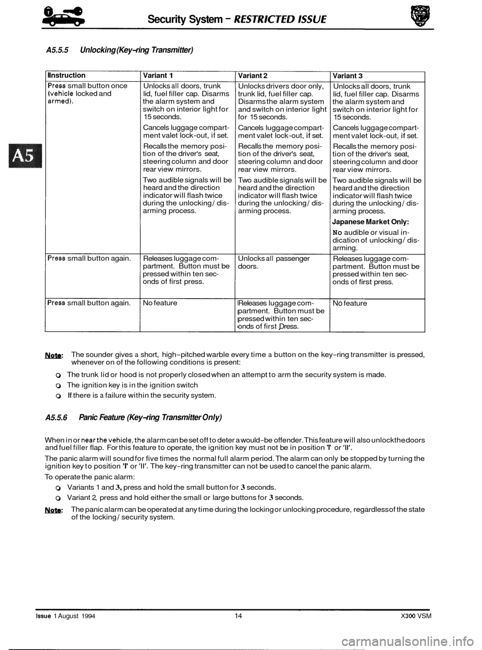
A5.5.5 Unlocking (Key-ring Transmitter)
Instruction
'ress small button once
Ivehicle locked and armed).
'ress small button again.
>ress small button again.
Variant 1
Unlocks all doors, trunk
lid, fuel filler cap. Disarms
the alarm system and
switch on interior light for
15 seconds.
Cancels luggage compart
-
ment valet lock-out, if set.
Recalls the memory posi
- tion of the driver's seat,
steering column and door
rear view mirrors.
Two audible signals will be
heard and the direction
indicator will flash twice
during the unlocking
/ dis- arming process.
Releases luggage com
- partment. Button must be
pressed within ten sec
- onds of first press.
No feature
Variant 2
Unlocks drivers door only,
trunk lid, fuel filler cap.
Disarms the alarm system
and switch on interior light
for 15 seconds.
Cancels luggage compart
-
ment valet lock-out, if set.
Recalls the memory posi
- tion of the driver's seat,
steering column and door
rear view mirrors.
Two audible signals will be
heard and the direction
indicator will flash twice
during the unlocking
/ dis-
arming process.
Unlocks
all passenger
doors.
Releases luggage com
-
partment. Button must be
pressed within ten sec
- onds of first Dress.
Variant 3
Unlocks all doors, trunk
lid, fuel filler cap. Disarms
the alarm system and
switch on interior light for
15 seconds.
Cancels luggage compart
-
ment valet lock-out, if set.
Recalls the memory posi
- tion of the driver's seat,
steering column and door
rear view mirrors.
Two audible signals will be
heard and the direction
indicator will flash twice
during the unlocking
/ dis-
arming process.
Japanese Market Only:
No audible or visual in-
dication of unlocking / dis- arming.
Releases luggage com
-
partment. Button must be
pressed within ten sec-
onds of first press.
No feature
M&:
o The trunk lid or hood is not properly closed when an attempt to arm the security system is made.
0 The ignition key is in the ignition switch
0 If there is a failure within the security system.
The
sounder gives
a short, high-pitched warble every time a button on the key-ring transmitter is pressed,
whenever on of the following conditions is present:
A5.5.6 Panic Feature (Key-ring Transmitter Only)
When in or nearthe vehicle,the alarm can be set off to deter a would-be offender. This feature will also unlockthe doors
and fuel filler flap. For this feature to operate, the ignition key must not be in position 'I' or '11'.
The panic alarm will sound for five times the normal full alarm period. The alarm can only be stopped by turning the
ignition key to position 'I' or '11'. The key-ring transmitter can not be used to cancel the panic alarm.
To operate the panic alarm:
0 Variants 1 and 3, press and hold the small button for 3 seconds.
o Variant 2, press and hold either the small or large buttons for 3 seconds.
MzW The panic alarm can be operated at any time during the locking or unlocking procedure, regardless of the state
of the locking / security system.
Issue 1 August 1994 14 X300 VSM
Page 495 of 521
Security System - RESTRICTED MU€ 84
-
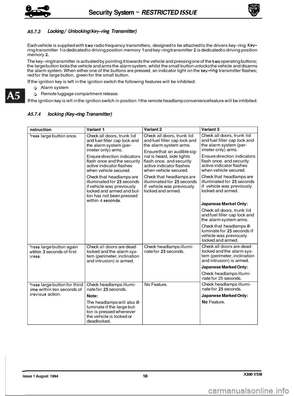
A5.7.3 Locking / Unlocking (Key-ring Transmitter)
Each vehicle is supplied with two radio frequency transmitters, designed to be attached to the drivers key-ring. Key- ring transmitter 1 is dedicated to driving position memory 1 and key-ring transmitter 2 is dedicated to driving position
memory 2.
The key-ring transmitter is activated by pointing it towards the vehicle and pressing one of the two operating buttons;
the large button locks the vehicle and arms the alarm system, whilst the small button unlocks the vehicle and disarms
the alarm system. When either one of the buttons are pressed, an indicator light on the
key-ring transmitter flashes;
red for the large button, green for the small button.
If the ignition key is left in the ignition switch the following features will be inhibited:
0 Alarm system
0 Remote luggage compartment release.
If the ignition key is left in the ignition switch in position 1 the remote headlamp convenience feature will be inhibited.
A5.7.4 locking (Key-ring Transmitter)
nstruction
'ress large button once.
'ress large button again
Nithin 3 seconds of first xess.
'ress large button for third
:ime within ten seconds of
3revious action.
Variant 1
Check all doors, trunk lid
and fuel filler cap lock and
the alarm system (per
- imeter only) arms.
Ensure direction indicators
flash once and the security
active indicator flashes
when vehicle secured.
Check that headlamps are
illuminated for
25 seconds
if vehicle was previously
locked and armed and but
-
ton has not been pressed
within
4 seconds.
Check all doors are dead-
locked and the alarm sys- tem (perimeter, inclination
and intrusion) is armed.
Check headlamps illumi
-
nate for 25 seconds.
Note:
The headlamps will also il- luminate if the large but-
ton is pressed whenever
the vehicle is locked
or
deadlocked.
Variant 2
Check all doors, trunk lid
and fuel filler cap lock and
the alarm system arms.
Ensure that an audible sig
-
nal is heard, side lights
flash once. and security
active indicator flashes
when vehicle secured.
Check that headlamps
are
illuminated for 25 seconds
if vehicle was previously
locked and armed.
Check headlamps illumi
-
nate for 25 seconds.
No Feature.
Variant 3
Check all doors, trunk lid
and fuel filler cap lock and
the alarm system (per
- imeter only) arms.
Ensure direction indicators
flash once. and security
active indicator flashes
when vehicle secured.
Check that headlamps are
illuminated for
25 seconds if vehicle was previously
locked and armed.
Japanese Market Only:
Check all doors, trunk lid
and fuel filler cap lock and
the alarm system arms.
Check that headlamps
il-
luminate for 25 seconds if
vehicle was previously
locked and armed.
Check all doors are dead
-
locked and the alarm sys- tem (perimeter, inclination
and intrusion) is armed.
Japanese Marked Only:
Check headlamps illumi-
nate for 25 seconds. __ Check headlamps illumi-
nate for 25 seconds.
Japanese Marked Only:
No Feature.
X300 VSM issue 1 August 1994 18
Page 497 of 521
Security System - RESTRICTED ISSUE
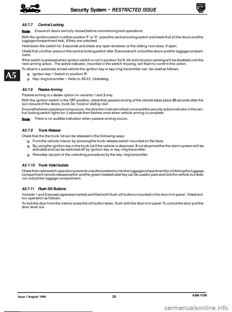
A5.7.7 Central Locking
W
With the ignition switch in either position 'I' or 'll', press the central locking switch and check that all the doors and the
luggage compartment lock, if they are unlocked.
Hold down the switch for
3 seconds and check any open windows or the sliding roof close, if open.
Check that
a further press on the central locking switch after 3 seconds will unlock the doors and the luggage compart- ment.
If the switch is pressed when ignition switch is not in position I or II, tilt and intrusion sensing will be disabled until the
next arming action. The active indicator, mounted in the switch housing, will flash to confirm this action.
To disarm
a passively armed vehicle the ignition key or key-ring transmitter can be used as follows:
Ensure
all doors
are fully closed before commencing lock operations.
0 Ignition key - Switch to position '11'.
0 Key-ring transmitter - Refer to A5.3.5 Unlocking.
A5.7.8 Passive Arming
Passive arming is a dealer option on variants 1 and 3 only.
With the ignition switch in the OFF position, check that passive arming of the vehicle takes place
30 seconds after the last closure of the doors, trunk lid, hood or sliding roof.
Ensurethat when passive arming occurs, the direction indicators flash once and the security active indicator in the cen
- tral locking switch lights for 2 seconds then flashes once when vehicle arming is complete.
W There is no audible indication when passive arming occurs.
A5.7.9 Trunk Release
Check that the the trunk lid can be released in the following ways:
0 From the vehicle interior by pressing the trunk release switch mounted on the facia.
0 By using the ignition key in the trunk lid if the vehicle is disarmed. If not disarmed the the alarm system will be
activated and can be switched off by ignition key or key-ring transmitter.
0 Remotely (as part of the unlocking procedure) by the key-ring transmitter.
A5.7.10 Trunk Valet Isolate
Check that valet switch operation prevents unauthorized entry into the luggagecompartment by inhibiting the luggage
compartment remote release switch and the green headed valet key can be used to park and lock the vehicle but does
not unlock the luggage compartment.
A5.7.11 Flush Sill Buttons
Variants 1 and 3 (except Japanese market) are fitted with flush sill buttons mounted in the door trim panel. Check but- ton operation as follows:
To lock the door from the interior press the sill button down, flush with the door trim panel. To unlock the door pull the
door lever out.
X300 VSM Issue 1 August 1994 20