check transmission fluid JAGUAR XJ6 1994 2.G Workshop Manual
[x] Cancel search | Manufacturer: JAGUAR, Model Year: 1994, Model line: XJ6, Model: JAGUAR XJ6 1994 2.GPages: 521, PDF Size: 17.35 MB
Page 128 of 521
Manual Transmission & Clutch (AJl6)
0
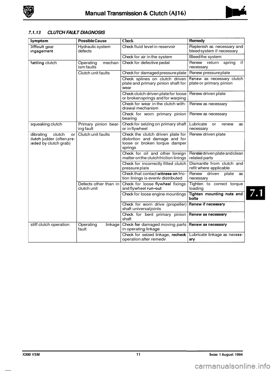
7.1.13 CLUTCH FAULT DIAGNOSIS
symptom
lifficult gear ?ngagement
3attling clutch
squeaking clutch
dibrating clutch or
:lutch judder (often pre- :eded by clutch grab)
stiff clutch operation
Possible Cause
Hydraulic system
defects
Operating mechan
- ism faults
Clutch unit faults
Primary pinion bear
-
ing fault
Clutch unit faults
Defects other than in
clutch unit
Operating linkage
fault
Check
Check fluid level in reservoir
Check for air in the system
Check for defective pedal
Check for damaged pressure plate
Check splines on clutch driven
plate and primary pinion shaft for
wear
Check clutch driven plate for loose
or broken springs and for warping
Check for wear in the clutch with
- drawal mechanism
Check for worn primary pinion
bearing
Check for seizing on primary shaft
or in flywheel
Check the clutch driven plate for
distortion and damage and for
loose or broken torque damper
springs
Check for oil and other foreign
matter on the clutch friction linings
Check for incorrectly fitted clutch
pressure
plate
Check that contact witness on fric-
tion linings is evenlv distributed -
Check for loose flvwheel fixings
and flywheel
run-out
Check for loose engine mountings
Check for worn drive (propeller)
shaft universal joints
Check for bent primary pinion
shaft
-
Check for damaged moving parts
in operating linkage
- -
Check for seized linkage, recheck
operation after remedv
Remedy
Replenish as necessary and
bleed system if necessary
Bleed the system
Renew return spring if
necessary
Renew pressure plate
Renew as necessary clutch
plate or primary pinion
Renew driven plate
Renew as necessary
Renew as necessary
Lubricate or renew as
necessary
Renew driven plate
Renew driven plate and clean
related parts
Dismantle from clutch and
refit where applicable
Renew driven plate as
necessary
Tighten to correct torque
loading
Lubricate linkage as
necess-
X300 VSM 11 Issue 1 August 1994
Page 143 of 521
bZF Automatic Transmission (AJ16) -
0
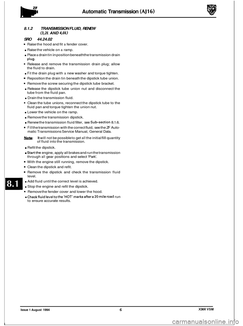
8.1.2 TRANSMISSION FLUID, RENEW
SRO 44.24.02
= Raise the hood and fit a fender cover.
. Raise the vehicle on a ramp.
. Place a drain tin in position beneath the transmission drain
Release and remove the transmission drain plug; allow
. Fit the drain plug with a new washer and torque tighten.
Reposition the drain tin beneath the dipstick tube union.
Remove the screw securing the dipstick tube bracket.
. Release the dipstick tube union nut and disconnect the
tube from the fluid pan.
. Drain the transmission fluid.
Clean the tube unions, reconnect the dipstick tube to the
. Lower the vehicle on the ramp.
. Remove the transmission dipstick.
. Renew the transmission fluid filter, see Subsection 8.1.6.
Fill the transmission with the correct fluid, see the ZF Auto-
Note: It will not be possible to get all the initial fill quantity
of fluid into the transmission.
. Refit the dipstick.
. Startthe engine, apply all brakes and run the transmission
With the engine still running, remove the dipstick.
Clean the dipstick and refit.
Remove the dipstick and check the transmission fluid
. Add fluid until the correct level is achieved.
. Stop the engine and refit the dipstick.
. Checkfluidleveltothe'HOT'marksaftera20mileroad run
(3,2L AND 4,OL)
Plug.
the fluid to drain.
fluid pan and torque tighten the union nut.
0
matic Transmissions Service Manual, General Data.
through
all gear positions and select 'Park'.
level. Remove the fender cover and lower the hood.
to ensure accurate results.
m
e
0
X300 VSM Issue 1 August 1994 6
Page 145 of 521
Automatic Transmission (AJ16)
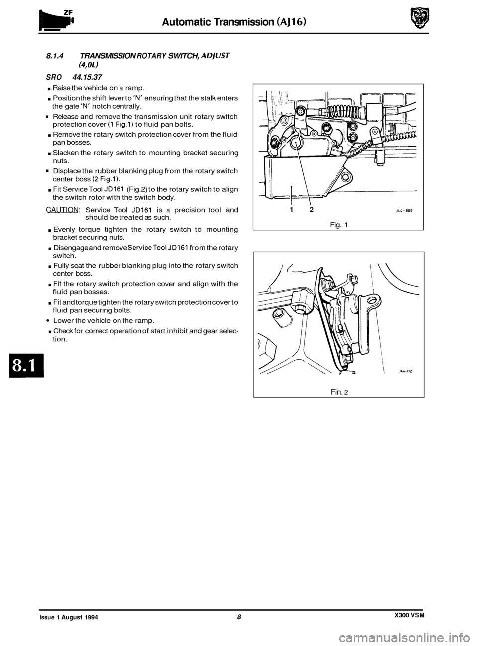
8.1.4 TRANSMISSION ROTARY SWITCH, ADjUST
SRO 44.15.37
. Raise the vehicle on a ramp.
. Position the shift lever to 'N' ensuring that the stalk enters
the gate
'N' notch centrally.
9 Release and remove the transmission unit rotary switch
protection cover
(1 Fig.1) to fluid pan bolts.
. Remove the rotary switch protection cover from the fluid
pan bosses.
. Slacken the rotary switch to mounting bracket securing
nuts.
Displace the rubber blanking plug from the rotary switch
center boss
(2 Fig.1).
. Fit Service Tool JD161 (Fig.2) to the rotary switch to align
the switch rotor with the switch body.
CAUTION: Service Tool JD161 is a precision tool and
. Evenly torque tighten the rotary switch to mounting
. Disengage and remove ServiceTool JD161 from the rotary
. Fully seat the rubber blanking plug into the rotary switch
. Fit the rotary switch protection cover and align with the
. Fit and torque tighten the rotary switch protection cover to
Lower the vehicle on the ramp.
. Check for correct operation of start inhibit and gear selec-
(4,011
should be treated as such.
bracket securing nuts.
switch.
center boss.
fluid pan bosses.
fluid pan securing bolts.
tion.
12 JL 4 - 689
Fig. 1
Fin. 2
X300 VSM Issue 1 August 1994 8
Page 152 of 521
Automatic Transmission (AJ16)
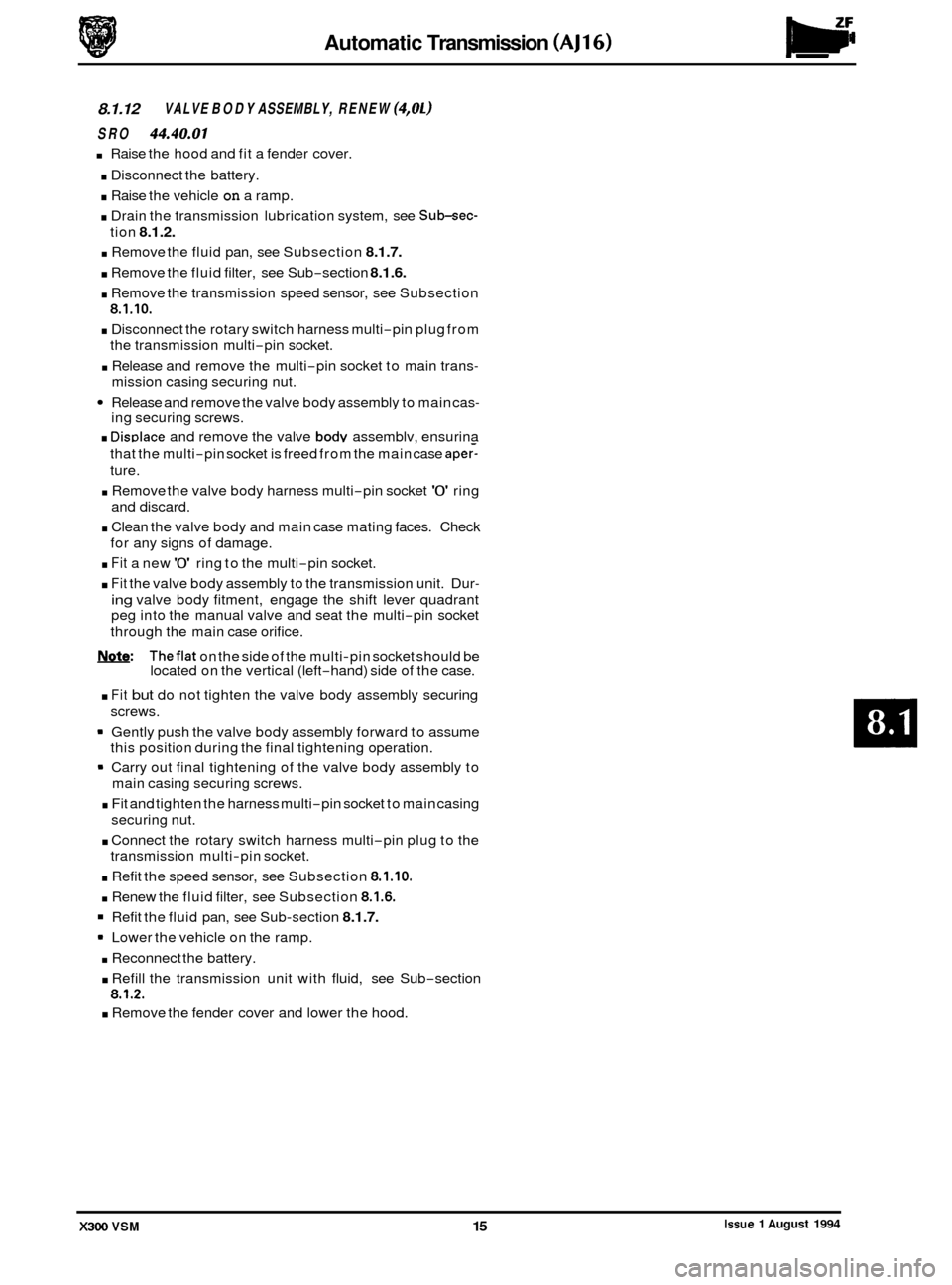
8.1.12 VALVE BODY ASSEMBLY, RENEW (4,Ol)
SRO 44.40.01
Raise the hood and fit a fender cover.
. Disconnect the battery.
. Raise the vehicle on a ramp.
. Drain the transmission lubrication system, see Sub-sec-
. Remove the fluid pan, see Subsection 8.1.7.
. Remove the fluid filter, see Sub-section 8.1.6.
. Remove the transmission speed sensor, see Subsection
8.1.10.
. Disconnect the rotary switch harness multi-pin plug from
the transmission multi
-pin socket.
. Release and remove the multi-pin socket to main trans-
mission casing securing nut.
Release and remove the valve body assembly to main cas-
ing securing screws.
. DisDlace and remove the valve body assemblv, ensurina
tion
8.1.2.
that
the multi-pin socket is freed from the main case apery
ture. - . Remove the valve body harness multi-pin socket '0' ring
. Clean the valve body and main case mating faces. Check
. Fit a new '0' ring to the multi-pin socket.
. Fit the valve body assembly to the transmission unit. Dur-
ing valve body fitment, engage the shift lever quadrant
peg into the manual valve and seat the multi
-pin socket
through the main case orifice.
m: Theflat on the side of the multi-pin socket should be
located on the vertical (left-hand) side of the case.
. Fit but do not tighten the valve body assembly securing
screws.
Gently push the valve body assembly forward to assume
this position during the final tightening operation.
Carry out final tightening of the valve body assembly to
main casing securing screws.
. Fit and tighten the harness multi-pin socket to main casing
. Connect the rotary switch harness multi-pin plug to the
. Refit the speed sensor, see Subsection 8.1.10.
. Renew the fluid filter, see Subsection 8.1.6.
Refit the fluid pan, see Sub-section 8.1.7.
* Lower the vehicle on the ramp.
. Reconnect the battery.
. Refill the transmission unit with fluid, see Sub-section
8.1.2.
. Remove the fender cover and lower the hood.
and discard.
for any signs of damage.
securing nut.
transmission multi
-pin socket.
Issue 1 August 1994 X300 VSM 15
Page 169 of 521
Automatic Transmission (V12 & AJ16 Supercharged) Powertrain
0
8.2.13 LUBRICATION SYSTEM, DRAIN AND REFILL
(4,OL SC AND 6,OL)
SRO 44.24.02
. Raise the vehicle on a ramp.
. Position a drain tin below the transmission unit.
. Release and remove the fluid pan drain plug.
. Allow the fluid to drain.
Clean the drain plug, including the magnet and the fluid
pan drain plug face.
. Fit and tighten the fluid pan drain plug.
. Remove the drain tin from below the transmission unit.
. Lower the vehicle on the ramp.
Open the hood and fit
a suitable fender cover.
Remove and wipe the dipstick.
. Fit a funnel to the dipstick tube.
. Initially fill the transmission with 4,5 liters of fluid.
. Remove the funnel.
. Open the front door.
. Check that the parking brake is applied.
. Start the engine.
Apply the footbrake.
Run the shift lever through all positions, finally returning
to the Park position.
. Release the footbrake.
. Insert the dipstick, then remove and inspect the level.
. Fit the funnel to the dipstick tube.
. Fill the transmission to the 'COLD' level mark on the dip-
stick with the correct fluid, see the Powertrain Automatic
Transmissions Service Manual, General Data.
CAUTION: On no account should the vehicle be driven un- less the fluid level is at the 'COLD' level and the
system primed.
0
Remove the funnel.
. Replace the dipstick.
. Switch the ignition OFF.
. Remove the fender cover and close the hood.
= Close the door.
J&&Q: 0 After road testing the vehicle, the fluid level on the
dipstick should be between the 'HOT' Min I Max
marks. Check the level with the transmission at nor-
mal operating temperature (90 to 100°C), with the
engine left running and the transmission in the Park
position.
m
0
Issue 1 August 1994 14 X300 VSM ~
__
Page 178 of 521
Pomrtrain Automatic Transmission (V12 & AJ16 Supercharged)
8.2.22 MANUAL DETENT SPRING, RENEW
SRO 44.26.10
9 Open the hood and fit a suitable fender cover.
. Raise the vehicle on a ramp.
. Drain the transmission lubrication system, see Sub-sec-
. Remove the fluid pan, see Subsection 8.2.14 (4,OL SC) or
. Remove the fluid filter, see Subsection 8.2.18.
. Select 'P (Park) and ensure that the pawl is engaged.
Release and remove the manual valve detent spring and
Remove the detent spring assembly and place aside.
. Clean the relevant parts.
Fit a new detent spring assembly to the valve body.
Fit but do not fully tighten the detent spring assembly to
the valve body securing bolts.
. Align the detent spring tocentralize the roller with the det- ent lever in the 'P' (Park) position.
. Check that in 'N' (Neutral), the shift lever is properly in
position. It is essential that the detent spring within the
transmission unit dictates to the shift lever and not the
other way around.
Finally tighten the detent spring assembly to valve body
securing bo
I ts .
(4,OL SC AND 6,011
tion 8.2.13.
Sub
-section 8.2.15 (6,OL).
roller assembly to valve body securing bolts.
. Refit the fluid filter, see Subsection 8.2.18.
Refit the fluid pan, see Subsection 8.2.14 (4,OL SC) or
. Lower the vehicle on the ramp.
. Refill the transmission unit with fluid, see Subsection 8.2.13.
. Remove the fender cover and close the hood.
Sub
-section
8.2.15 (6,OL).
X300 VSM 23 Issue 1 August 1994
Page 350 of 521
31
30
29
28 27
26
4 26 24 21 23 22 7 20 19 18 18 17 8
a
10
11
12
13
14
1s
1M-137
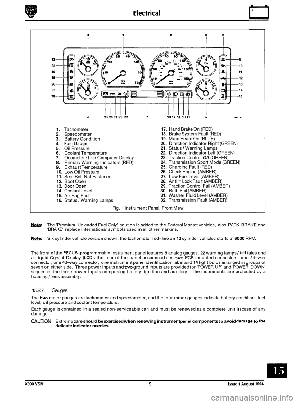
1. Tachometer 2. Speedometer
3. Battery Condition 4. FuelGauge 5. Oil Pressure 6. Coolant Temperature 7. Odometer /Trip Computer Display 8. Primary Warning Indicators (RED) 9. Exhaust Temperature 10. Low Oil Pressure 11. Seat Belt Not Fastened 12. Boot Open 13. DoorOpen 14. Coolant Level 15. Air Bag Fault 16. Status / Warning Lamps
17. Hand Brake On (RED) 18. Brake System Fault (RED)
19. Main Beam On (BLUE) 20. Direction Indicator Right (GREEN) 21. Status / Warning Lamps 22. Direction Indicator Left (GREEN) 23. Traction Control Off (GREEN) 24. Transmission Sport Mode (GREEN) 25. Charging Fault (RED) 26. Check Engine (AMBER)
27. Low Fuel Level (AMBER) 28. Anti - Lock Fault (AMBER) 29. Traction Control Fail (AMBER) 30. Bulb Fail (AMBER) 31. Washer Fluid Level (AMBER) 32. Transmission Fault (AMBER)
Fig.
1 Instrument Panel, Front Mew
w: The 'Premium Unleaded Fuel Only' caution is added to the Federal Market vehicles, also 'PARK BRAKE and
'BRAKE' replace international symbols used in all other markets.
m: Six cylinder vehicle version shown; the tachometer red-line on 12 cylinder vehicles starts at 6000 RPM.
The front of the
PECUSprogrammable instrument panel features 6 analog gauges, 22 warning lamps /tell tales and
a Liquid Crystal Display (LCD), the rear of the panel accommodates two PCB mounted connectors, one 24-way
connector, one 48-way connector, one instrument panel identification label and 14 light bulbs arranged in groups of
seven on either side. Three power inputs and two ground inputs are provided for 'POWER UP' and 'POWER DOWN'
sequence, the three power inputs comprising battery, ignition and auxiliary. The instruments are protected by a
housing
/ lens assembly.
15.2.7 Gauges
The two major gauges are tachometer and speedometer, and the four minor gauges indicate battery condition, fuel
level, oil pressure and coolant temperature.
Each gauge is contained
in a sealed non-serviceable can and must be renewed as a complete unit in case of any
damage.
CAUTION: Extreme care should be exercised when renewing instrument pand components to avoid damago to the delicate indicator needles.
X300 VSM 9 Issue 1 August 1994
Page 404 of 521
Routine
e
0
0
0
-
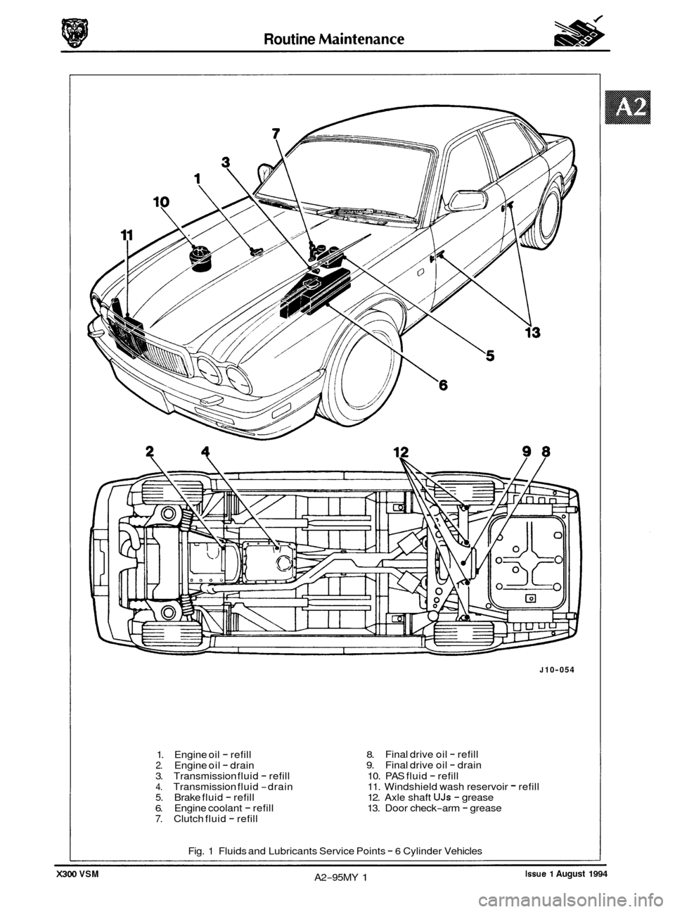
1. Engine oil - refill 2. Engine oil - drain
3. Transmission fluid - refill 4. Transmission fluid -drain 5. Brake fluid - refill 6. Engine coolant - refill 7. Clutch fluid - refill
J 10-054
8. 9.
10. PAS fluid
- refill
11. Windshield wash reservoir - refill
12. Axle shaft UJs - grease
13. Door check-arm - grease
Final
drive oil
- refill
Final drive oil - drain
Fig. 1 Fluids and Lubricants Service Points
- 6 Cylinder Vehicles
Issue 1 August 1994 A2-95MY 1 X300 VSM
Page 405 of 521
2 4 11 87
* * Rout ine Maintenance
- X300 VSM
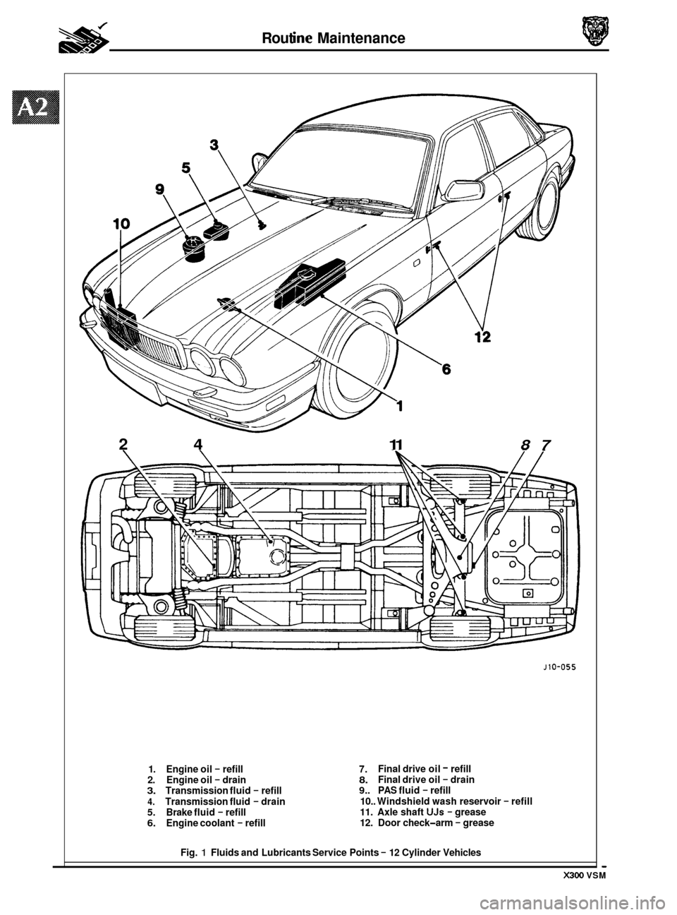
1. Engine oil - refill
2. Engine oil - drain 3. Transmission fluid - refill
4. Transmission fluid - drain 5. Brake fluid - refill 6. Engine coolant - refill
J10-055
7. 8. 9.. PAS fluid - refill
10.. Windshield wash reservoir
- refill 11. Axle shaft UJs - grease
12. Door check-arm - grease
Final drive
oil
- refill
Final drive oil - drain
Fig.
1 Fluids and Lubricants Service Points - 12 Cylinder Vehicles
Page 408 of 521
j
8
9
10
13 I
18
19
23
24
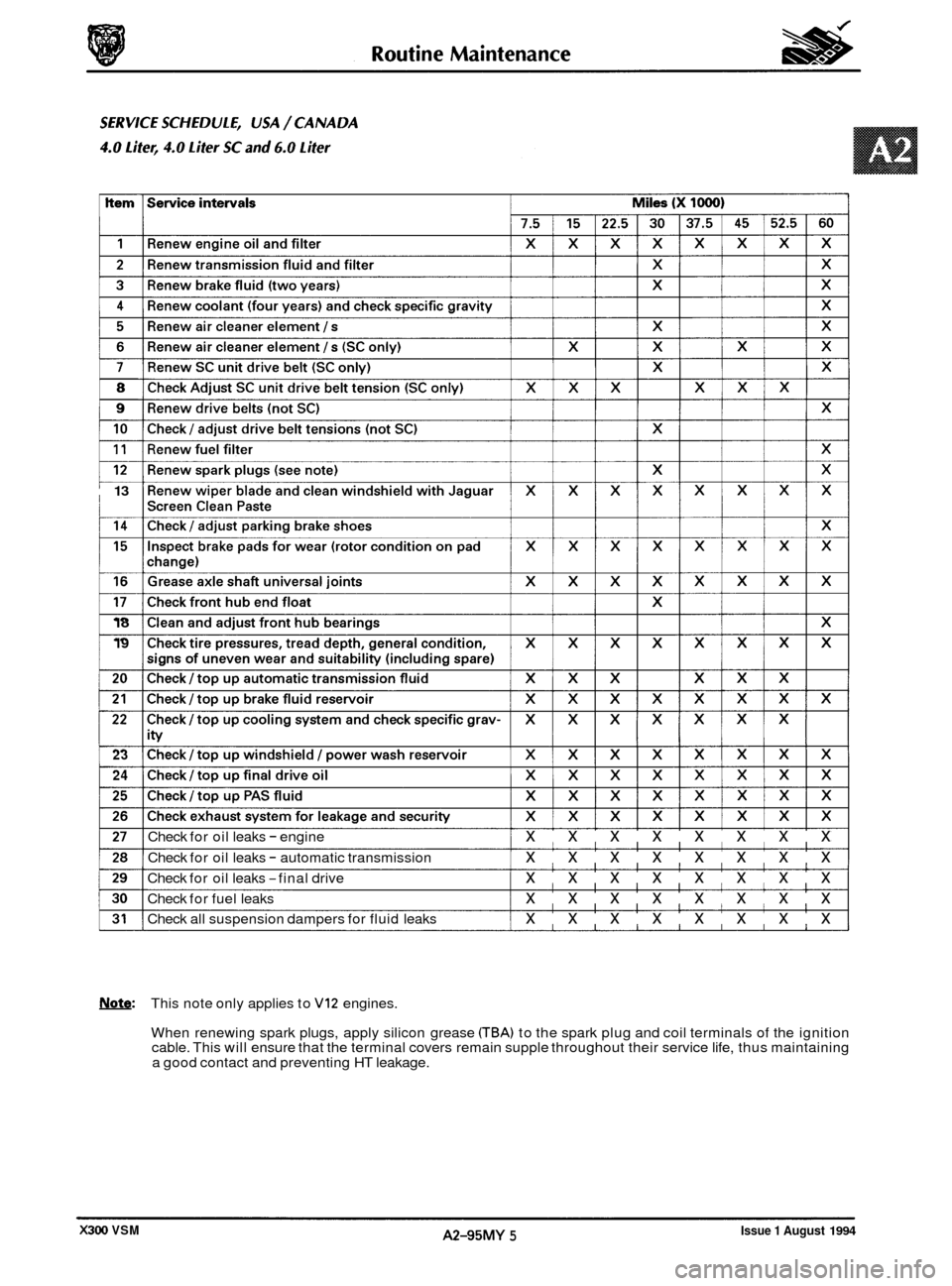
Check for oil leaks - engine xxxxxxxx
Check for oil leaks - automatic transmission xxxxxxxx
Check for oil leaks -final drive xxxxxxxx
Check for fuel leaks xxxxxxxx
Check all suspension dampers for fluid leaks xxxxxxxx
Note: This note only applies to VI2 engines.
When renewing spark plugs, apply silicon grease
CTBA) to the spark plug and coil terminals of the ignition
cable. This will ensure that the terminal covers remain supple throughout their service life, thus maintaining
a good contact and preventing HT leakage.
Issue 1 August 1994 A2-95MY 5 X300 VSM