clock JAGUAR XJ6 1994 2.G Workshop Manual
[x] Cancel search | Manufacturer: JAGUAR, Model Year: 1994, Model line: XJ6, Model: JAGUAR XJ6 1994 2.GPages: 521, PDF Size: 17.35 MB
Page 43 of 521
Engine (AJ16)
3.1.2 ENGlNE/ TRANSMlSSlON UN/& RENEW
SRO 12.41.02/20
The engine/transmission unit on the AJ 16 normally aspirated and supercharged engined vehicles are fitted ontothree
engine mounting/bracket assemblies. The two front engine mountings for the 3.2/4.0 liter normally aspirated and the
4.0 liter supercharged engined vehicles are identical. They are fitted to the front crossmember on either side of the
engine bay. Rubber to metal
engine/transmission rear mounts used for both engine types, are secured to a support
bracket which traverses the two body underframe longitudinal members. For access to remove the engine carry out the following procedures:
WARNING: WHEN WORKING WlTHlN THE ENGINE COMPARTMENT, KEEP CLEAR OF THE RADIATOR COOLING
FANS AS THEY COULD START WITHOUT WARNING EVEN IF THE ENGINE IS NOT RUNNING.
. Remove the hood, see SRO 76.16.01, section 13
. Remove the air cleaner assembly.
. Depressurize the fuel system, see SRO 19.50.02, section 5.1.
Disconnect the battery.
. In line with the relevant SRO's and sections, remove all appropriate obstructing parts, including their fixing and
. Disconnect all mechanical and isolate all electrical linkages leading to and from the engine.
. De-gas the airconditioning system, see section 14, Charge Recovery (System depressurization).
mounting
arrangements.
CAUTION : Do not vent refrigerant directly to the atmosphere and always use Jaguar approved recovery/recycle/re- charge equipment.
. Drain the engine oil, see 3.1.3 this section.
. Drain the coolant, see SRO 26.10.01, section 4.1.
WARNING: DO NOT REMOVE THE HEADER TANK PRESSURE CAP WHILE THE ENGINE IS HOT. IF THE CAP MUST
BE REMOVED, PROTECT THE HANDS AGAINST ESCAPING STEAM AND SLOWLY TURN THE CAP ANTI- CLOCKWISE UNTILTHE EXCESS PRESSURE CAN ESCAPE. LEAVETHE CAP IN THIS POSITION UNTIL ALL
STEAM AND PRESSURE HAS ESCAPED AND THEN REMOVE THE CAP COMPLETELY.
Before lifting the complete engine/transmission unit with an engine hoist from the engine bay, ensure that two engine
lifting brackets (tool 18G. 1465) are secured equally spaced to the inlet manifold studs. The engine lifting brackets
should be positioned towards the front and the rear of the assembly. Ensure the front of the vehicle is jacked
up secure- ly on stands when removing the assembly.
e
0
0
X300 VSM Issue 1 August 1994 2
Page 49 of 521
3.2.2 ENGINE - GEARBOX/ TRANSMISSION
ASSEMBLY, RENEW
SRO 12.37.01/90
The engine /transmission unit on the V12 6.0 liter model is mounted on three engine mounting / bracket assemblies
fitted to the front crossmember on either side of the engine bay. The engine/ transmission rear mount is a mounting
bracket and spring assembly fitted and secured to body underframe longitudinal members. For access to remove the
engine carry
out the following procedures:
WARNING: WHEN WORKING WITHIN THE ENGINE COMPARTMENT, KEEP CLEAR OF THE RADIATOR COOLING
FANS AS THEY COULD START WITHOUT WARNING, EVEN IF THE ENGINE IS NOT RUNNING.
. Remove the hood, see SRO 76.16.01, section 13.
. Remove the two air cleaner assemblies, see SRO’s 19.10.01 & 19.10.02.
. Remove the engine cover, see SRO 12.29.93 (V12 Engine Service Manual).
Depressurize the fuel system, see SRO 19.50.02, section 5.1.
In line with the relevant SRO’s and sections, remove all appropriate obstructing parts, including their fixing and
. Disconnect all mechanical and isolate all electrical linkages leading to and from the engine.
. De-gas the air conditioning system, see section 14, Charge Recovery (System depressurization).
Disconnect
the battery.
mounting arrangements.
CAUTION: Do
not vent refrigerant directly to the atmosphere and always use Jaguar approved recovery/recycle/ra charge equipment.
Drain the engine oil, see 3.2.3 this section.
Drain the coolant, see SRO 26.10.01, section 4.1.
WARNING: DO NOT REMOVE THE HEADER TANK PRESSURE CAP WHILE THE ENGINE IS HOT. IF THE CAP MUST
BE REMOVED, PROTECT THE HANDS AGAINST ESCAPING STEAM AND SLOWLY TURN THE CAP ANTI- CLOCKWISE UNTIL THE EXCESS PRESSURE CAN ESCAPE. LEAVE THE CAP IN THIS POSITION UNTIL ALL
STEAM AND PRESSURE HAS ESCAPED AND THEN REMOVE THE CAP COMPLETELY.
Before
lifting the complete engine/transmission unit with an engine hoist from the engine bay, ensure that two engine
lifting brackets (tool 18G. 1465) are secured equallyspaced to the inlet manifold studs. The four engine lifting brackets
should be positioned towards the front and the rear of the assembly. Ensure the front of thevehicle is jacked
up secure- ly on stands when removing the assembly.
X300 VSM Issue 1 August 1994 2
Page 58 of 521
area washed to remove all traces of coolant.
CAUTION: To prevent the possibility of damage to the heater circuit pump and supercharger pump (where fitted),
the pumps should be electrically isolated if the ignition has to be turned ON while the cooling system is
drained.
WARNING: DO NOT REMOVE THE HEADER TANK PRESSURE CAP WHILE THE ENGINE IS HOT. IF THE CAP MUST
BE REMOVED, PROTECT THE HANDS AGAINST ESCAPING STEAM AND SLOWLY TURN THE CAP ANTI
- CLOCKWISE UNTIL THE EXCESS PRESSURE CAN ESCAPE. LEAVE THE CAP IN THIS POSITION UNTIL
ALL THE STEAM AND PRESSURE HAS ESCAPED AND THEN REMOVE THE CAP COMPLETELY.
WARNING: WHEN DRAINING THE COOLANT WITH THE ENGINE HOT, PROTECT THE HANDS AGAINST CONTACT
WITH HOT COOLANT.
WARNING: WHEN WORKING WITHIN THE ENGINE COMPARTMENT, KEEP CLEAR OF THE RADIATOR COOLING
FANS. THE FANS COULD START WITHOUT WARNING EVEN IF THE ENGINE IS NOT RUNNING.
4.1.3.2 Working Practices
Whenfilling thesystem with coolant,ensurethatthevehicle isstanding on a level surfaceandthatthecoolant is poured
in slowly so that airlocks are not introduced into the system. Airlocks can seriously affect the operation of the climate
control system and can cause damage to the heater circuit pump (and supercharger circuit pump if fitted).
Cooling System (AJ16)
4.1.3 SERVICE PROCEDURES
4.1.3.1 Safety Precautions
The anti-freeze specified in Appendix AI must be used wherever possible. It is designed to afford the maximum cor- rosion protection to all metals found in the engine cooling system, as well as having the frost protection properties
necessary during the winter months.
Should
it not be available, then anti-freeze conforming to Ford Motor Company specification ESLbM97B49-A may be
used. To provide optimum temperature and corrosion protection, the specified anti-freeze concentration must always
be used.
Once coolant has been drained from the system,
it must be discarded and not reused. Anti-freeze is harmful to the
environment. Used coolant must be disposed of safely and never poured down a drain connected to the public sewer.
CAUTION: Never fill or topup the system with water only.
CAUTION : Anti-freeze is harmful to paintwork. Coolant spillages must be wiped up immediately and the affected
Hose clips should always be positioned so that there is proper access for tightening and that the clip does not foul or
interfere with the operation of any components.
Drive belts must always be tensioned to the specified value and the tension checked
at the correct point on the belt.
This information is given in Subsection IV in the preliminary pages.
0
When tightening components, the torque figures given in Sukection II in the preliminary pages should always be
used for the fastenings listed.
4.1.3.3 Coolant Change
The coolant must be changed at intervals of four years. The system should be drained from the radiator drain plug,
flushed and filled with fresh coolant. Flushing should be carried out thoroughly to remove all the old coolant from the
engineand heater matrix. (The heatervalve isopen withthe ignition OFF). AfterfiIling,checkthecoolant concentration
with a hydrometer. For the specified anti-freeze and coolant concentration, see Appendix AI.
X300 VSM 3 Issue 1 August 1994
Page 59 of 521
€3 Cooling System (AJ16)
4.1.4 DRAIN AND FILL PROCEDURES
4.1.4.1 Radiator, Drain
. Place a drain tray in position underthe radiator drain plug
. Remove the header tank pressure cap. Release the captive
Tighten the radiator drain plug.
CAUTION: This procedure does not drain the heater circuit.
(Fig. 1).
radiator drain plug and drain the coolant.
4.1.4.2 Engh-, Drain
m:
. Drain the radiator. (See the procedure above).
. Place a drain tray under the cylinder block drain plug (Fig.
Remove the block drain plug and drain the coolant.
. Fit the block drain plug.
This procedure
should only be necessary when the
engine is being dismantled.
2).
Fig. 1
Fia. 2
WAm. DO NOT REMOVE THE HEADER TANK PRESSURE CAP WHILE THE ENGINE IS HOT. IF THE CAP MUST
BE REMOVED, PROTECT THE HANDS AGAINST ESCAPING STEAM AND SLOWLY TURN THE CAP ANTI- CLOCKWISE UNTIL THE EXCESS PRESSURE CAN ESCAPE. LEAVE THE CAP IN THIS POSITION UNTIL ALL THE STEAM AND PRESSURE HAS ESCAPED AND THEN REMOVE THE CAP COMPLETELY.
WARNING: WHEN DRAINING THE COOLANT WITH THE ENGINE HOT, PROTECT THE HANDS AGAINST CONTACT
WITH HOT COOLANT.
4.1.4.3 Radiator, Fill
. Add coolant until the level in the header tank is steady at MAX. (Do not fit the header tank cap).
. Switch on the ignition. (The climate control system must be OFF).
Start the engine and wait until the cooling fans operate for the second time. (The engine speed may be raised to
While the cooling fans are operating, raise the engine speed to 1500 RPM for one minute. Return to idle speed.
. Switch off the ignition and wait for one minute.
Check that the coolant level in the header tank is between MAX and 10 mm above MAX. Add coolant as necessary.
Fit the header tank cap.
reduce
the warm up time).
Issue 1 August 1994 4 X300 VSM
Page 68 of 521
WARNING: DO NOT REMOVE THE HEADER TANK PRESSURE CAP WHILE THE ENGINE IS HOT. IF THE CAP MUST
BE REMOVED, PROTECT THE HANDS AGAINST ESCAPING STEAM AND SLOWLY TURN THE CAP ANTI- CLOCKWISE UNTIL THE EXCESS PRESSURE CAN ESCAPE. LEAVE THE CAP IN THIS POSITION UNTIL
ALL THE STEAM AND PRESSURE HAS ESCAPED AND THEN REMOVE THE CAP COMPLETELY.
WARNING: WHEN DRAINING THE COOLANT WITH THE ENGINE HOT, PROTECT THE HANDS AGAINST CONTACT
WITH HOT COOLANT.
WARNING
: WHEN WORKING WITHIN THE ENGINE COMPARTMENT, KEEP CLEAR OF THE ENGINE DRIVEN RADI- ATOR COOLING FAN WHEN THE ENGINE IS RUNNING.
4.2.3.2 Working Practices
Whenfilling thesystem with coolant,ensurethatthevehicle isstanding on a level surfaceand thatthecoolant is poured
in slowly so that airlocks are not introduced into the system. Airlocks can seriously affect the operation of the climate
control system and can cause damage to the heater circuit pump.
Hose clips should always be positioned
so that there is proper access for tightening and that the clip does not foul or
interfere with the operation of any components.
4.2.3 SERVICE PROCEDURES
4.2.3.1 Safety Precautions
The anti-freeze specified in Appendix A1 must be used wherever possible. It is designed to afford the maximum cor- rosion protection to all metals found in the engine cooling system, as well as having the frost protection properties
necessary during the winter months. Should it not be available, then anti-freeze conforming to Ford Motor Company
specification
ESBM97B49-A may be used. To provide optimum temperature and corrosion protection, the specified
anti-freeze concentration must always be used. Once coolant has been drained from the system, it must be discarded
and not reused. Anti-freeze is harmful to the environment. Always dispose of used coolant safely and never pour it down a drain connected to the public sewer.
CAUTION: Never fill or topup the system with water only.
CAUTION
: Anti-freeze is harmful to paintwork. Coolant spillages must be wiped up immediately and the affected
area washed to remove all traces of coolant.
CAUTION: To prevent the possibility of damage to the heater circuit
pump, the pump should be electrically isolated if the ignition has to be turned ON while the cooling system is drained.
The drive belt must always be tensioned to the specified value and the tension checked at the correct point on the belt.
This information is given in Sub-section IV in the preliminary pages.
When tightening components, the torque figures given in Sub
-section II in the preliminary pages should always be
used for the fastenings listed.
When fitting a replacement thermostat, ensure that the jiggle-pin is to the top of the thermostat housing.
4.2.3.3 Coolant Change
The coolant must be changed at intervals of four years. The system should be drained from the radiator drain plug,
flushed and filled with fresh coolant. Flushing should be carried out thoroughly to remove all the old coolant from the
engine and heater matrix. (The heatervalve isopen with the ignition OFF). AfterfilIing,checkthecoolant concentration
with a hydrometer. For specified anti-freeze and coolant concentration, see in Appendix Al.
X300 VSM 3 Issue 1 August 1994
Page 69 of 521
€3 Cooling System (V12)
4.2.4 DRAIN AND FILL PROCEDURES
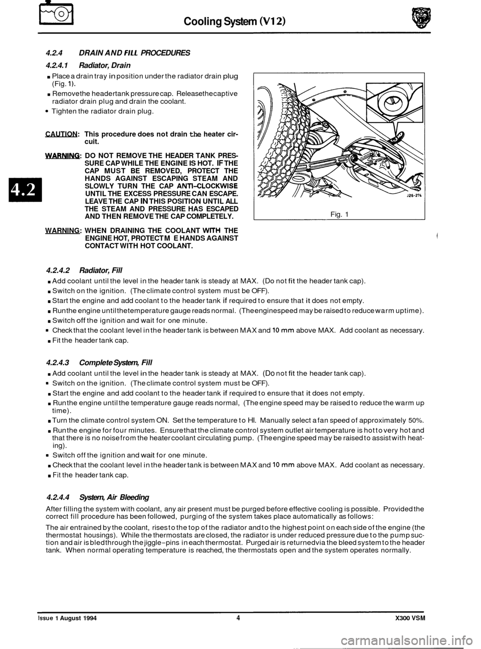
4.2.4.1 Radiator, Drain
. Place a drain tray in position under the radiator drain plug
. Remove the headertank pressure cap. Release thecaptive
Tighten the radiator drain plug.
(Fig.
1).
radiator drain
plug and drain the coolant.
CAUTION: This procedure does not drain the heater cir- cuit.
m: DO NOT REMOVE THE HEADER TANK PRES- SURE CAP WHILE THE ENGINE IS HOT. IF THE
CAP MUST BE REMOVED, PROTECT THE
HANDS AGAINST ESCAPING STEAM AND
SLOWLY TURN THE CAP
ANTI-CLOCKWISE UNTIL THE EXCESS PRESSURE CAN ESCAPE.
LEAVE THE CAP IN THIS POSITION UNTIL ALL
THE STEAM AND PRESSURE HAS ESCAPED
AND THEN REMOVE THE CAP COMPLETELY.
WARNING: WHEN DRAINING THE COOLANT
WITH THE
ENGINE HOT, PROTECT ME HANDS AGAINST
CONTACT WITH HOT COOLANT.
Fig. 1
4.2.4.2 Radiator, Fill
. Add coolant until the level in the header tank is steady at MAX. (Do not fit the header tank cap).
. Switch on the ignition. (The climate control system must be OFF).
. Start the engine and add coolant to the header tank if required to ensure that it does not empty.
. Run the engine until thetemperature gauge reads normal. (The enginespeed may be raised to reduce warm uptime).
. Switch off the ignition and wait for one minute.
Check that the coolant level in the header tank is between MAX and
10 mm above MAX. Add coolant as necessary.
. Fit the header tank cap.
4.2.4.3 Complete System, Fill
. Add coolant until the level in the header tank is steady at MAX. (Do not fit the header tank cap).
= Switch on the ignition. (The climate control system must be OFF).
. Start the engine and add coolant to the header tank if required to ensure that it does not empty.
. Run the engine until the temperature gauge reads normal, (The engine speed may be raised to reduce the warm up
. Turn the climate control system ON. Set the temperature to HI. Manually select a fan speed of approximately 50%.
. Run the engine for four minutes. Ensure that the climate control system outlet air temperature is hot to very hot and
that there is no noise from the heater coolant circulating pump. (The engine speed may be raised to assist with heat- ing).
time).
8 Switch
off the ignition and wait for one minute.
. Check that the coolant level in the header tank is between MAX and 10 mm above MAX. Add coolant as necessary.
. Fit the header tank cap.
4.2.4.4 System, Air Bleeding
After filling the system with coolant, any air present must be purged before effective cooling is possible. Provided the
correct fill procedure has been followed, purging of the system takes place automatically as follows:
The air entrained by the coolant, rises to the top of the radiator and to the highest point on each side of the engine (the
thermostat housings). While the thermostats are closed, the radiator is under reduced pressure due to the pump suc
- tion and air is bled through the jiggle-pins in each thermostat. Purged air is returnedvia the bleed system to the header
tank. When normal operating temperature is reached, the thermostats open and the system operates normally. ~~
Issue 1 August 1994 4 X300 VSM
Page 202 of 521
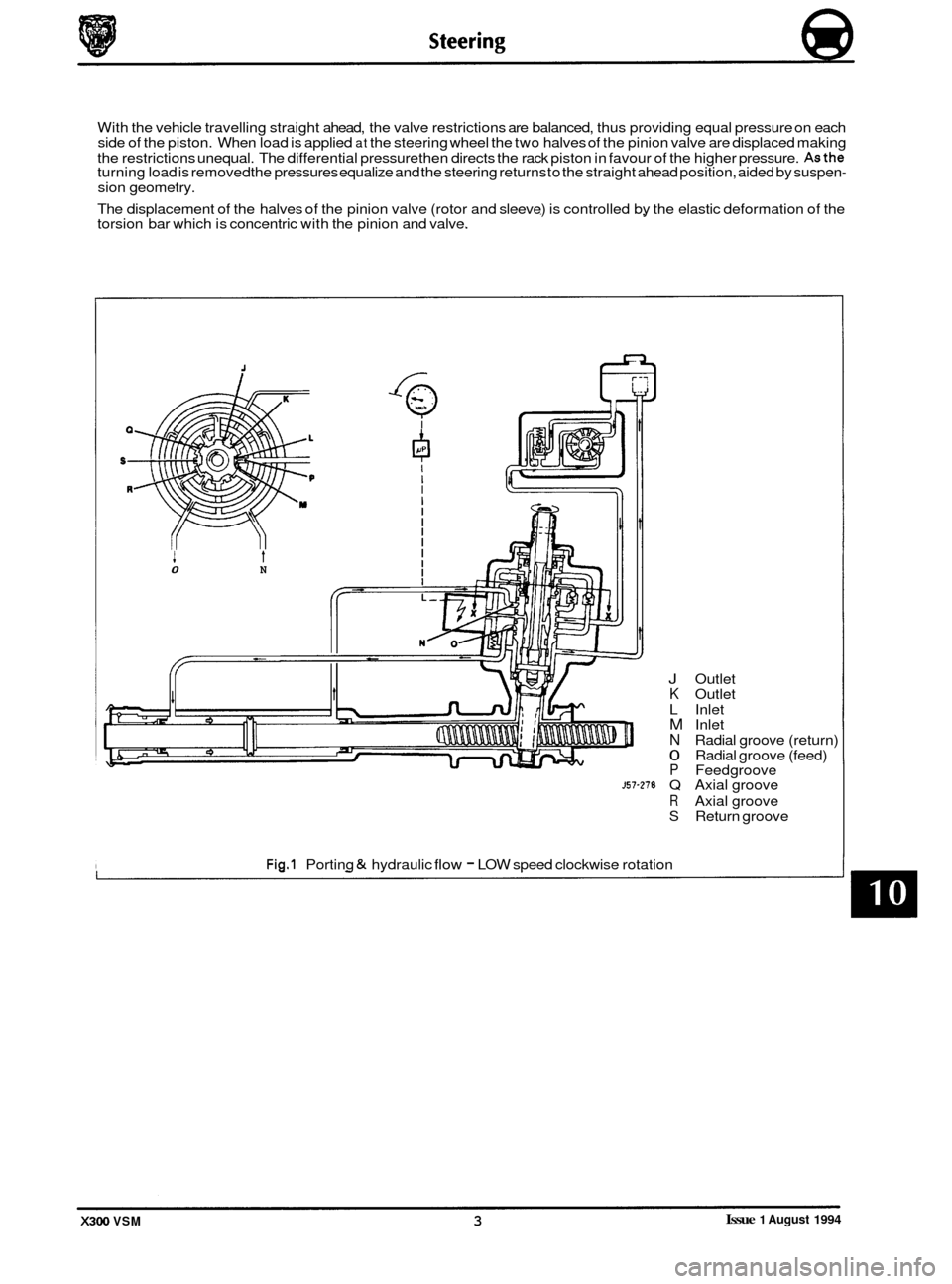
With the vehicle travelling straight ahead, the valve restrictions are balanced, thus providing equal pressure on each
side of the piston. When load is applied at the steering wheel the two halves of the pinion valve are displaced making
the restrictions unequal. The differential pressure then directs the rack piston in favour of the higher pressure.
Asthe turning load is removed the pressures equalize and the steering returns to the straight ahead position, aided by suspen-
sion geometry.
The displacement
of the halves of the pinion valve (rotor and sleeve) is controlled by the elastic deformation of the
torsion bar which is concentric with the pinion and valve.
0 N
J Outlet K Outlet
L Inlet
M Inlet
N Radial groove (return)
0 Radial groove (feed) P Feedgroove ~57-278 Q Axial groove
R Axial groove S Return groove
Fig.1 Porting & hydraulic flow - LOW speed clockwise rotation
Issue 1 August 1994 X300 VSM 3
Page 203 of 521
@ Steering
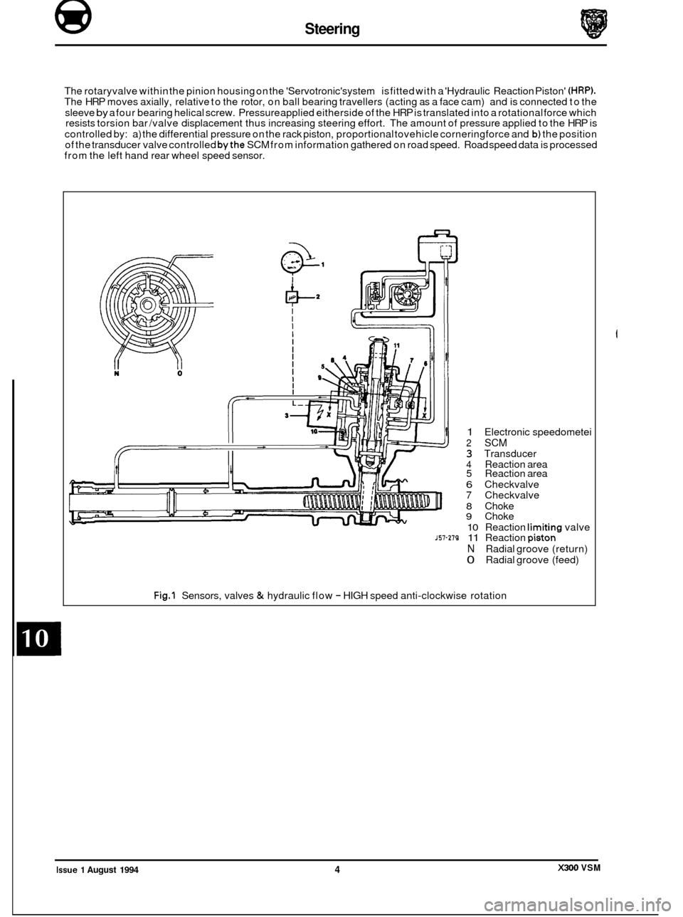
The rotaryvalve within the pinion housing on the 'Servotronic'system is fitted with a 'Hydraulic Reaction Piston' (HRP). The HRP moves axially, relative to the rotor, on ball bearing travellers (acting as a face cam) and is connected to the
sleeve
by a four bearing helical screw. Pressure applied eitherside of the HRP is translated into a rotational force which
resists torsion bar /valve displacement thus increasing steering effort. The amount of pressure applied to the HRP is
controlled by: a) the differential pressure on the rack piston, proportional tovehicle corneringforce and
b) the position
of the transducer valve controlled bythe SCM from information gathered on road speed. Road speed data is processed
from the left hand rear wheel speed sensor.
1 Electronic speedometei
2 SCM 3 Transducer 4 Reaction area 5 Reaction area
6 Checkvalve 7 Checkvalve
8 Choke 9 Choke
10 Reaction limitina valve 157-279 11 Reaction piston-
N Radial groove (return)
0 Radial groove (feed)
Fig.1 Sensors, valves & hydraulic flow - HIGH speed anti-clockwise rotation
X300 VSM Issue 1 August 1994 4
Page 271 of 521
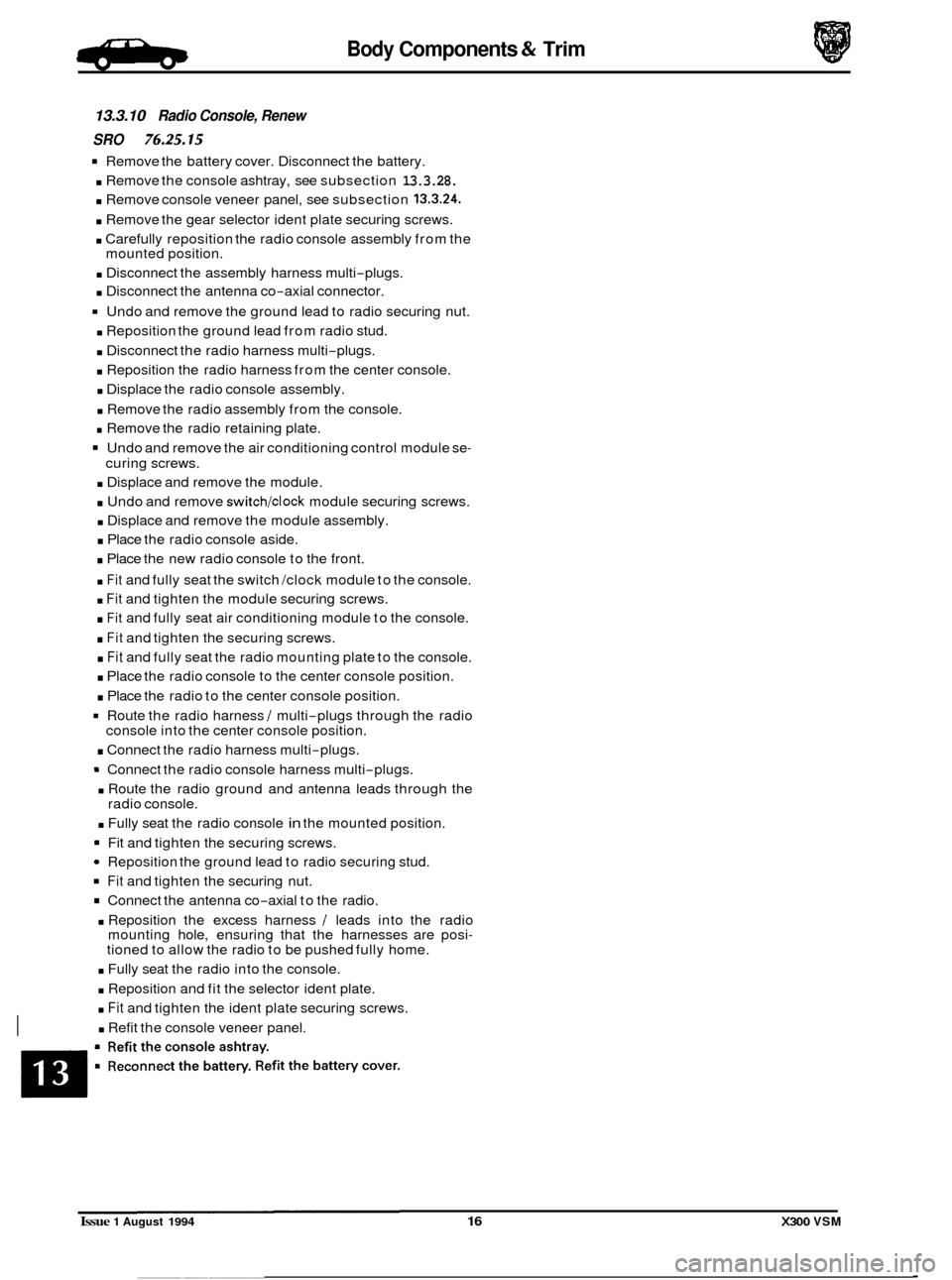
Body Components & Trim e
Remove the battery cover. Disconnect the battery.
. Remove the console ashtray, see subsection 13.3.28.
. Remove console veneer panel, see subsection 13.3.24.
. Remove the gear selector ident plate securing screws.
. Carefully reposition the radio console assembly from the
mounted position.
. Disconnect the assembly harness multi-plugs.
. Disconnect the antenna co-axial connector.
Undo and remove the ground lead to radio securing nut.
. Reposition the ground lead from radio stud.
. Disconnect the radio harness multi-plugs.
. Reposition the radio harness from the center console.
. Displace the radio console assembly.
. Remove the radio assembly from the console.
. Remove the radio retaining plate.
Undo and remove the air conditioning control module se
-
curing screws.
. Displace and remove the module.
. Undo and remove switch/clock module securing screws.
. Displace and remove the module assembly.
. Place the radio console aside.
. Place the new radio console to the front.
. Fit and fully seat the switch /clock module to the console.
. Fit and tighten the module securing screws.
. Fit and fully seat air conditioning module to the console.
. Fit and tighten the securing screws.
. Fit and fully seat the radio mounting plate to the console.
. Place the radio console to the center console position.
. Place the radio to the center console position.
* Route the radio harness / multi-plugs through the radio
. Connect the radio harness multi-plugs.
8 Connect the radio console harness multi-plugs.
. Route the radio ground and antenna leads through the
. Fully seat the radio console in the mounted position.
Reposition the ground lead to radio securing stud.
Fit and tighten the securing nut.
Connect the antenna co-axial to the radio.
. Reposition the excess harness / leads into the radio
mounting hole, ensuring that the harnesses are posi- tioned to allow the radio to be pushed fully home.
console
into the center console position.
radio console.
Fit and tighten the securing screws.
. Fully seat the radio into the console.
. Reposition and fit the selector ident plate.
. Fit and tighten the ident plate securing screws.
. Refit the console veneer panel. I
13.3.10 Radio Console, Renew
SRO
76.25.15
Issue 1 August 1994 16 X300 VSM
Page 299 of 521
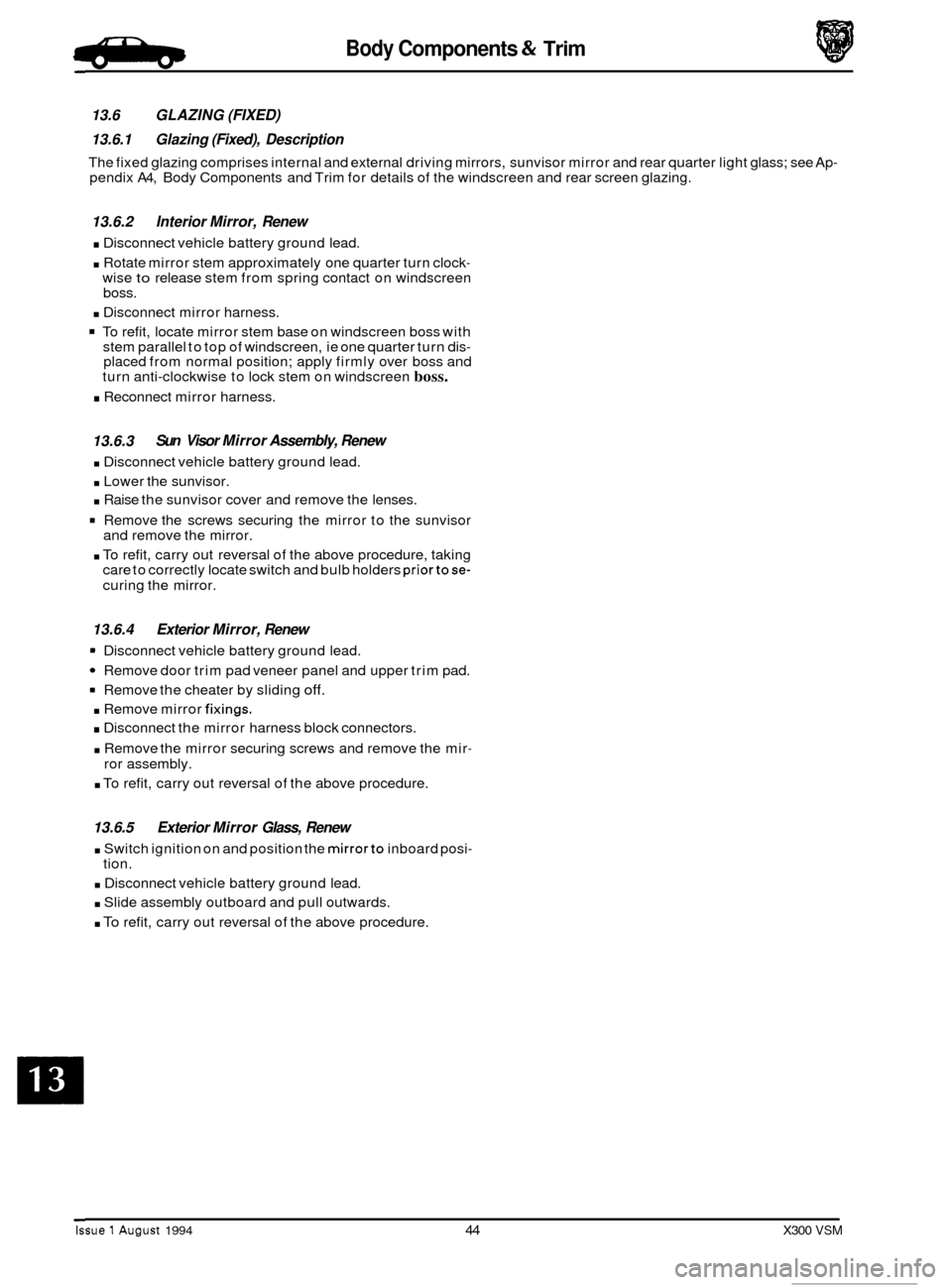
Body Components & Trim #ib
13.6 GLAZING (FIXED)
13.6.1 Glazing (Fixed), Description
The fixed glazing comprises internal and external driving mirrors, sunvisor mirror and rear quarter light glass; see Ap- pendix A4, Body Components and Trim for details of the windscreen and rear screen glazing.
13.6.2 Interior Mirror, Renew
. Disconnect vehicle battery ground lead.
. Rotate mirror stem approximately one quarter turn clock- wise to release stem from spring contact on windscreen
boss.
. Disconnect mirror harness.
To refit, locate mirror stem base on windscreen boss with
stem parallel to top of windscreen, ie one quarter turn dis- placed from normal position; apply firmly over boss and
turn anti-clockwise to lock stem on windscreen boss.
. Reconnect mirror harness.
13.6.3
. Disconnect vehicle battery ground lead.
. Lower the sunvisor.
. Raise the sunvisor cover and remove the lenses.
Remove the screws securing the mirror to the sunvisor
and remove the mirror.
. To refit, carry out reversal of the above procedure, taking
care to correctly locate switch and bulb holders priortose-
curing the mirror.
Sun Visor Mirror Assembly, Renew
13.6.4 Exterior Mirror, Renew
= Disconnect vehicle battery ground lead.
Remove door trim pad veneer panel and upper trim pad.
9 Remove the cheater by sliding off.
. Remove mirror fixings.
. Disconnect the mirror harness block connectors.
. Remove the mirror securing screws and remove the mir-
ror assembly.
. To refit, carry out reversal of the above procedure.
13.6.5 Exterior Mirror Glass, Renew
. Switch ignition on and position the mirrorto inboard posi-
. Disconnect vehicle battery ground lead.
. Slide assembly outboard and pull outwards.
. To refit, carry out reversal of the above procedure.
tion.
Issue 1 August 1994 44 X300 VSM