window JAGUAR XJ6 1994 2.G Workshop Manual
[x] Cancel search | Manufacturer: JAGUAR, Model Year: 1994, Model line: XJ6, Model: JAGUAR XJ6 1994 2.GPages: 521, PDF Size: 17.35 MB
Page 250 of 521

Body Components & Trim .
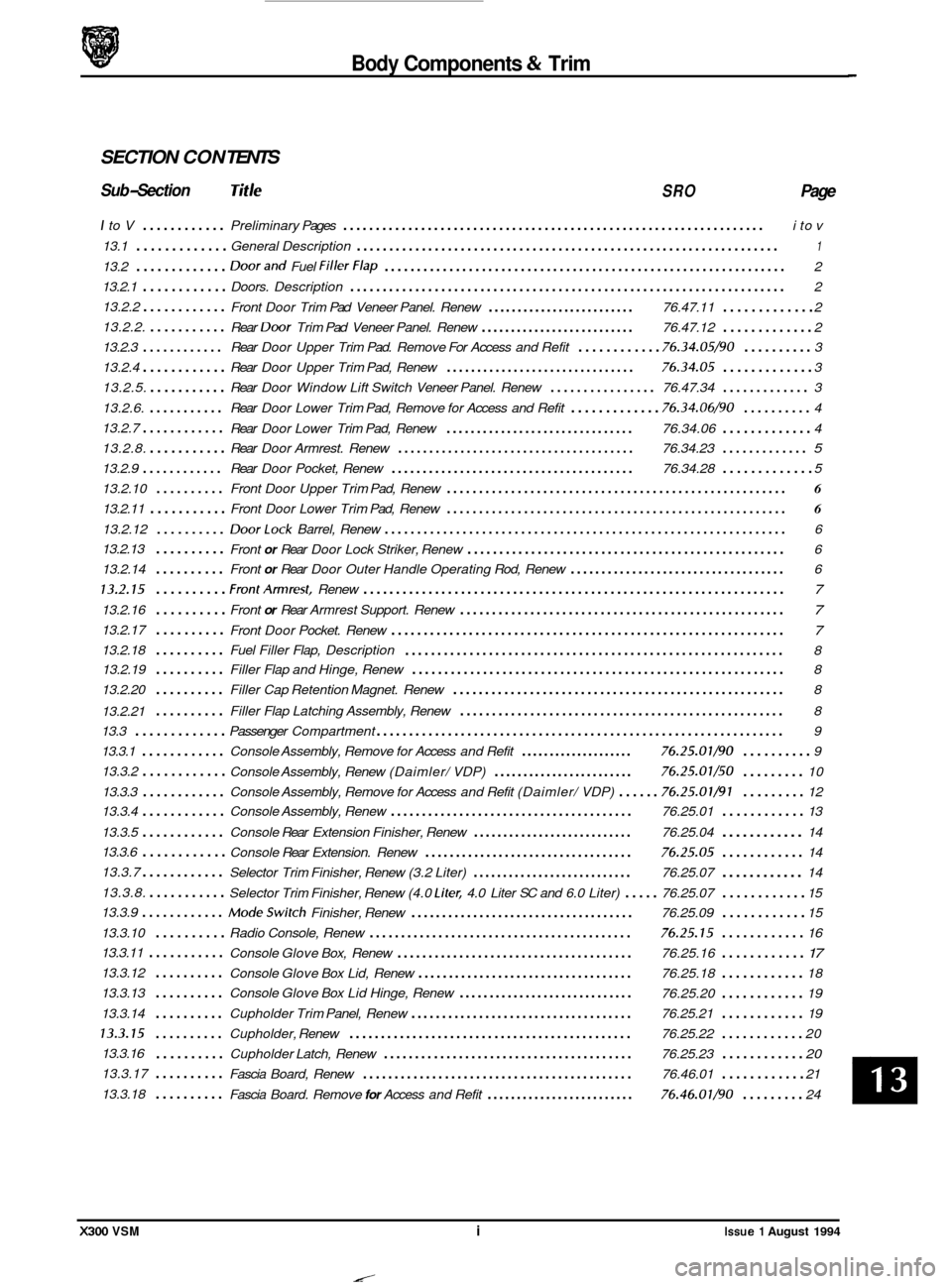
SECTION CON TENTS
Sub-Section Tit /e SRO Page
I to V ............ Preliminary Pages ................................................................. i to v
13.1
............. General Description ................................................................. 1
13.2 ............. Doorand Fuel FillerFlap .............................................................. 2
13.2.1
............ Doors. Description ................................................................... 2
13.2.2
............ Front Door Trim Pad Veneer Panel. Renew ......................... 76.47.11 ............. 2
13.2.2.
...........
13.2.3 ............ Rear Door Upper Trim Pad. Remove For Access and Refit ............ 76.34.05/90 .......... 3
13.2.5.
........... Rear Door Window Lift Switch Veneer Panel. Renew ................ 76.47.34 ............. 3
13.2.6.
........... Rear Door Lower Trim Pad, Remove for Access and Refit ............. 76.34.06/90 .......... 4
13.2.7
............ Rear Door Lower Trim Pad, Renew ............................... 76.34.06 ............. 4
13.2.8.
........... Rear Door Armrest. Renew ...................................... 76.34.23 ............. 5
13.2.9 ............ Rear Door Pocket, Renew ....................................... 76.34.28 ............. 5
13.2.10 .......... Front Door Upper Trim Pad, Renew ..................................................... 6
13.2.11 ........... Front Door Lower Trim Pad, Renew ..................................................... 6
13.2.12 .......... DoorLock Barrel, Renew .............................................................. 6
13.2.13 Front
or Rear Door Lock Striker, Renew .................................................. 6
13.2.14
.......... Front or Rear Door Outer Handle Operating Rod, Renew ................................... 6
13.2.15 .......... FrontArmrest, Renew ................................................................. 7
13.2.16 .......... Front or Rear Armrest Support. Renew ................................................... 7
13.2.17 .......... Front Door Pocket. Renew ............................................................. 7
........................................................... 8
Rear
Door Trim
Pad Veneer Panel. Renew .......................... 76.47.12 ............. 2
13.2.4
............ Rear Door Upper Trim Pad, Renew ............................... 76.34.05 ............. 3
..........
13.2.18 .......... Fuel Filler Flap, Description
13.2.19
.......... Filler Flap and Hinge, Renew .......................................................... 8
13.2.20
.......... Filler Cap Retention Magnet. Renew .................................................... 8
.......... Filler Flap Latching Assembly, Renew ................................................... 8
13.2.21
13.3
............. Passenger Compartment ............................................................... 9
13.3.1
............ Console Assembly, Remove for Access and Refit .................... 76.25.01/90 .......... 9
13.3.2
............ Console Assembly, Renew (Daimler/ VDP) ........................ 76.25.07/50 ......... 10
13.3.3
............ Console Assembly, Remove for Access and Refit (Daimler/ VDP) ...... 76.25.01/91 ......... 12
13.3.4
............ Console Assembly, Renew ....................................... 76.25.01 ............ 13
13.3.5
............ Console Rear Extension Finisher, Renew ........................... 76.25.04 14
Selector Trim Finisher, Renew (3.2 Liter)
........................... 76.25.07 ............ 14
Modeswitch Finisher, Renew .................................... 76.25.09 ............ 15
13.3.10
.......... Radio Console, Renew .......................................... 76.25.15 ............ 16
Console Glove Box, Renew
...................................... 76.25.16 ............ 17
Console Glove Box Lid, Renew ................................... 76.25.18 ............ 18
.......... Console Glove Box Lid Hinge, Renew ............................. 76.25.20 ............ 19
13.3.14
.......... Cupholder Trim Panel, Renew .................................... 76.25.21 ............ 19
13.3.15 .......... Cupholder, Renew ............................................. 76.25.22 ............ 20
.......... Cupholder Latch, Renew ........................................ 76.25.23 ............ 20
Fascia Board, Renew ........................................... 76.46.01 ............ 21
13.3.6
............ Console
Rear Extension. Renew .................................. 76.25.05 ............ 14
13.3.7
............
13.3.8. ........... Selector Trim Finisher, Renew (4.0 Liter, 4.0 Liter SC and 6.0 Liter) ..... 76.25.07 ............ 15
13.3.9
............
............
13.3.11 ...........
13.3.12
13.3.13 ..........
13.3.16
13.3.17
..........
13.3.18 .......... Fascia Board. Remove for Access and Refit ......................... 76.46.01/90 ......... 24
X300 VSM i Issue 1 August 1994
Page 256 of 521

Body Components & Trim
13.1 GENERAL DESCRIPTION
This section covers the following areas of the vehicle body:
0 Battery cover
0 Carpets - passenger compartment, trunk
0 Console - including radio, glovebox
0 Doors -frames, sealing, locks, trim, glazing
0 Fascia
0 Fuel filler flap assembly
0 Footrest
0 Hood - liners, gas strut, locking,
0 Illuminated sunvisor - inc mirror
0 Interior trim - trim pads, finishers, veneers
0 Mirrors - internal, external
0 Rear parcel tray
0 Roof console
0 Roof lining (headlining)
o Seats -front, rear -
0 Seat belts - front, rear
0 Sliding roof
0 Steering column cowl
0 Underscuttle pad
Refer to Appendix
A4 - Body Systems & Body Repair for information relating to crash-damage repairs and to the fol- lowing external components: exterior trim, bumpers, windscreen and rear screen, closures and sealing.
Refer to Section 15, Electrical for details of the following motors and solenoids: driver's and interior mirrors, window
lift, sunroof, seat / headrest and locking mechanisms (doors, trunk and filler cap).
Refer to Section 15, Electrical and Electrical Diagnostic Manual (EDM) for details of the passenger and driver airbags.
X300 VSM 1 Issue 1 August 1994
Page 257 of 521

Body Components & Trim d-!P
13.2
13.2.1 Doors, Description
Doors are of welded, mild steel frames welded to the door panels; sponge rubber primary and secondary seals are
mounted on the doors. Internal insulation is provided by a foam water shedder attached to the door by press fitting and doublesided adhesive tape.
Front and rear door armrests are attached to supports riveted to each door frame; the attaching screws are fitted
with access covers. Upper and lower trim pads and a door pocket are attached to each of the doors by clips and screws. multi-plug connectors are used to provide a means of connecting the guard lamps, window lift switches and loud- speakers, external mirror and regulator (front doors only), which are housed within the doors.
Central locking is provided subject to market variations: Dead Locking for UK
/ Europe and Driver only unlock for N America. Door locks are eight disc, bayonet fixing, barrels with integral lock / unlock switches. Keys include ‘in-key’
transponders which are programmed to the vehicle via the Jaguar Diagnostic System also operate the engine immobi
- lisation system.
CAUTION: When removing the door panel water shedder, a foam membrane attached to each door panel by a com- bination of pressfitting (upper area) and bydouble-sided tape (bottom area), it is important that the shed- der is refitted correctly to maintain the water seal.
It is advisable not to disturb the bottom (taped) portion of the water shedder unless absolutely necessary
- it is possible to unclip the top of the shedder and bend it over to gain access to the inner panel.
If
it is necessary to disturb the bottom attachment, eg to remove the water shedder from the door panel,
the existing water shedder must be discarded and a new one fitted to ensure that the seal is maintained.
On refitting, the new water shedder should be pressed onto the door panel at the top and then the adhes- ive tape backing strip peeled off to enable the shedder to be pressed home at the bottom.
DOORS AND FUEL FILLER FLAP
13.2.2 front and Rear Door Trim Pad Veneer Panel,
Renew
SRO 76.47.11
76.47.12
. Reposition the inner door handle. See Fig. 1.
Remove the inner handle escutcheon plate blanking plate.
Undo and remove the inner handle escutcheon plate se-
. Remove the plate and gasket.
. Carefully Undo and remove the veneer panel.
Undo and remove the retaining clip securing screws.
. Remove the retaining clip assemblies.
9 Place the veneer panel aside.
Place the new veneer panel to the front.
Fit the retaining clip assemblies.
. Fit and tighten the retaining clip securing screws.
. Fit and fully seat the veneer panel to the door.
. Reposition the inner door handle.
. Fit the gasket and plate over the inner door handle.
. Fit and tighten the escutcheon plate securing screw.
. Refit the blanking plate.
curing
screw.
Fig.
1
0
0
0
0
Issue 1 August 1994 2 X300 VSM
Page 258 of 521

Body Components & Trim
13.2.3 Rear
Door Upper Trim Pad - Remove For Access
And Refit
SRO 76.34.05/90
. Remove the rear door trim pad veneer panel, see sub-sec-
9 Undo and remove the upper trim panel securing screws.
. Lift to release the panel from the door mounting and re-
. Fit the trim pad and fully seat on the door mounting posi-
. Fit and tighten the trim pad securing screws.
. Refit the veneer panel.
tion
13.2.2.
move
the panel.
tion.
13.2.4
SRO 76.34.05
. Remove the rear door trim pad veneer panel, see sub-sec-
. Undo and remove the upper trim panel securing screws.
. Lift the panel to release from the door mounting and re-
. Undo and remove the chrome strip securing screws.
. Remove the chrome strip.
Undo and remove the top channel securing nuts.
. Displace and remove the top channel assembly.
. Place the trim pad aside.
. Place new trim pad to the front.
. Fit the upper channel to the trim pad.
. Fit and tighten the channel securing nuts.
. Fit the chrome strip.
. Fit and tighten the chrome strip securing screws.
Fit the trim pad and fully seat on the door mounting posi-
. Fit and tighten the trim pad securing screws.
. Refit the veneer panel.
Rear Door Upper Trim Pad, Renew
tion 13.2.2.
move the panel.
tion.
13.2.5 Rear Door Window Lift Switch Veneer Panel,
Renew
SRO 76.47.34 0
. Displace and remove the window lift assembly end cover
9 Undoand removetheveneer panel to switch assemblyse-
. Displace and remove the veneer panel from the forward
trim pad, Fig. 2.
curing screw.
securing clip. Place panel aside.
clip.
. Fit and fully seat new veneer panel to the forward securing
. Fit and fully tighten the panel securing screw.
. Fit and fully seat the switch assembly end trim pad.
Fig. 1
Issue 1 August 1994 X300 VSM 3 ~~ ~~
Page 259 of 521

Body Components & Trim -
13.2.6
SRO 76.34.06/90
Remove the rear door armrest, see sub-section 13.2.8.
From inside the door pocket, release the puddle lamp (1
. Disconnect the multi-plugs (1 Fig. 2) and removethe lamp.
. Carefully displace the trim pad (2 Fig. 1) from the door re-
. Displace trim pad from the upper retaining tang (3 Fig. 1).
Disconnect the door speaker multi-plug (2 Fig. 2) and the
9 Feed the lamp harness through the trim pad and lowerthe
. Position the trim pad to the vehicle.
. Feed the puddle lamp harness through the trim pad.
Connect the window lift switch and speaker multi-plugs.
. Locate the trim pad upper retaining tang.
. Fit and fully seat the trim pad retaining clips.
Place the puddle lamp to position.
. Connect the lamp multi-plugs.
. Fit and align the puddle lamp to the door pocket and se-
Refit the armrest.
Rear Door lower Trim Pad- Remove For Access
And Refit
Fig. 1) securing quarter turn fastener.
taining clips.
window
lift switch multi-plug (3 Fig. 2).
trim pad assembly.
cure with the lamp securing quarter turn fastener.
13.2.7 Rear Door lower Trim Pad, Renew
SRO 76.34.06
. Remove the rear door armrest, see sub-section 13.2.8.
. From inside the door pocket, release the puddle lamp (1
Disconnect lamp multi-plugs (1 Fig. 2) and remove lamp.
Displace the trim panel (2 Fig. 1) from door retaining clips.
. Displace trim pad from the upper retaining tang (3 Fig. 1).
. Disconnect the door speaker multi-plug (2 Fig. 2) and the
. Feed the lamp harness through the trim pad and lowerthe
. Remove the rear door pocket, see sub-section 13.2.9.
. Displace and remove the retaining clips and remove the
. Place the new door trim pad to the front.
Fit and fully seat the trim pad retaining clips.
. Refit the rear door pocket.
. Position the trim pad to the vehicle.
. Feed the puddle lamp harness through the trim panel.
. Connect the window lift switch and speaker multi-plugs.
. Locate the trim pad upper retaining tang.
. Fit and fully seat the trim pad retaining clips.
. Place the puddle lamp to position.
Connect the lamp multi-plugs.
. Fit and align the puddle lamp to the door pocket and se-
. Refit the armrest.
Fig. 1) securing quarter turn fastener.
window
lift switch multi-plug (3 Fig. 2).
trim pad assembly.
trim..
cure with the lamp securing quarter turn fastener.
Fig. 1
J76-1085
Fig. 2
0
0
0
0
4 X300 VSM Issue 1 August 1994
Page 260 of 521

Body Components & Trim 4-5
13.2.8 Rear Door Armrest, Renew
SRO 76.34.23
. Displace and remove the armrest securing screw hole
. Undo and remove the armrest securing screws (2 Fig. 1)
. Remove the armrest screw hole plastic finishers (3 Fig. 1).
. Undo and remove the chrome finisher securing screws.
. Undo and remove the armrest inner black finisher secur-
ing screws.
. Displace and remove the finisher.
. Place the armrest aside.
. Place the new armrest to the front.
. Fit and align the inner trim finisher.
Fit and tighten the finisher securing screws.
. Fit and align the armrest chrome finisher.
. Fit and tighten the finisher securing screws.
. Fit and seat armrest securing screw hole plastic finishers.
. Position the armrest assembly. Fit and tighten the armrest
. Fit and seat the armrest screw hole plastic finisher covers.
plastic finisher covers
(1 Fig. 1).
and remove
the armrest assembly.
securing screws.
13.2.9 Rear Door Pocket, Renew
SRO 76.34.28
. Remove the rear door armrest, see sub-section 13.2.8.
. Remove the lower trim pad, see sub-section 13.2.6.
. Undo and remove the rear door pocket to trim pad secur-
. Displace and remove the rear window lift switch assembly
. Undo and remove the veneer panel to switch assembly se-
. Displace and remove the veneer panel from the forward
. Undo and remove the switch assembly securing screws /
. Displace and remove the switch assembly.
. Undo and remove the speaker securing screws and re-
. Displace and remove the speaker grille.
. Place the door pocket aside.
. Place new rear door pocket to the front.
. Fit and fully seat the speaker grille.
. Position the speaker and fit the speaker securing screws.
. Fit and align the window lift switch assembly.
. Fit and tighten the switch assembly securing screws/nuts.
. Fit and fully seat the veneer panel to the front securing clip.
. Fit and tighten the veneer panel securing screw.
. Fit and fully seat the switch end cover trim pad.
9 Position the door pocket to lower trim pad and fit and
tighten the door pocket securing screws.
. Refit the door lower trim pad.
Refit the rear door armrest.
ing screws (Fig. 2). Remove the door pocket.
end cover
trim pad (Fig. 3).
curing screw (Fig. 3).
securing clip (Fig. 3).
nuts (Fig. 3).
move the speaker.
\L--
I
J76-771
Fia. 1
J76
J76
Fig. 2
.713
Fia. 3
X300 VSM 5 Issue 1 August 1994
Page 261 of 521

Body Components & Trim -
13.2.10 Front Door Upper Trim Pad, Renew
. Disconnect vehicle battery ground lead.
. Remove the front door veneer panel.
. Remove the upper trim pad securing clip and screws.
. Lift the trim pad to release it from the door and remove the
To refit, carry out reversal of the above procedure.
inner
waist rail seal.
13.2.1 1 Front Door lower Trim Pad, Renew
. Disconnect vehicle battery ground lead.
Remove armrest.
. From inside door pocket, release guard retainer, discon-
. Carefully prise the trim pad away from the door and re-
With the trim pad moved for access, disconnect loud-
. Feed guard lamp harness through aperture and place trim
. Remove front door pocket and trim pad retainers.
. To refit, carry out reversal of the above procedure. Check
the trim pad retainers for damage before refitting.
nect
multi
-plug and remove lamp.
lease from the upper retainer.
speaker and window
lift switch multi-plugs.
pad on a clean workbench.
13.2.12 Door lock Barrel, Renew
. Disconnect vehicle battery ground lead.
. Remove the door trim veneer, door upper trim pad, door
. Remove the handle assembly to a clean workbench.
. Remove the lock barrel from its bayonet type mounting.
. Carefully remove the barrel components noting the order
. To refit, carry out reversal of the above procedure, ensur-
lower trim pad and door handle.
and position if reassembly is required.
ing that the components are lightly greased.
13.2.13 Front or Rear Door Lock Striker, Renew
. Note position of striker before removal.
. Remove two screws attaching striker to pillar.
Remove striker from pillar.
. To refit, carry out reversal of the above procedure, ensur- ing that the striker is correctly aligned with the door lock
before final torque tightening.
13.2.14 Front or Rear Door Outer Handle Operating
Rod, Renew
. Disconnect vehicle battery ground lead.
. Remove the door trim veneer, door upper trim pad, door
lower trim pad.
. Disengage the handle operating rod retaining clip and free
the rod from the operating pivot.
. Allowthe latch levertocontact the release mechanism, re- position the operating rod and replace the retaining clip.
. Check that the setting is correct by operating the door
mechanism.
To refit, carry out reversal of the above procedure.
/ 2 176 -1053
1. Water shedder 2. Multi connector 3. Armrest support
Fig. 1 Door Interior Components
Issue 1 August 1994 6 X300 VSM
Page 346 of 521

15.1.13 Spillage and Leakage
If material is spilled or released,contact Jaguar Service for clean up procedures. All other personnel must be kept away
from contaminated area.
Do not dispose contaminated propellant or water into storm or sanitary sewers, ground water or soil.
Spills may be reportable to local state,
and/or federal authorities.
Material should
be disposed of by incineration or chemical oxidation under carefully controlled conditions by specially
trained individuals in accordance with local State and Federal regulations.
0
15.1.14 Scrapping Vehicles With Live Airbag(s)
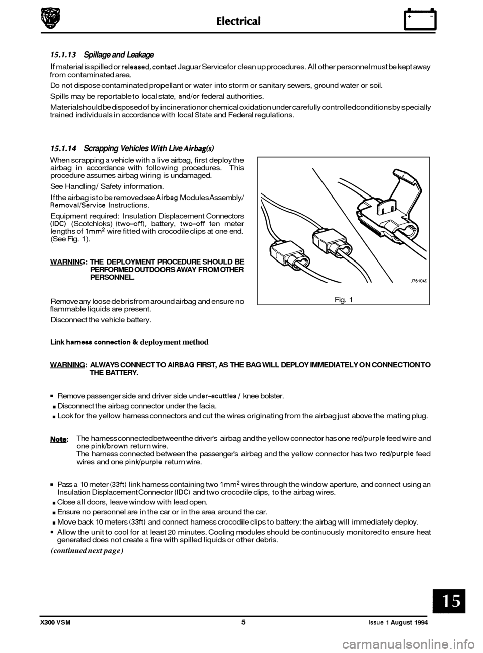
When scrapping a vehicle with a live airbag, first deploy the
airbag in accordance with following procedures. This
procedure assumes airbag wiring is undamaged.
See Handling
/ Safety information.
If the airbag is
to be removed see Airbag Modules Assembly/ Removal/Service Instructions.
Equipment required: Insulation Displacement Connectors
(IDC) (Scotchloks) (two-off), battery, two-off ten meter
lengths of lmm2 wire fitted with crocodile clips at one end. (See Fig. 1).
WARNING: THE DEPLOYMENT PROCEDURE SHOULD BE PERFORMED OUTDOORS AWAY FROM OTHER
PERSONNEL.
Remove any loose debrisfrom around airbag and ensure no
flammable liquids are present.
Disconnect the vehicle battery. Fig. 1
Link harness conn&ion & deployment method
WARNING:
ALWAYS CONNECT TO AlRBAG FIRST, AS THE BAG WILL DEPLOY IMMEDIATELY ON CONNECTION TO
THE BATTERY.
Remove passenger side and driver side under-scuttles / knee bolster.
. Disconnect the airbag connector under the facia.
. Look for the yellow harness connectors and cut the wires originating from the airbag just above the mating plug.
w: The harness connected between the driver's airbag and the yellow connector has one red/purple feed wire and
one pinkbrown return wire.
The harness connected between the passenger's airbag and the yellow connector has two
red/purple feed
wires and one pinwpurple return wire.
Pass a 10 meter (33ft) link harness containing two lmm2 wires through the window aperture, and connect using an
. Close all doors, leave window with lead open.
. Ensure no personnel are in the car or in the area around the car.
. Move back 10 meters (33ft) and connect harness crocodile clips to battery: the airbag will immediately deploy.
Allow the unit to cool for at least 20 minutes. Cooling modules should be continuously monitored to ensure heat
(continued next page)
Insulation Displacement Connector (IDC) and two crocodile clips, to the airbag wires.
generated does not create
a fire with spilled liquids or other debris.
X300 VSM 5 Issue 1 August 1994
Page 371 of 521

15.11 MOTORS & SOLENOIDS ~
5.1 1.1 General
Description
Electrical
I# b
Fig. 1 Motors & Solenoids
-
1695
Fig. 1 shows a plan view of all motors located inside the trunk, the passenger compartment and the engine bay. The
motors drive various devices to perform certain functions such wipe / wash operations, window lift operations, seat
operations etc.
In order to carry out remove and refit operations, the annotated illustration is to be read in conjunction with the table
shown on the following page. This lists
all the motors and solenoids.
Some motors can be accessed by removing the various trims, the carpet, or carpet sections, other can be located
through carrying out
a visual inspection around the engine bay, the cab and the trunk.
To avoid any accidents such as electric shocks, always disconnect the battery negative lead from the battery negative
terminal before disconnecting any of the listed cables.
Issue 1 August 1994 30 X300 VSM
Page 399 of 521

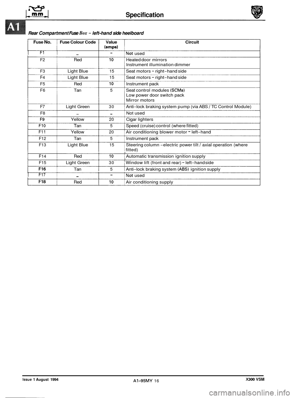
Specification
Rear Compartment Fuse Box - left-hand side heelboard
Fuse No. Fuse Colour Code Value Circuit
(amps)
I F1 I - I - lNot used
F2 Red 10 Heated door mirrors
F3 Light Blue 15 Seat motors - right-hand side
F4 Light Blue 15 Seat motors - right-hand side
F5 Red 10 Instrument pack
F6 Tan 5 Seat control modules (SCMs)
Low power door switch pack
Mirror motors
Instrument
illumination dimmer
F7 Light Green 30 Anti-lock braking system pump (via ABS / TC Control Module)
F8 - - Not used
F9 Yellow 20 Cigar lighters
FIO Tan 5 Speed (cruise) control (where fitted)
F11 Yellow 20 Air conditioning blower motor - left-hand
F12 Tan 5 Instrument pack
F13 Light Blue 15 Steering column -electric power tilt / axial operation (where
j fitted) 1 I I F14 Red 10 i Automatic transmission ignition supply I I I F15 Light Green 30 I Window lift (front and rear) - left-hand side
Tan
I 5 1 Anti-lock braking system (ABS) ignition supply
I F17 1 - I - lNot used
Red
I 10 I Air conditioning supply
Rear Compartment Fuse Box - left-hand side heelboard ~~
X300 VSM Issue 1 August 1994 AI-95MY 16
0
0
0