drain bolt JAGUAR XJ6 1994 2.G Workshop Manual
[x] Cancel search | Manufacturer: JAGUAR, Model Year: 1994, Model line: XJ6, Model: JAGUAR XJ6 1994 2.GPages: 521, PDF Size: 17.35 MB
Page 79 of 521
Fuel, Emission Control & Engine Management (AJ16)
. Reposition fuel feed pipe from fuel rail union and fit blanking plugs to rail and pipe.
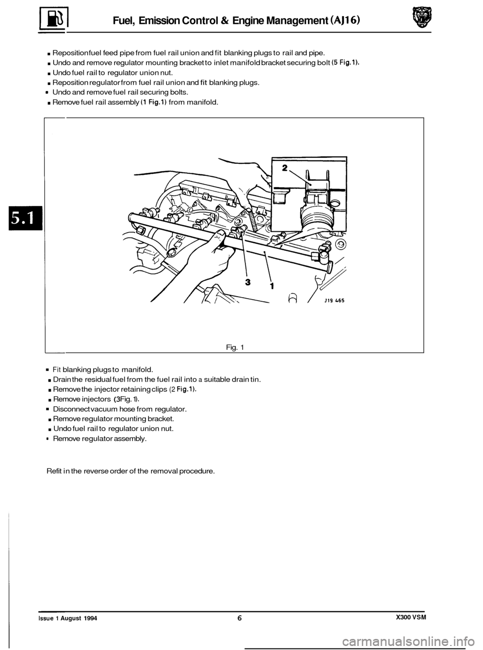
. Undo and remove regulator mounting bracket to inlet manifold bracket securing bolt (5 Fig.1).
. Undo fuel rail to regulator union nut.
. Reposition regulator from fuel rail union and fit blanking plugs.
. Remove fuel rail assembly (1 Fig.1) from manifold.
Undo
and remove fuel rail securing bolts.
Fig. 1
Fit blanking plugs to manifold.
. Drain the residual fuel from the fuel rail into a suitable drain tin.
. Remove the injector retaining clips (2 Fig.1).
. Remove injectors (3 Fig. 1 ).
Disconnect vacuum hose from regulator.
. Remove regulator mounting bracket.
. Undo fuel rail to regulator union nut.
= Remove regulator assembly.
Refit in the reverse order of the removal procedure.
X300 VSM Issue 1 August 1994 6
Page 81 of 521
Fuel, Emission Control & Engine Management (AJ16)
. Reposition fuel feed pipe from fuel rail union and fit blanking plugs to rail and pipe.
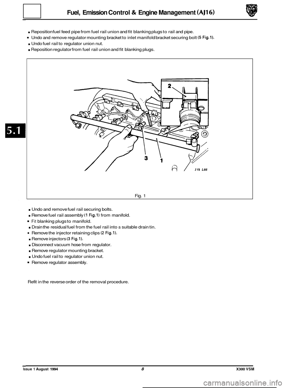
Undo and remove regulator mounting bracket to inlet manifold bracket securing bolt (5 Fig.1).
. Undo fuel rail to regulator union nut.
. Reposition regulator from fuel rail union and fit blanking plugs.
/ 119 L66
Fig. 1
. Undo and remove fuel rail securing bolts.
. Remove fuel rail assembly (1 Fig.1) from manifold.
Fit blanking plugs to manifold.
. Drain the residual fuel from the fuel rail into a suitable drain tin.
Remove the injector retaining clips (2 Fig.1).
. Remove injectors (3 Fig.1).
. Disconnect vacuum hose from regulator.
. Remove regulator mounting bracket.
. Undo fuel rail to regulator union nut.
Remove regulator assembly.
Refit in the reverse order of the removal procedure.
0
0
0
0
Issue 1 August 1994 8 X300 VSM
Page 120 of 521
Manual Transmission & Clutch (AJ16)
. Remove front clamp from unit lift.
. Raise / lower unit with jack, no stands.
. Traverse lift under ramp and take weight of transmission.
. Adjust jacking platform angles to suit transmission.
. Adjust side and rear clamps to suit transmission and tighten clamp wing nuts.
. Fit the safety chain assembly to left hand arm of lift, and secure with peg.
Pass safety chain over transmission and engage in front arm of lift. Tighten the safety chain adjuster.
. Remove remaining transmission to adaptor plate securing bolts and carefully lower transmission from engine.
. Remove transmission from ramp area.
. Remove clutch release bearing assembly from release lever.
. Remove clutch release lever retaining clip and remove lever.
. Remove release lever pivot pin.
Remove transmission switch.
. Remove rear mounting spring retainer securing nut.
. Reposition selector shaft pin cover.
0
Remove rear mounting spring retainer and remove rear mounting assembly.
Remove selector shaft yoke to selector shaft retaining pin and remove the yoke.
. Remove slave cylinder securing studs.
. Remove the transmission from the unit lift.
. Remove transmission drain plug and allow to drain, refit
the drain plug.
Fit new transmission to unit lift.
Fill transmission with oil and refit the level plug.
. Clean components and mating faces.
. Fit the slave cylinder mounting studs.
. Lubricate the selector output shaft.
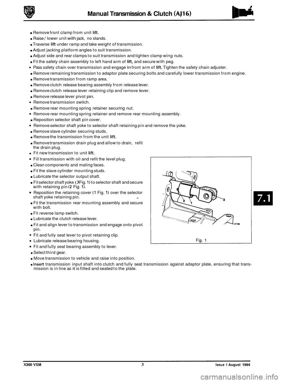
. Fit selector shaft yoke (3 Fig. 1) to selector shaft and secure
with retaining pin (2 Fig. 1).
Reposition the retaining cover (1 Fig. 1) over the selector
shaft yoke retaining pin. -
. Fit the transmission rear mounting assembly and secure
with bolt.
. Fit reverse lamp switch.
. Lubricate the clutch release lever.
. Fit and align lever to transmission and engage onto pivot
pin.
Fit and fully seat lever to pivot retaining clip.
= Lubricate release bearing housing.
9 Fit and fully seat bearing assembly to lever.
. Select third gear.
. Move transmission to vehicle and raise into position.
Fia. 1
. Insert transmission input shaft into clutch and fully seat transmission against adaptor plate, ensuring that trans- mission is in line as it is fitted and seated to the plate.
X300 VSM 3 Issue 1 August 1994
Page 137 of 521
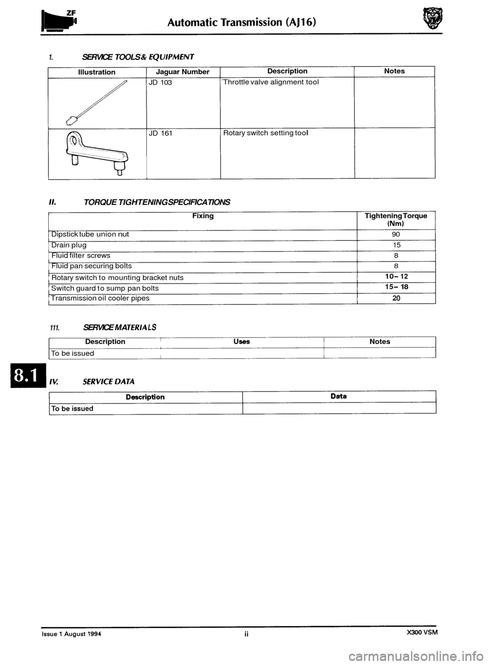
1. SERVICE TOOLS & fQUlPMENT
Illustration
::(())(((((
Jaguar Number
JD 103
JD 161
Description Notes
Throttle valve alignment tool
Rotary switch setting tool
11. TORQUE TIGHTENING SPECIFICATIONS
Fixing Tightening Torque
(Nm)
Dipstick tube union nut 90
Drain plug 15
Fluid filter screws 8
Fluid pan securing bolts 8
Rotary switch to mounting bracket nuts
Transmission oil cooler pipes
20
10- 12
15- 18 Switch guard to sump pan bolts
111. SERVICE MA TERlA L S
Description USeS Notes
To be issued
Page 148 of 521
Automatic Transmission (AJl6)
8.1.6 TRANSMISSION FLUID FILTER, RENEW
SRO 44.24.07
9 Raise the hood and fit a fender cover.
. Raise the vehicle on a ramp.
. Drain the transmission lubrication system, see Sub-sec-
. Removethefluid pan,seeSub-section8.1.7 (4,OL)orSub-
. Release and remove the fluid filter securing screws; dis-
. Remove and discard the filter '0' ring.
. Clean the new filter and mating faces.
. Fit the '0' ring to the new filter; fit and seat the filter assem-
. Fit and torque tighten the filter securing screws.
. Refitthefluidpan,seeSub-section8.1.7 (4,OL)orSub-sec-
. Lower the vehicle on the ramp.
. Refill the transmission unit with fluid, see Subsection
8.1.2.
Remove the fender cover and lower the hood.
(3,2L AND 4,011
tion 8.1.2.
section
8.1.8 (3,2L).
place and remove the fluid filter.
bly to the valve body.
tion 8.1.8
(3,2L).
8.1.7 FLUID PAN, RENEW (4,OL)
SRO 44.24.04
. Raise the hood and fit a fender cover.
. Raise the vehicle on a ramp.
. Drain the transmission lubrication system, see Sub-sec-
tion 8.1.2.
Release and remove the rotary switch protection cover to
fluid pan securing screws; remove the rotary switch
protect ion cover.
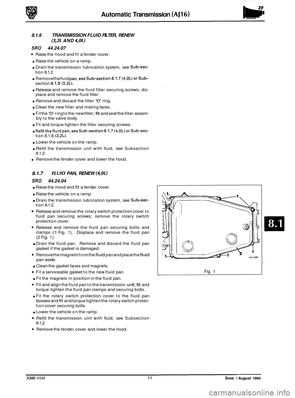
Release and remove the fluid pan securing bolts and
clamps
(1 Fig. 1). Displace and remove the fluid pan
(2 Fig. 1).
. Drain the fluid pan. Remove and discard the fluid pan
gasket if the gasket is damaged.
Remove the magnets from the fluid pan and place the fluid
pan aside.
. Clean the gasket faces and magnets.
Fit a serviceable gasket to the new fluid pan.
. Fit the magnets in position in the fluid pan.
Fit and align the fluid pan to the transmission unit; fit and
torque tighten the fluid pan clamps and securing bolts.
. Fit the rotary switch protection cover to the fluid pan
bosses and fit and torque tighten the rotary switch protec-
tion cover securing bolts.
. Lower the vehicle on the ramp.
Refill the transmission unit with fluid, see Subsection
Remove the fender cover and lower the hood.
8.1.2.
Fig. 1
X300 VSM 11 Issue 1 August 1994
Page 149 of 521
Automatic Transmission (AJ16)
8.1.8 FLUID PAN, RENEW (3,2L)
SRO 44.24.04
. Raise the vehicle on a ramp.
. Drain the transmission lubrication system, see Sub-sec-
tion 8.1.2.
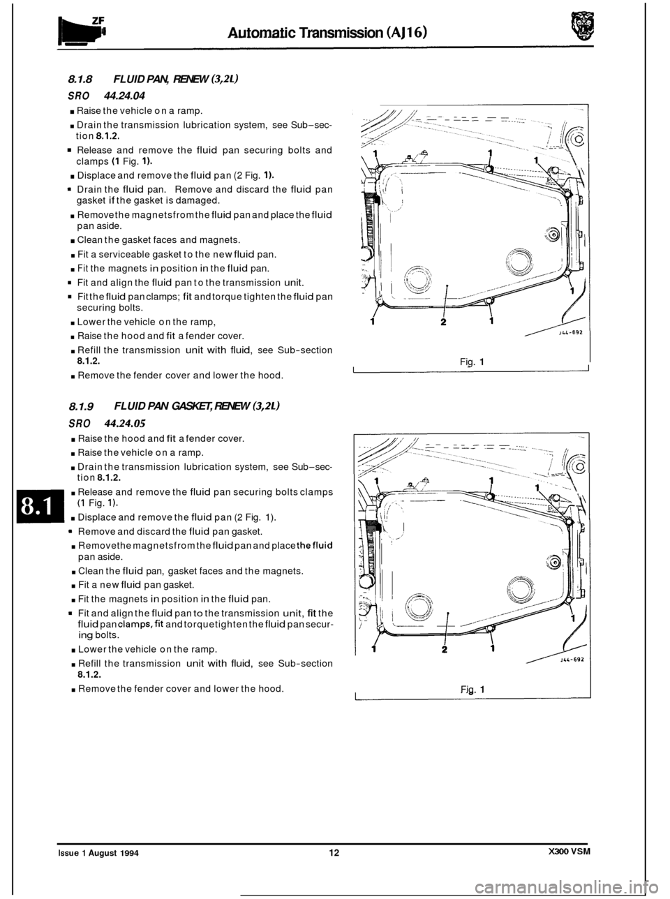
Release and remove the fluid pan securing bolts and
clamps
(1 Fig. 1).
. Displace and remove the fluid pan (2 Fig. 1).
= Drain the fluid pan. Remove and discard the fluid pan
. Remove the magnetsfrom the fluid pan and place the fluid
. Clean the gasket faces and magnets.
. Fit a serviceable gasket to the new fluid pan.
. Fit the magnets in position in the fluid pan.
9 Fit and align the fluid pan to the transmission unit.
Fit the fluid pan clamps; fit and torque tighten the fluid pan
. Lower the vehicle on the ramp,
. Raise the hood and fit a fender cover.
. Refill the transmission unit with fluid, see Sub-section
. Remove the fender cover and lower the hood.
gasket
if the
gasket is damaged.
pan aside.
securing bolts.
8.1.2.
8.1.9
SRO 44.24.05
. Raise the hood and fit a fender cover.
. Raise the vehicle on a ramp.
. Drain the transmission lubrication system, see Sub-sec-
FLUID PAN GASKET, RENEW (3,2L)
tion 8.1.2.
. Release and remove the fluid pan securing bolts clamps
. Displace and remove the fluid pan (2 Fig. 1).
(1 Fig. 1).
Remove and discard the fluid pan gasket.
pan aside.
. Removethe magnetsfrom the fluid pan and place thefluid
. Clean the fluid pan, gasket faces and the magnets.
. Fit a new fluid pan gasket.
. Fit the magnets in position in the fluid pan.
9 Fit and align the fluid pan to the transmission unit, fit the
fluid pan clamps,fit and torquetighten the fluid pan secur-
ing bolts.
. Lower the vehicle on the ramp.
. Refill the transmission unit with fluid, see Sub-section
. Remove the fender cover and lower the hood.
8.1.2.
/>U492
Fig. 1
Fig. 1
j
X300 VSM Issue 1 August 1994 12
Page 161 of 521
Automatic Transmission (V12 & AJ16 Supercharged) Powertrain
8.2.3
SRO 44.15.39
. Open the hood and fit a suitable fender cover.
9 Raise the vehicle on a ramp.
. Drain the transmission lubrication system, see Subsec-
. Remove the fluid pan, see Sub-section 8.2.14 (4,OL SC) or
. Remove the fluid filter, see Sub-section 8.2.18.
Disconnect the internal harness plug from the pressure
Release and remove the pressure switch manifold to valve
. Remove the manifold from the valve body.
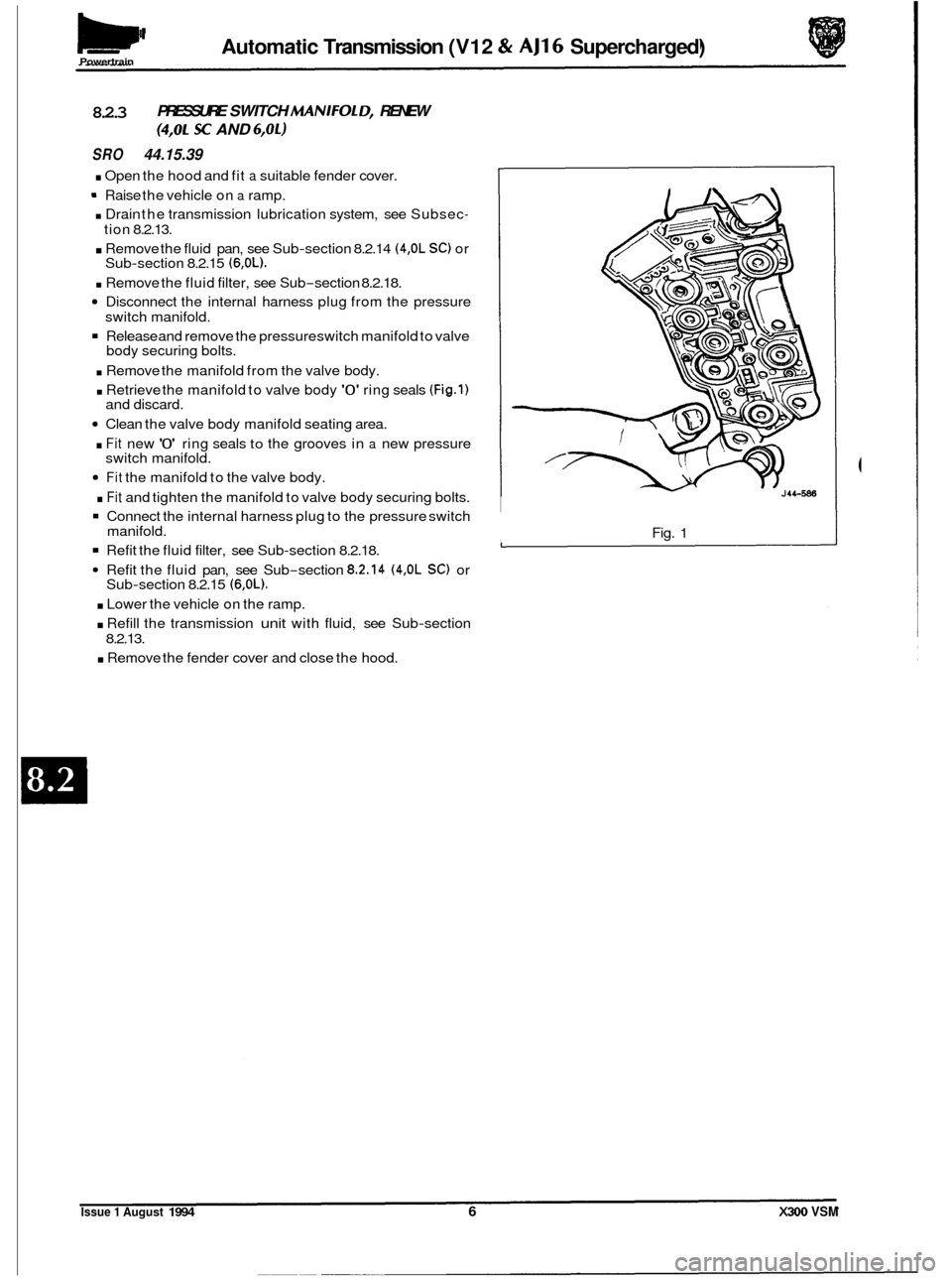
. Retrieve the manifold to valve body '0' ring seals (Fig.1)
Clean the valve body manifold seating area.
. Fit new '0' ring seals to the grooves in a new pressure
Fit the manifold to the valve body.
. Fit and tighten the manifold to valve body securing bolts.
Connect the internal harness plug to the pressure switch
Refit the fluid filter, see Sub-section 8.2.18.
Refit the fluid pan, see Sub-section 8.2.14 (4,OL SC) or
. Lower the vehicle on the ramp.
. Refill the transmission unit with fluid, see Sub-section
. Remove the fender cover and close the hood.
PRESSURE SWITCH MANIFOL D, RENEW
(4,OL SC AND 6,OL)
tion 8.2.13.
Sub
-section 8.2.15 (6,OL).
switch manifold.
body securing bolts.
and discard.
switch manifold.
manifold.
Sub
-section 8.2.15 (6,OL).
8.2.13. Fig.
1
Issue 1 August 1994 6 X300 VSM
Page 170 of 521
Pomrtrain Automatic Transmission (V12 & AJ16 Supercharged)
8.2.14 FLUID PAN, RENEW (4,OL SC)
SRO 44.24.04
. Open the hood and fit a suitable fender cover.
. Raise the vehicle on a ramp.
. Drain the transmission lubrication system, see Sukec-
. Slacken the downpipe catalyst to intermediate catalyst
Slacken the intermediate catalyst to intermediate si-
9 Disconnect the intermediate catalyst pipe from the down-
. Clean the downpipe and intermediate pipe joint.
. Release and remove the fluid pan securing bolts.
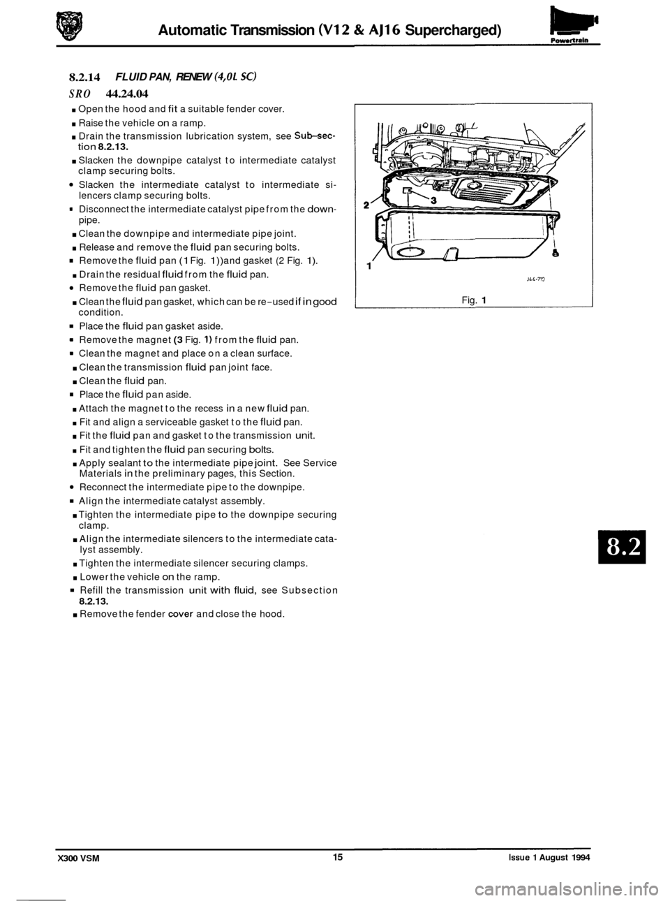
Remove the fluid pan (1 Fig. 1)) and gasket (2 Fig. 1).
. Drain the residual fluid from the fluid pan.
Remove the fluid pan gasket.
. Clean the fluid pan gasket, which can be re-used if in good
Place the fluid pan gasket aside.
= Remove the magnet (3 Fig. 1) from the fluid pan.
= Clean the magnet and place on a clean surface.
. Clean the transmission fluid pan joint face.
. Clean the fluid pan.
Place the fluid pan aside.
. Attach the magnet to the recess in a new fluid pan.
. Fit and align a serviceable gasket to the fluid pan.
. Fit the fluid pan and gasket to the transmission unit.
. Fit and tighten the fluid pan securing bolts.
. Apply sealant to the intermediate pipe joint. See Service
Materials in the preliminary pages, this Section.
Reconnect the intermediate pipe to the downpipe.
Align the intermediate catalyst assembly.
. Tighten the intermediate pipe to the downpipe securing
. Align the intermediate silencers to the intermediate cata-
. Tighten the intermediate silencer securing clamps.
. Lower the vehicle on the ramp.
Refill the transmission unit with fluid, see Subsection
8.2.13.
. Remove the fender cover and close the hood.
tion 8.2.13.
clamp securing bolts.
lencers clamp securing bolts.
pipe.
condition.
clamp. lyst assembly.
.. rli
i
1
JLL-713
Fig. 1
X300 VSM 15 Issue 1 August 1994
Page 171 of 521
Automatic Transmission (V12 & AJ16 Supercharged) Powertrain
8.2.15 FlUlD PAN, RENEW (6,Ol)
SRO 44.24.04
Open the hood and fit a suitable fender cover.
. Raise the vehicle on a ramp.
. Slacken the underfloor catalyst to downpipe clamps se-
. Displace and reposition the olive clamps on the pipes.
. Slacken the underfloor catalyst to intermediate silencer
Displace the underfloor catalyst assembly rearwards to
. Displace and remove the olives from the downpipes.
. Using a wire brush, clean the olives and downpipe joints.
m Place a suitable piece of wood between the underfloor
Drain the transmission lubrication system, see Sub-sec-
Release and remove the fluid pan securing bolts.
Drain the residual fluid from the fluid pan.
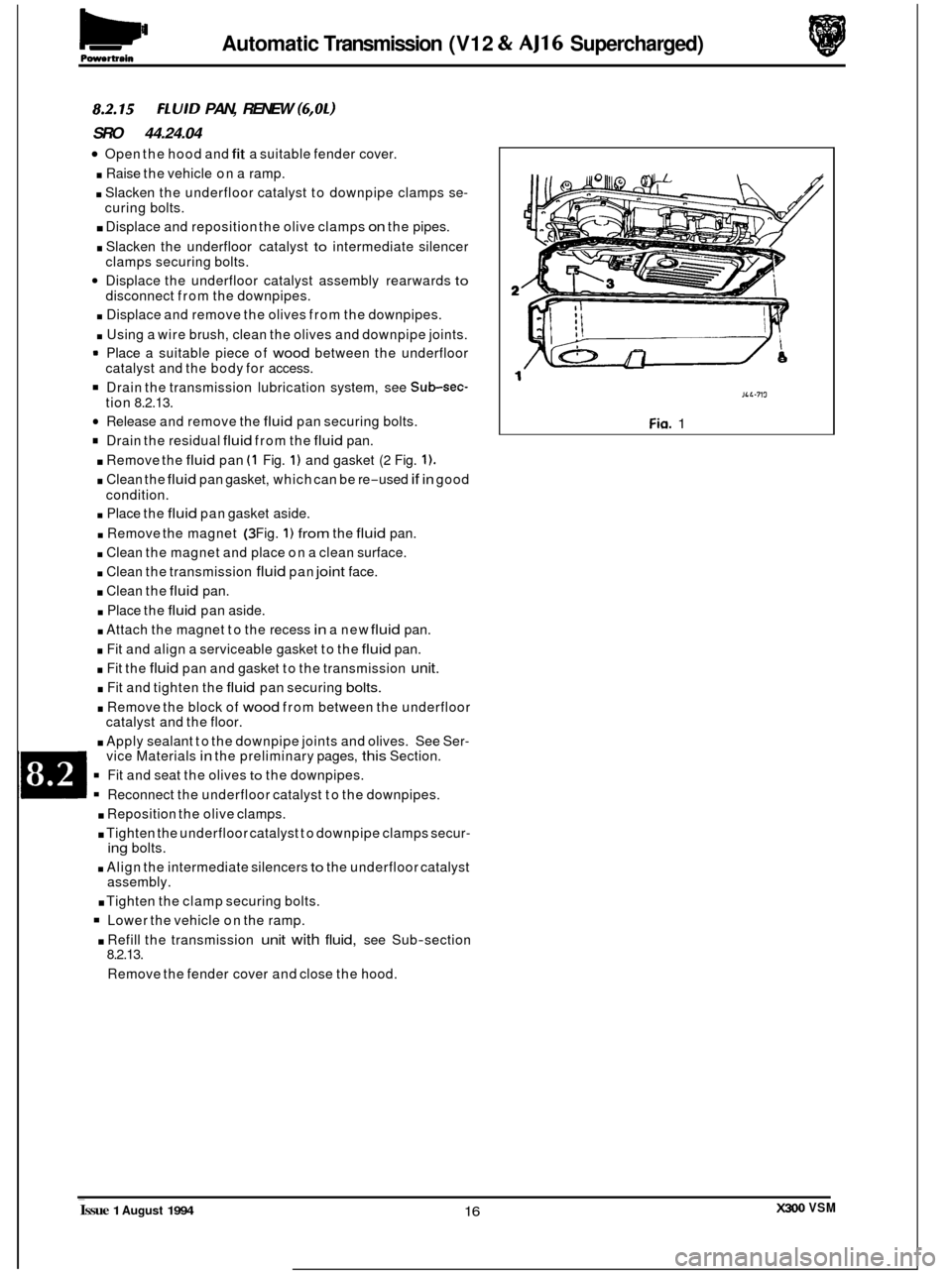
. Remove the fluid pan (1 Fig. 1) and gasket (2 Fig. 1).
. Clean the fluid pan gasket, which can be re-used if in good
. Place the fluid pan gasket aside.
. Remove the magnet (3 Fig. 1) from the fluid pan.
. Clean the magnet and place on a clean surface.
. Clean the transmission fluid pan joint face.
. Clean the fluid pan.
. Place the fluid pan aside.
. Attach the magnet to the recess in a new fluid pan.
. Fit and align a serviceable gasket to the fluid pan.
. Fit the fluid pan and gasket to the transmission unit.
. Fit and tighten the fluid pan securing bolts.
. Remove the block of wood from between the underfloor
catalyst and the floor.
. Apply sealant to the downpipe joints and olives. See Ser- vice Materials in the preliminary pages, this Section.
Fit and seat the olives to the downpipes.
Reconnect the underfloor catalyst to the downpipes.
. Reposition the olive clamps.
. Tighten the underfloor catalyst to downpipe clamps secur-
. Align the intermediate silencers to the underfloor catalyst
. Tighten the clamp securing bolts.
Lower the vehicle on the ramp.
. Refill the transmission unit with fluid, see Sub-section
curing
bolts.
clamps securing bolts.
disconnect from the downpipes.
catalyst and the body for access.
tion 8.2.13.
condition.
ing bolts.
assembly.
8.2.13. Remove the fender cover and close the hood.
JLL-719
Fin. 1 ~
Issue 1 August 1994 X300 VSM 16
Page 172 of 521
Powertrain Automatic Transmission (V12 & AJ16 Supercharged)
8.2.16 FLUID PAN GASKET, RENEW (4,OL SC)
SRO 44.24.05
Open the hood and fit a suitable fender cover.
. Raise the vehicle on a ramp.
Drain the transmission lubrication system, see Sub-sec-
. Slacken the downpipe catalyst to intermediate catalyst
. Slacken the intermediate catalyst to intermediate si-
. Disconnect the intermediate catalyst pipe from the down-
Clean the downpipe and intermediate pipe joint.
. Release and remove the fluid pan securing bolts.
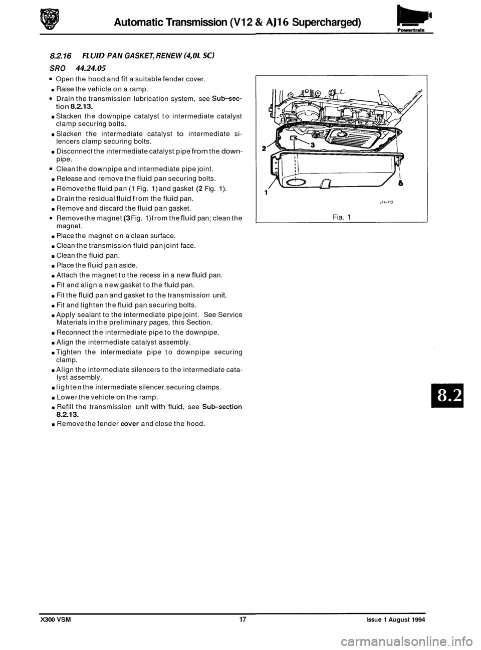
. Remove the fluid pan (1 Fig. 1) and gasket (2 Fig. 1).
. Drain the residual fluid from the fluid pan.
. Remove and discard the fluid pan gasket.
Remove the magnet (3 Fig. 1) from the fluid pan; clean the
. Place the magnet on a clean surface.
. Clean the transmission fluid pan joint face.
. Clean the fluid pan.
. Place the fluid pan aside.
. Attach the magnet to the recess in a new fluid pan.
. Fit and align a new gasket to the fluid pan.
. Fit the fluid pan and gasket to the transmission unit.
. Fit and tighten the fluid pan securing bolts.
. Apply sealant to the intermediate pipe joint. See Service
Materials in the preliminary pages, this Section.
. Reconnect the intermediate pipe to the downpipe.
. Align the intermediate catalyst assembly.
. Tighten the intermediate pipe to downpipe securing
. Align the intermediate silencers to the intermediate cata-
. lighten the intermediate silencer securing clamps.
. Lower the vehicle on the ramp.
tion 8.2.13.
clamp securing bolts.
lencers clamp securing bolts.
pipe.
magnet.
clamp. lyst assembly.
. Refill the transmission unit with fluid, see Subsection
8.2.13.
. Remove the fender cover and close the hood.
1
JLL-713
Fia. 1
X300 VSM 17 Issue 1 August 1994