remote control JAGUAR XJ6 1994 2.G Workshop Manual
[x] Cancel search | Manufacturer: JAGUAR, Model Year: 1994, Model line: XJ6, Model: JAGUAR XJ6 1994 2.GPages: 521, PDF Size: 17.35 MB
Page 12 of 521
Introduction
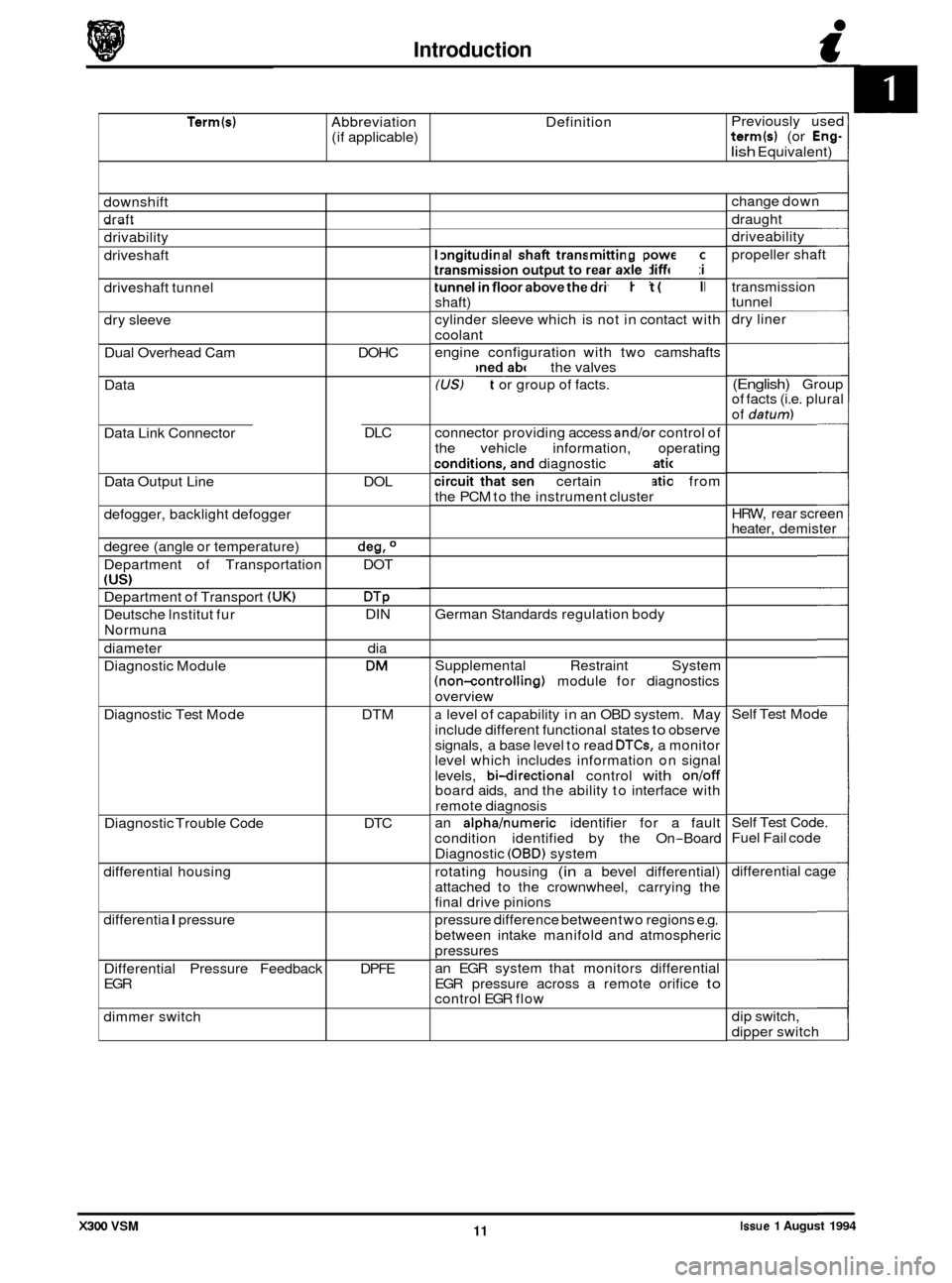
Term(s) Abbreviation Definition
(if applicable) Previously
used term(s) (or Eng-
lish Equivalent)
downshift
draft _.
drivability
driveshaft
driveshaft tunnel
dry sleeve
Dual Overhead Cam
Data
Data Link Connector
Data Output Line
defogger, backlight defogger
degree (angle or temperature)
Department of Transportation
(US)
Department of Transport (UK)
Deutsche lnstitut fur
Normuna
diameter
Diagnostic Module
Diagnostic Test Mode
Diagnostic Trouble Code
differential housing
differentia
I pressure
Differential Pressure Feedback
EGR
dimmer switch DOHC
DLC
DOL
deg, O
DOT
DTP DIN dia
DM
DTM
DTC
DPFE longitudinal
shaft transmitting power from
transmission output to rear axle differential
tunnel
in floor above the driveshaft (propeller
shaft)
cylinder sleeve which is not in contact with
coolant
engine configuration with two camshafts
positioned above the valves
(US) Fact or group of facts.
connector providing access
andlor control of
the vehicle information, operating
conditions, and diagnostic information
circuit that sends certain information from
the PCM to the instrument cluster
German Standards regulation body
Supplemental Restraint System
(non-controlling) module for diagnostics
overview
a level of capability in an OBD system. May
include different functional states
to observe
signals, a base level to read
DTCs, a monitor
level which includes information on signal
levels,
bi-directional control with onloff board aids, and the ability to interface with
remote diagnosis
an
alphahumeric identifier for a fault
condition identified by the On
-Board
Diagnostic
(OBD) system
rotating housing
(in a bevel differential)
attached to the crownwheel, carrying the
final drive pinions
pressure difference between two regions e.g.
between intake manifold and atmospheric
pressures
an EGR system that monitors differential
EGR pressure across a remote orifice
to control EGR flow change
down
draught
driveability
propeller shaft
transmission
tunnel
dry liner
(English) Group
of facts (i.e. plural
of
datum)
HRW, rear screen
heater, demister
Self Test Mode
Self Test Code.
Fuel Fail code
differential cage
dip switch,
dipper switch
Issue 1 August 1994 11 X300 VSM
Page 114 of 521
Manual Transmission & Clutch (AJ16)
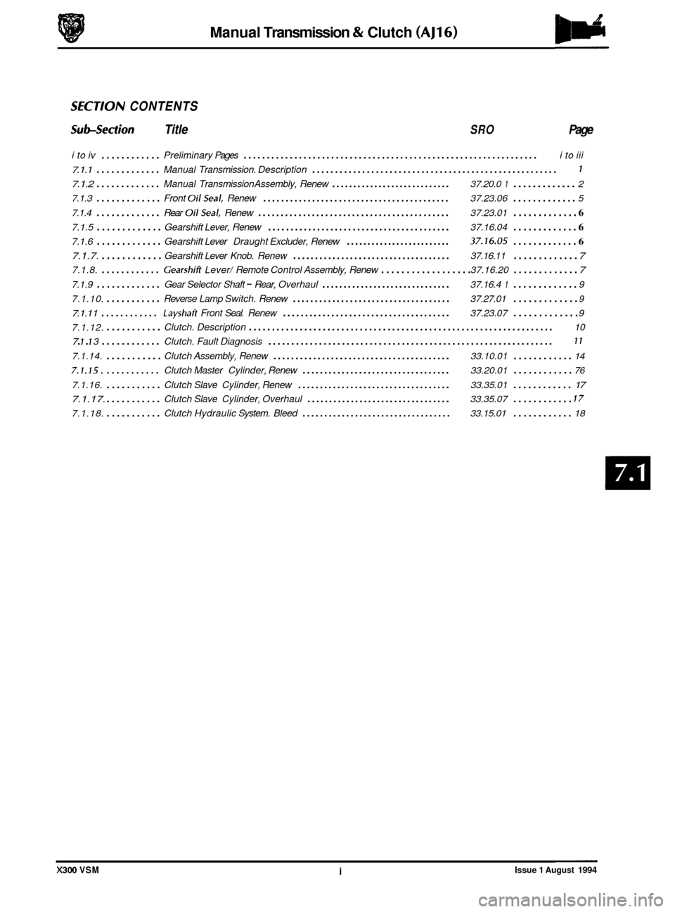
SECTlON CONTENTS
Sub-section Title SRO Page
i to iv ............ Preliminary Pages ................................................................ i to iii
7.1.1 ............. Manual Transmission. Description ...................................................... 1
7.1.2 ............. Manual Transmission Assembly, Renew ............................ 37.20.0 1 ............. 2
7.1.3
............. Front OilSeal. Renew .......................................... 37.23.06 ............. 5
7.1.4
............. Rear OilSeal. Renew ........................................... 37.23.01 ............. 6
7.1.5 ............. Gearshift Lever, Renew ......................................... 37.16.04 ............. 6
7.1.6 ............. Gearshift Lever Draught Excluder, Renew ......................... 37.16.05 ............. 6
7.1.7. ............ Gearshift Lever Knob. Renew .................................... 37.16.11 ............. 7
7.1.8. ............ Gearshifi Lever/ Remote Control Assembly, Renew .................. 37.16.20 ............. 7
7.1.9 ............. Gear Selector Shaft - Rear, Overhaul .............................. 37.16.4 1 ............. 9
7.1.10.
........... Reverse Lamp Switch. Renew .................................... 37.27.01 ............. 9
7.1.11 ............ Layshaft Front Seal. Renew ...................................... 37.23.07 ............. 9
7.1.12.
........... Clutch. Description .................................................................. 10
7.1.14.
........... Clutch Assembly, Renew ........................................ 33.10.01 ............ 14
7.1.15. ........... Clutch Master Cylinder, Renew .................................. 33.20.01 ............ 76
7.1.16. ........... Clutch Slave Cylinder, Renew ................................... 33.35.01 ............ 17
7.1.17.
........... Clutch Slave Cylinder, Overhaul ................................. 33.35.07 ............ 17
7.1.18. ........... Clutch Hydraulic System. Bleed .................................. 33.15.01 ............ 18
7 . 1 . 7 3 ............ Clutch. Fault Diagnosis .............................................................. 11
X300 VSM i Issue 1 August 1994
Page 119 of 521
Manual Transmission & Clutch (AJ16)
7.1.2 MANUAL TRANSMISSION ASSEMBLY, RENEW
SRO 37.20.01
. Disconnect the battery.
. Remove inlet manifold rear securing nuts.
. Remove injector harness mounting bracket.
. Fit lifting bracket 18G 1465 and secure with the nuts.
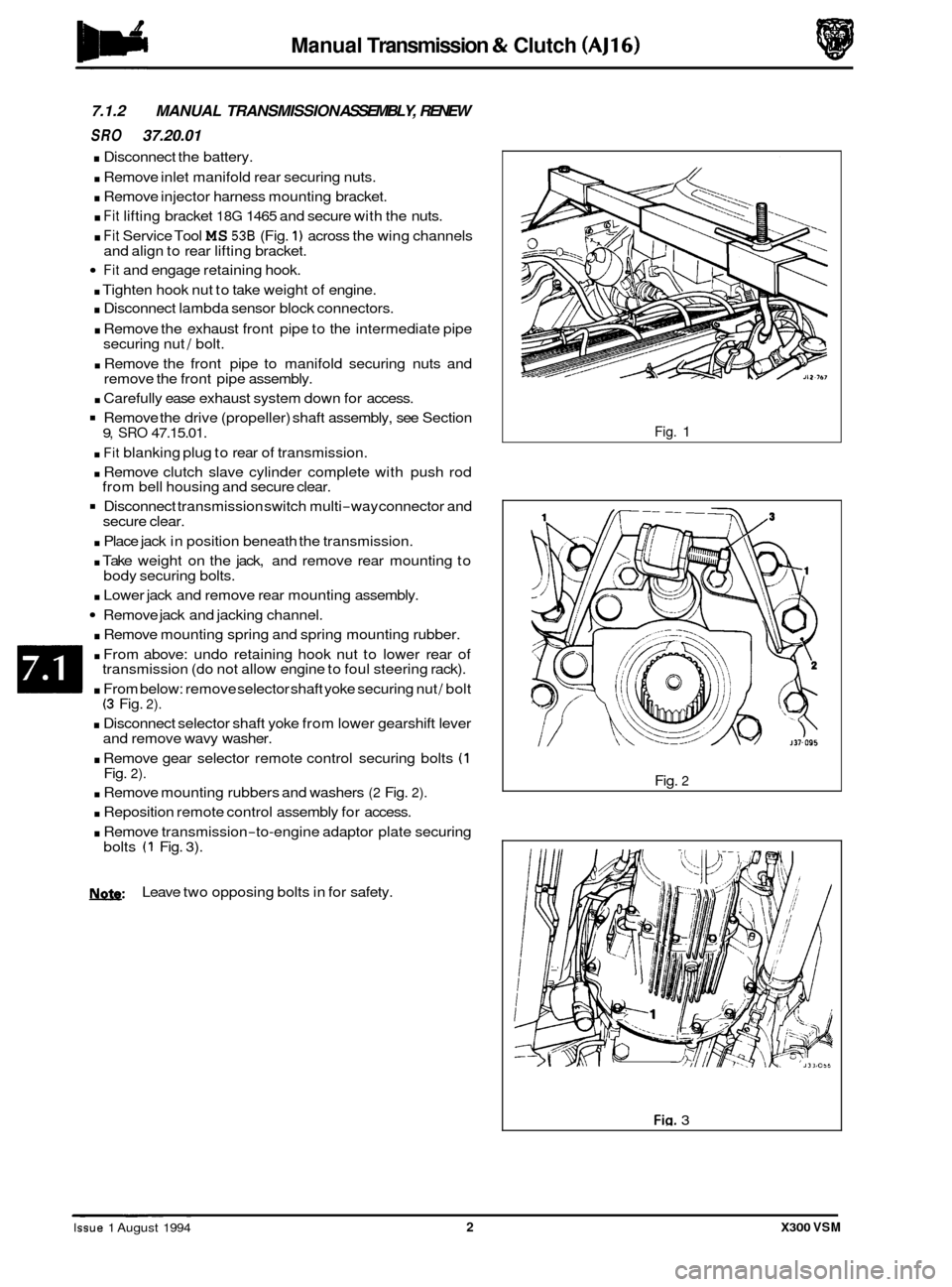
. Fit Service Tool MS 536 (Fig. 1) across the wing channels
Fit and engage retaining hook.
. Tighten hook nut to take weight of engine.
. Disconnect lambda sensor block connectors.
. Remove the exhaust front pipe to the intermediate pipe
securing nut / bolt.
. Remove the front pipe to manifold securing nuts and
remove the front pipe assembly.
. Carefully ease exhaust system down for access.
Remove the drive (propeller) shaft assembly, see Section
. Fit blanking plug to rear of transmission.
. Remove clutch slave cylinder complete with push rod
Disconnect transmission switch multi-way connector and
. Place jack in position beneath the transmission.
. Take weight on the jack, and remove rear mounting to
. Lower jack and remove rear mounting assembly.
Remove jack and jacking channel.
. Remove mounting spring and spring mounting rubber.
. From above: undo retaining hook nut to lower rear of
transmission (do not allow engine to foul steering rack).
. From below: remove selector shaft yoke securing nut / bolt (3 Fig. 2).
. Disconnect selector shaft yoke from lower gearshift lever
and remove wavy washer.
. Remove gear selector remote control securing bolts (1 Fig. 2).
. Remove mounting rubbers and washers (2 Fig. 2).
. Reposition remote control assembly for access.
. Remove transmission-to-engine adaptor plate securing
and
align to rear lifting bracket.
9, SRO 47.15.01.
from bell housing and secure clear.
secure clear.
body securing bolts.
bolts
(1 Fig. 3).
N.&: Leave two opposing bolts in for safety.
Fig. 1
Fig.
2
Fig. 3 ~ ~ ~~ ~
Issue 1 August 1994 2 X300 VSM
Page 121 of 521
Manual Transmission & clutch (AJ16)
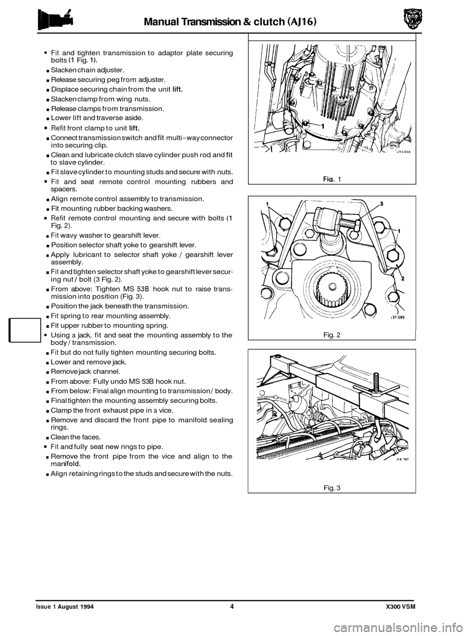
Fit and tighten transmission to adaptor plate securing
. Slacken chain adjuster.
. Release securing peg from adjuster.
. Displace securing chain from the unit lift.
. Slacken clamp from wing nuts.
. Release clamps from transmission.
. Lower lift and traverse aside.
Refit front clamp to unit lift.
. Connect transmission switch and fit multi-way connector
. Clean and lubricate clutch slave cylinder push rod and fit
. Fit slave cylinder to mounting studs and secure with nuts.
Fit and seat remote control mounting rubbers and
. Align remote control assembly to transmission.
. Fit mounting rubber backing washers.
Refit remote control mounting and secure with bolts (1
. Fit wavy washer to gearshift lever.
. Position selector shaft yoke to gearshift lever.
. Apply lubricant to selector shaft yoke / gearshift lever
. Fit and tighten selector shaft yoke to gearshift lever secur-
. From above: Tighten MS 538 hook nut to raise trans-
. Position the jack beneath the transmission.
bolts
(1 Fig. 1).
into
securing clip.
to slave cylinder.
spacers.
Fig.
2).
assembly.
ing nut
/ bolt (3 Fig. 2).
mission into position (Fig. 3).
. Fit spring to rear mounting assembly.
. Fit upper rubber to mounting spring.
Using a jack, fit and seat the mounting assembly to the body / transmission.
. Fit but do not fully tighten mounting securing bolts.
. Lower and remove jack.
. Remove jack channel.
. From above: Fully undo MS 53B hook nut.
. From below: Final align mounting to transmission / body.
. Final tighten the mounting assembly securing bolts.
. Clamp the front exhaust pipe in a vice.
. Remove and discard the front pipe to manifold sealing
. Clean the faces.
Fit and fully seat new rings to pipe.
. Remove the front pipe from the vice and align to the
. Align retaining rings to the studs and secure with the nuts.
rings.
man
ifold.
Fin. 1
Fig.
2
Fig. 3
Issue 1 August 1994 4 X300 VSM
Page 123 of 521
Manual Transmission & Clutch (AJ16)
7.1.4 REAR OIL SEAL, RENEW
SRO 37.23.01
Remove the drive (propeller) shaft, see Section 9, SRO
47.15.01.
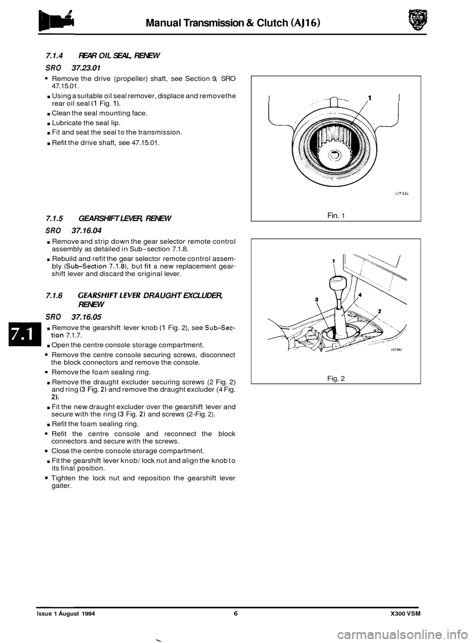
. Using a suitable oil seal remover, displace and removethe
rear oil seal (1 Fig. 1).
. Clean the seal mounting face.
. Lubricate the seal lip.
. Fit and seat the seal to the transmission.
. Refit the drive shaft, see 47.15.01.
7.1.5 GEARSHIFT LEVER, RENEW
SRO 37.16.04
. Remove and strip down the gear selector remote control
assembly as detailed in Sub-section 7.1.8.
. Rebuild and refit the gear selector remote control assem- bly (Sub-section 7.1.81, but fit a new replacement gear- shift lever and discard the original lever.
7.1.6 GEARSHIFTLEVER DRAUGHT EXCLUDER,
SRO 37.16.05 RENEW
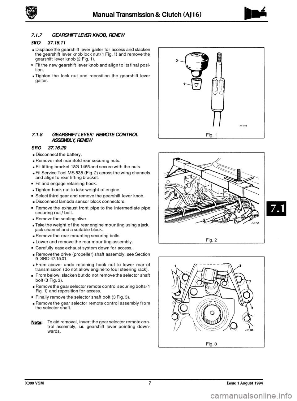
. Remove
the gearshift lever knob (1 Fig. 2), see Sub-Sec-
. Open the centre console storage compartment.
tion 7.1.7.
= Remove the centre console securing screws, disconnect
Remove the foam sealing ring.
. Remove the draught excluder securing screws (2 Fig. 2)
and ring (3 Fig. 2) and remove the draught excluder (4 Fig.
2).
. Fit the new draught excluder over the gearshift lever and
secure with the ring (3 Fig. 2) and screws (2-Fig. 2).
. Refit the foam sealing ring.
Refit the centre console and reconnect the block
Close the centre console storage compartment.
. Fit the gearshift lever knob/ lock nut and align the knob to
Tighten the lock nut and reposition the gearshift lever
the
block connectors and remove the console.
connectors and secure with the screws.
its final position.
gaiter.
I --0-. I
J37.02~
Fin. 1
Fig. 2
0
0
0
Issue 1 August 1994 6 X300 VSM
Page 124 of 521
Manual Transmission & Clutch (AJ16)
GEARSHIFT LEVER KNOB, RENEW
:RY 37.16.11
. Displace the gearshift lever gaiter for access and slacken
the gearshift lever knob lock nut (1 Fig. 1) and remove the
gearshift lever knob
(2 Fig. 1).
- Fit the new gearshift lever knob and align to its final posi- tion.
. Tighten the lock nut and reposition the gearshift lever
gaiter.
7.1.8 GEARSHIFT LEVER/ REMOTE CONTROL
ASSEMBLY, RENEW
SRO 37.16.20
. Disconnect the battery.
. Remove inlet manifold rear securing nuts.
. Fit lifting bracket 18G 1465 and secure with the nuts.
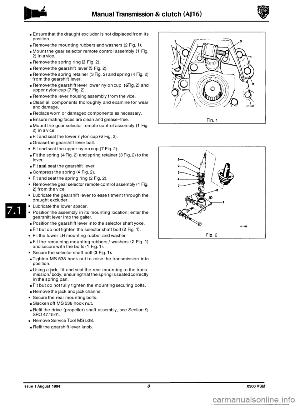
. Fit Service Tool MS 538 (Fig. 2) across the wing channels
and align to rear lifting bracket.
Fit and engage retaining hook.
. Tighten hook nut to take weight of engine.
Select third gear and remove the gearshift lever knob.
. Disconnect lambda sensor block connectors.
Remove the exhaust front pipe to the intermediate pipe
securing nut / bolt.
. Remove the sealing olive.
. Take the weight of the rear engine mounting using a jack,
. Remove the rear mounting securing bolts.
. Lower and remove the rear mounting assembly.
Carefully ease exhaust system down for access.
jack channel
and a suitable block.
. Remove the drive (propeller) shaft assembly, see Section 9, SRO 47.15.01.
. From above: undo retaining hook nut to lower rear of
transmission (do not allow engine to foul steering rack).
From below: slacken but do not remove the selector shaft
bolt
(3 Fig. 3).
. Remove the gear selector remote control securing bolts (1 Fig. 1) and reposition for access.
Finally remove the selector shaft bolt (3 Fig. 3).
. Remove the gear selector remote control assembly from
the selector shaft.
b: To aid removal, invert the gear selector remote con- trol assembly, i.e. gearshift lever pointing down- wards.
2
Fig. 1
Fig. 2
Fig. 3
X300 VSM 7 Issue 1 August 1994
Page 125 of 521
Manual Transmission & clutch (AJ16)
. Ensure that the draught excluder is not displaced from its
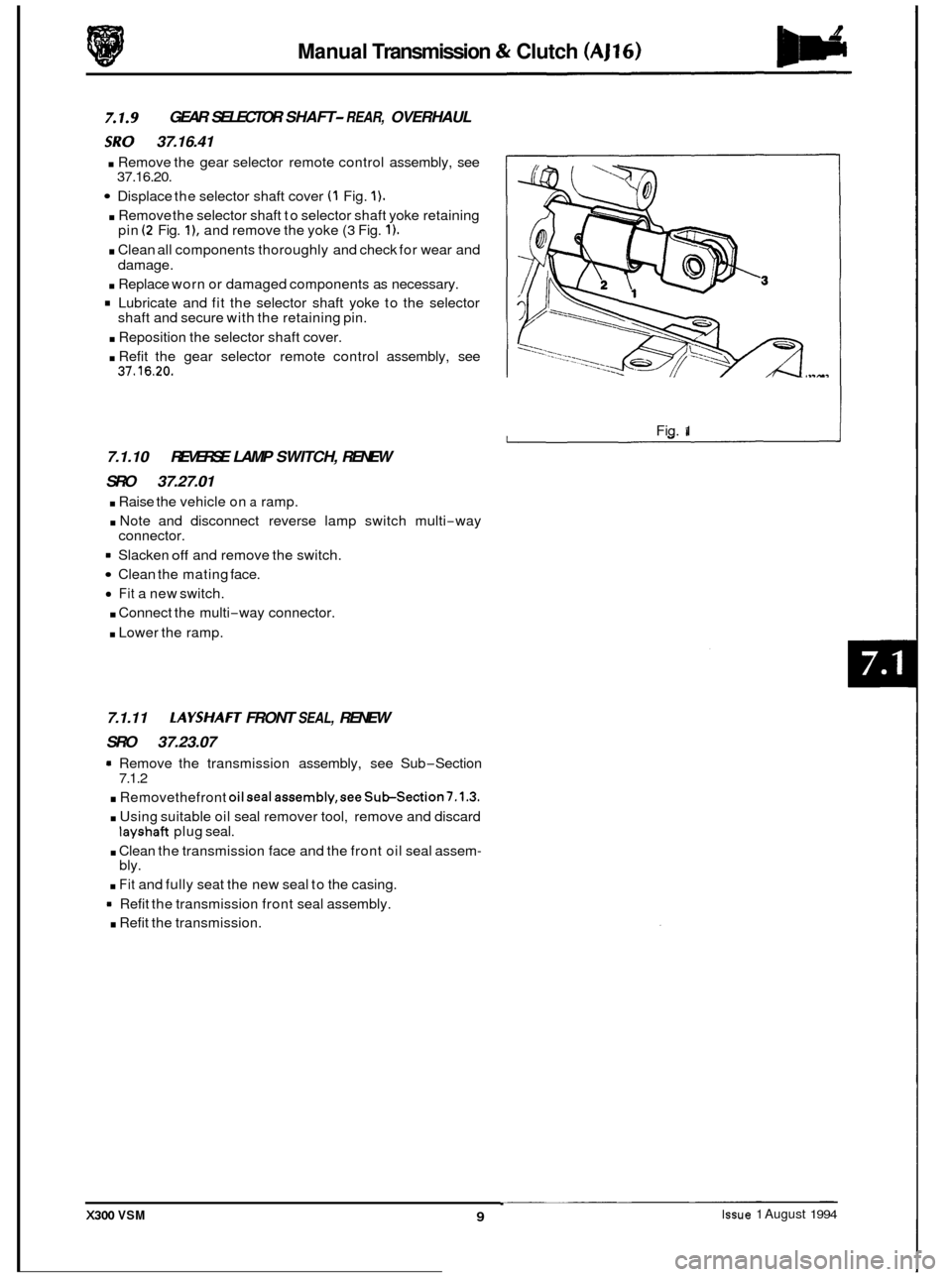
. Remove the mounting rubbers and washers (2 Fig. 1).
. Mount the gear selector remote control assembly (1 Fig.
. Remove the spring ring (2 Fig. 2).
. Remove the gearshift lever (5 Fig. 2).
. Remove the spring retainer (3 Fig. 2) and spring (4 Fig. 2)
. Remove the gearshift lever lower nylon cup (6 Fig. 2) and
. Remove the lever housing assembly from the vice.
. Clean all components thoroughly and examine for wear
. Replace worn or damaged components as necessary.
. Ensure mating faces are clean and grease-free.
. Mount the gear selector remote control assembly (1 Fig.
. Fit and seat the lower nylon cup (6 Fig. 2).
. Grease the gearshift lever ball.
Fit and seat the upper nylon cup (7 Fig. 2).
. Fit the spring (4 Fig. 2) and spring retainer (3 Fig. 2) to the
. Fit and seat the gearshift lever
. Compress the spring (4 Fig. 2).
* Fit and seat the spring ring (2 Fig. 2).
= Remove the gear selector remote control assembly (1 Fig.
Lubricate the gearshift lever to ease fitment through the
Lubricate the lower spacer.
Position the assembly in its mounting location; enter the
. Position the gearshift lever into the selector shaft yoke.
. Fit but do not tighten the selector shaft bolt (3 Fig. 1).
Fit the lower LH mounting rubber and washer.
. Fit the remaining mounting rubbers / washers (2 Fig. 1)
Secure the selector shaft bolt (3 Fig. 1).
. Tighten MS 538 hook nut to raise the transmission into
position.
. Using a jack, fit and seat the rear mounting to the trans- mission / body, ensuring that the spring is seated correctly
in the spring pan.
position.
2) in
a vice.
from the gearshift lever.
upper nylon cup (7
Fig. 2).
and damage.
2) in a vice.
lever.
2) from the vice.
draught excluder.
gearshift lever into the gaiter.
and secure with the bolts
(1 Fig. 1).
. Fit but do not fully tighten the mounting securing bolts.
. Remove the jack and jack channel.
Secure the rear mounting bolts.
. Slacken off MS 538 hook nut.
. Refit the drive (propeller) shaft assembly, see Section 9, SRO 47.15.01.
Remove Service Tool MS 538.
. Refit the gearshift lever knob.
Fin. 1
J37-WB
Fig. 2
Issue 1 August 1994 8 X300 VSM
Page 126 of 521
Manual Transmission & Clutch (AJ16)
GEAR SELECTOR SHAFT- REAR, OVERHAUL
iRY 37.16.41
. Remove the gear selector remote control assembly, see
Displace the selector shaft cover (1 Fig. 1).
. Remove the selector shaft to selector shaft yoke retaining
. Clean all components thoroughly and check for wear and
. Replace worn or damaged components as necessary.
Lubricate and fit the selector shaft yoke to the selector
. Reposition the selector shaft cover.
. Refit the gear selector remote control assembly, see
37.16.20.
pin
(2 Fig. I), and remove the yoke (3 Fig. 1).
damage.
shaft and secure with the retaining pin.
37.16.20.
7.1.10 REVERSE LAMP SWITCH, RENEW
SRO 37.27.01
. Raise the vehicle on a ramp.
. Note and disconnect reverse lamp switch multi-way
= Slacken off and remove the switch.
Clean the mating face.
Fit a new switch.
. Connect the multi-way connector.
. Lower the ramp.
connector.
7.1.11 LAYSHAFT FRONT SEAL, RENEW
SRO 37.23.07
a Remove the transmission assembly, see Sub-Section
. Removethefront oilseal assembly,seeSub-Section7.1.3.
. Using suitable oil seal remover tool, remove and discard
. Clean the transmission face and the front oil seal assem-
. Fit and fully seat the new seal to the casing.
= Refit the transmission front seal assembly.
. Refit the transmission.
7.1.2
layshaft plug
seal.
bly. Fig.
1
X300 VSM Issue 1 August 1994 9
Page 131 of 521
Manual Transmission & Clutch (AJ16) IBh
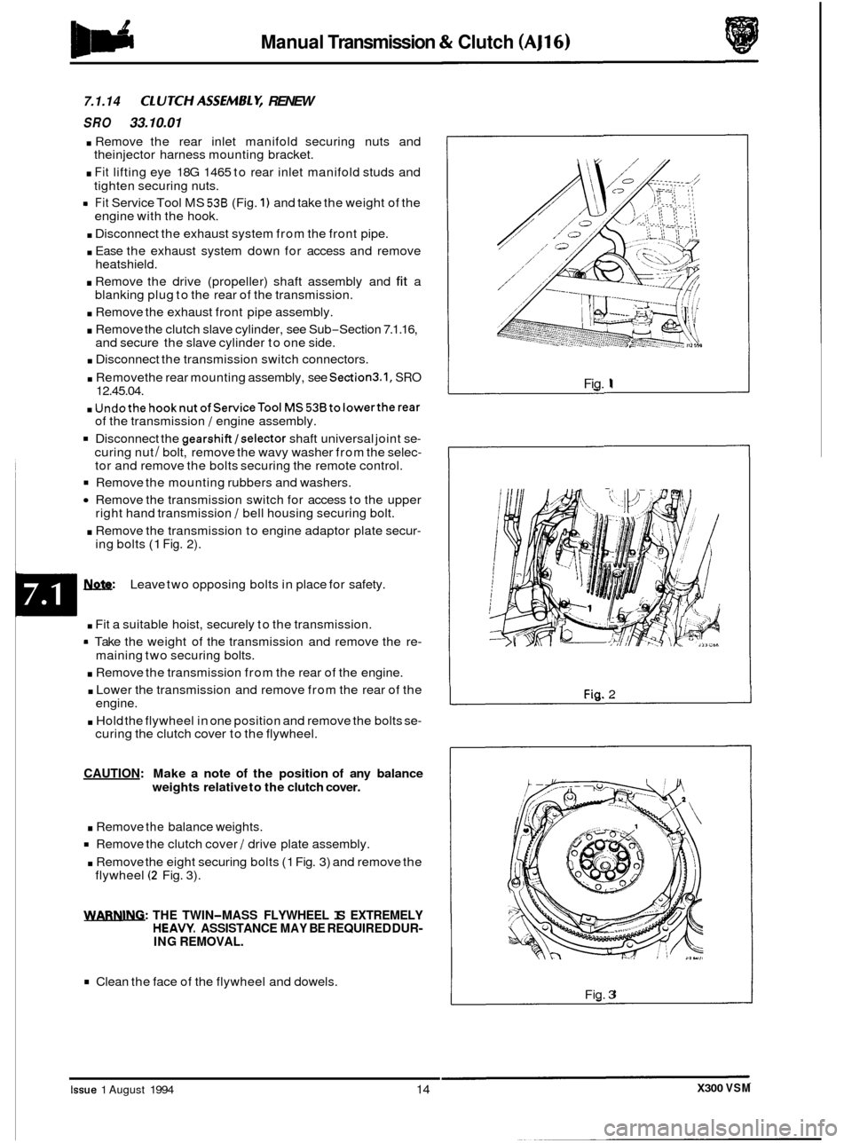
7.1.14 ClUTCHASSEMBLY, RENEW
SRO 33.10.01
. Remove the rear inlet manifold securing nuts and
. Fit lifting eye 18G 1465 to rear inlet manifold studs and
rn Fit Service Tool MS 538 (Fig. 1) and take the weight of the
. Disconnect the exhaust system from the front pipe.
. Ease the exhaust system down for access and remove
. Remove the drive (propeller) shaft assembly and fit a
. Remove the exhaust front pipe assembly.
. Remove the clutch slave cylinder, see Sub-Section 7.1.16,
and secure the slave cylinder to one side.
. Disconnect the transmission switch connectors.
. Removethe rear mounting assembly, see Section3.1, SRO 12.45.04.
. Undothe hooknutofServiceTool MS53Btolowertherear of the transmission / engine assembly.
Disconnect the gearshift/selector shaft universal joint se-
curing nut / bolt, remove the wavy washer from the selec- tor and remove the bolts securing the remote control.
Remove the mounting rubbers and washers.
Remove the transmission switch for access to the upper
. Remove the transmission to engine adaptor plate secur-
theinjector harness mounting bracket.
tighten securing nuts.
engine with the hook.
heatshield.
blanking plug to the rear of the transmission.
right hand transmission
/ bell housing securing bolt.
ing bolts
(1 Fig. 2).
Leave two opposing bolts in place for safety.
m . Fit a suitable hoist, securely to the transmission.
= Take the weight of the transmission and remove the re-
. Remove the transmission from the rear of the engine.
. Lower the transmission and remove from the rear of the
. Hold the flywheel in one position and remove the bolts se-
maining two securing bolts.
engine.
curing the clutch cover to the flywheel.
CAUTION: Make a note of the position of any balance
weights relative to the clutch cover.
. Remove the balance weights.
Remove the clutch cover / drive plate assembly.
. Remove the eight securing bolts (1 Fig. 3) and remove the
flywheel (2 Fig. 3).
WARNING: THE TWIN-MASS FLYWHEEL IS EXTREMELY HEAVY. ASSISTANCE MAY BE REQUIRED DUR- ING REMOVAL.
Clean the face of the flywheel and dowels.
Fig. 1
Fig. 2
Fig. 3
X300 VSM Issue 1 August 1994 14
Page 201 of 521
@ Steering
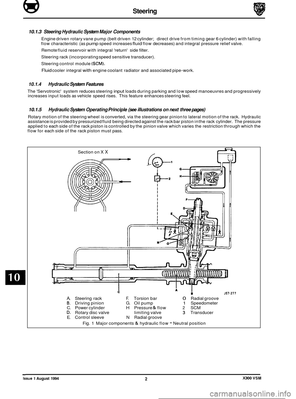
10.1.3 Steering Hydraulic System Major Components
Engine driven rotary vane pump (belt driven 12 cylinder; direct drive from timing gear 6 cylinder) with falling
flow characteristic (as
pump speed increases fluid flow decreases) and integral pressure relief valve.
Remote fluid reservoir with integral 'return' side filter.
Steering rack (incorporating speed sensitive transducer).
Steering control module
(SCM).
Fluid cooler integral with engine coolant radiator and associated pipe-work.
10.1.4 Hydraulic System Features
The 'Servotronic' system reduces steering input loads during parking and low speed manoeuvres and progressively
increases input loads as vehicle speed rises. This feature enhances steering feel.
10.1.5
Rotary motion of the steering wheel is converted, via the steering gear pinion to lateral motion of the rack. Hydraulic
assistance is provided by pressurized fluid being directed against the rack bar piston in the rack cylinder. The pressure
applied to each side of the rack piston is controlled by the pinion valve which varies the restriction through which the
flow for each side of the rack piston must pass.
Hydraulic System Operating Principle (see illustrations on next three pages)
Section on X X
J57-277
A. Steering rack F. Torsion bar 0 Radial groove B. Driving pinion G. Oil pump 1 Speedometer
C. Power cylinder H Pressure & flow 2 SCM D. Rotary disc valve limiting valve 3 Transducer
E. Control sleeve N Radial groove
Fig.
1 Major components & hydraulic flow - Neutral position ~
Issue 1 August 1994 X300 VSM 2