set clock JAGUAR XJ6 1994 2.G Workshop Manual
[x] Cancel search | Manufacturer: JAGUAR, Model Year: 1994, Model line: XJ6, Model: JAGUAR XJ6 1994 2.GPages: 521, PDF Size: 17.35 MB
Page 69 of 521

€3 Cooling System (V12)
4.2.4 DRAIN AND FILL PROCEDURES
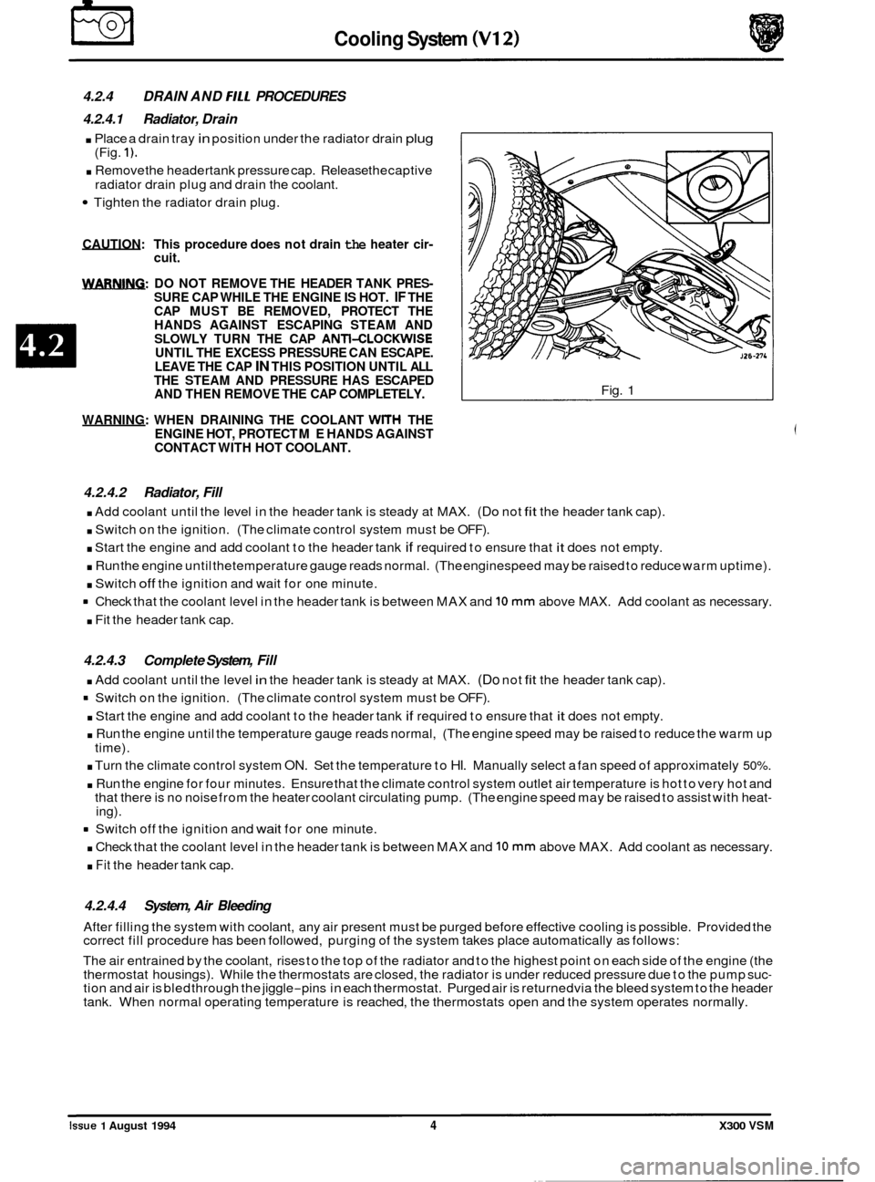
4.2.4.1 Radiator, Drain
. Place a drain tray in position under the radiator drain plug
. Remove the headertank pressure cap. Release thecaptive
Tighten the radiator drain plug.
(Fig.
1).
radiator drain
plug and drain the coolant.
CAUTION: This procedure does not drain the heater cir- cuit.
m: DO NOT REMOVE THE HEADER TANK PRES- SURE CAP WHILE THE ENGINE IS HOT. IF THE
CAP MUST BE REMOVED, PROTECT THE
HANDS AGAINST ESCAPING STEAM AND
SLOWLY TURN THE CAP
ANTI-CLOCKWISE UNTIL THE EXCESS PRESSURE CAN ESCAPE.
LEAVE THE CAP IN THIS POSITION UNTIL ALL
THE STEAM AND PRESSURE HAS ESCAPED
AND THEN REMOVE THE CAP COMPLETELY.
WARNING: WHEN DRAINING THE COOLANT
WITH THE
ENGINE HOT, PROTECT ME HANDS AGAINST
CONTACT WITH HOT COOLANT.
Fig. 1
4.2.4.2 Radiator, Fill
. Add coolant until the level in the header tank is steady at MAX. (Do not fit the header tank cap).
. Switch on the ignition. (The climate control system must be OFF).
. Start the engine and add coolant to the header tank if required to ensure that it does not empty.
. Run the engine until thetemperature gauge reads normal. (The enginespeed may be raised to reduce warm uptime).
. Switch off the ignition and wait for one minute.
Check that the coolant level in the header tank is between MAX and
10 mm above MAX. Add coolant as necessary.
. Fit the header tank cap.
4.2.4.3 Complete System, Fill
. Add coolant until the level in the header tank is steady at MAX. (Do not fit the header tank cap).
= Switch on the ignition. (The climate control system must be OFF).
. Start the engine and add coolant to the header tank if required to ensure that it does not empty.
. Run the engine until the temperature gauge reads normal, (The engine speed may be raised to reduce the warm up
. Turn the climate control system ON. Set the temperature to HI. Manually select a fan speed of approximately 50%.
. Run the engine for four minutes. Ensure that the climate control system outlet air temperature is hot to very hot and
that there is no noise from the heater coolant circulating pump. (The engine speed may be raised to assist with heat- ing).
time).
8 Switch
off the ignition and wait for one minute.
. Check that the coolant level in the header tank is between MAX and 10 mm above MAX. Add coolant as necessary.
. Fit the header tank cap.
4.2.4.4 System, Air Bleeding
After filling the system with coolant, any air present must be purged before effective cooling is possible. Provided the
correct fill procedure has been followed, purging of the system takes place automatically as follows:
The air entrained by the coolant, rises to the top of the radiator and to the highest point on each side of the engine (the
thermostat housings). While the thermostats are closed, the radiator is under reduced pressure due to the pump suc
- tion and air is bled through the jiggle-pins in each thermostat. Purged air is returnedvia the bleed system to the header
tank. When normal operating temperature is reached, the thermostats open and the system operates normally. ~~
Issue 1 August 1994 4 X300 VSM
Page 332 of 521

Climate Control Systems
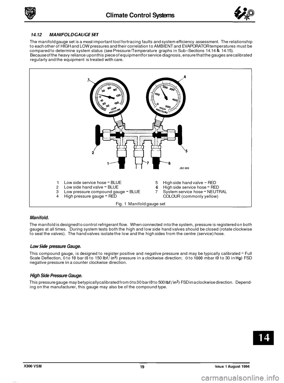
14.12 MANIFOLD GAUGESET
The manifold gauge set is a most important tool fortracing faults and system efficiency assessment. The relationship
to each other of HIGH and LOW pressures and their correlation to AMBIENT and EVAPORATOR temperatures must be
compared to determine system status (see Pressure /Temperature graphs in Sub
-Sections 14.14 & 14.15).
Because of the heavy reliance upon this piece of equipmentfor service diagnosis, ensure that the gauges are calibrated
regularly and the equipment is treated
with care.
3
1 Low side service hose - BLUE
5 High side hand valve - RED 2 Low side hand valve - BLUE 6 High side service hose - RED
3 Low pressure compound gauge - BLUE 7 System service hose - NEUTRAL
4 High pressure gauge - RED
COLOUR (commonly yellow)
Fig. 1 Manifold gauge set
Manifold.
The manifold is designed to control refrigerant flow. When connected into the system, pressure is registered on both
gauges at all times. During system tests both the high and low side hand valves should be closed (rotate clockwise
to seat the valves). The hand valves isolate the low and the high sides from the centre (service) hose.
0 Low side pressure Gauge.
This compound gauge, is designed to register positive and negative pressure and may be typically calibrated - Full
Scale Deflection, 0 to 10 bar (0 to 150 Ibf / in2) pressure in a clockwise direction; 0 to 1000 mbar (0 to 30 in Hg) FSD
negative pressure in a counter clockwise direction.
High Side Pressure Gauge.
This pressure gauge may betypicallycalibrated from 0 to30 bar (0 to 500 Ibf/in2) FSD in a clockwise direction. Depend-
ing on the manufacturer, this gauge may also be of the compound type.
X300 VSM Issue 1 August 1994
Page 345 of 521

rl Electrical
15.1.6 Fire Hazard Infonnath
Thermal decomposition or combustion may produce dense smoke and other dangerous fumes which in fire situations
form
a highly toxic explosive.
In the event of fire the surrounding area must be evacuated and
all personnel kept well upwind of the area.
Full fire fighting protective gear and
a self contained breathing apparatus operating in the positive pressure mode must
be worn for combating fire. Material near fires must be cooled with water spray to prevent ignition.
Fires should be allowed to burn themselves
out if not threatening to life or property. If fire is threatening to life or prop- erty use copious quantities of water to extinguish.
15.1.7 Ventilath
Local exhaust ventilation designed by a professional engineer should be provided if vapours, fumes, or dusts are gen- erated whilst working with airbag module.
The latest issue of the manual for recommended practices on 'Industrial Ventilation' is available from the
ACGIH Com- mittee on Industrial Ventilation, PO Box 16153, Lansing, MI 48910, USA.
The need for local exhaust ventilation should be evaluated by a professional industrial hygienist.
15.1.8 Respiratory Precauth
To prevent the inhalation of dangerous fumes and dusts, an approved mask should be worn.
15.1.9 Eye Protection
Chemical protective goggles are recommended where there is a possibility of eye contact with the propellant.
Safety glasses with side shields are recommended for
all other operations.
15.1. I0 Protective Clothing
Approved protective gloves, overalls and shoes / boots should be worn.
15.1.1 1 Handling and Storage Precautions
Do not store airbag module near live electrical equipment or circuitry. Store in a dry environment at ambient tempera-
tures.
Good housekeeping and engineering practices should be employed to prevent the generation and accumulation of
dusts. Store in compliance with
all local state and federal regulations.
15.1.12 Driver And Passenger Airbag Modules Assembly / Removal / Service Instructions
Before starting work, ensure ignition switch is in 'IocK position, key is removed and negative terminal cable
is disconnected from the battery.
As the airbag is equipped with a back up power source and due to the risk of airbag being inadvertently
deployed, wait one minute or longer before starting work.
0 Disconnecting the battery cancels the memory for clock, radio, seats, mirrors, steering column and any other
components using battery power. Reset memory after work is completed.
0 Never use airbags from other vehicles, always use new parts.
0 After work is completed, reconnect battery and perform warning light check see diagnostic manual.
0 Never use electrical probes to check voltage or electrical resistance.
0 Disconnect the airbag before carrying out any work on, or in the vicinity of module, or when using electric weld- ing equipment.
0 Always ensure that battery negative has been disconnected for one minute or longer before commencing any
removal procedure.
EB
Issue 1 August 1994 4 X300 VSM
Page 393 of 521

Tire Replacement And Wheel hterchanging
WARNING: UNDER NO CIRCUMSTANCES SHOULD CROSS-PLY TIRES BE FITTED.
When renewal of tires is necessary, it is preferable to fit a complete set.
Should eitherfront or reartires only (i.e.
notthe full set) show a necessityfor renewal, newtires must befitted to replace
the worn ones.
No attempt must be made to interchange tires from the front to the rear orvice-versa, as wear produces a characteristic
pattern on each tire depending upon its position on the vehicle. If this position is changed after wear has occurred, the
performance of the tire will be adversely affected.
It should be remembered that new tires must be balanced.
The radial ply tires specified here are designed to meet the high speed performance of this vehicle. Only tires of ident
- ical specification as shown in this section must be fitted as replacements. If two replacement tires are fitted to one axle,
they must be of the same type and pattern as those on the other axle, i.e. tires must be used in sets of four of the same
manufacturer and tread pattern,
not intermixed.
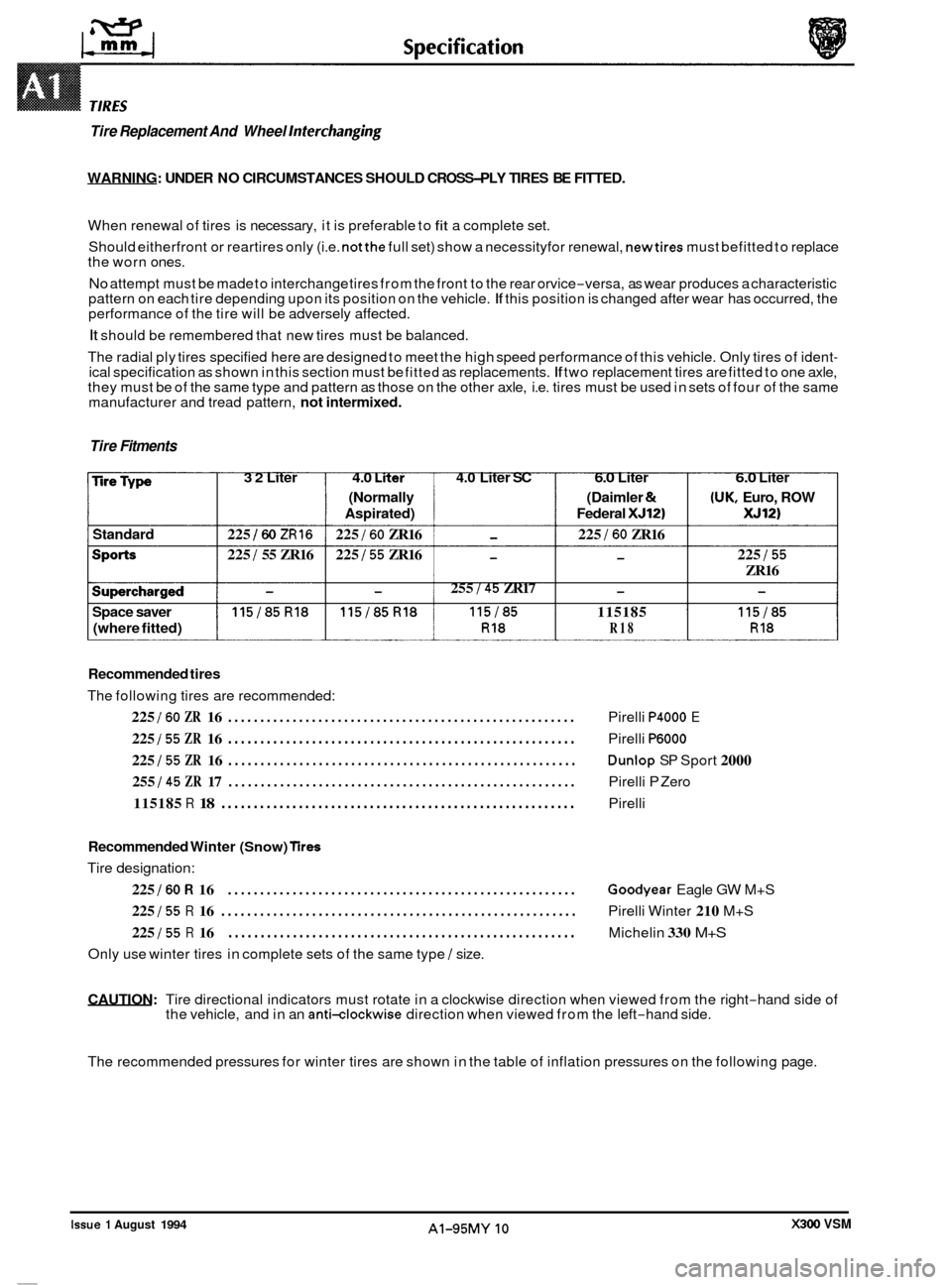
Tire Fitments
32 Liter 4.0 Liier 4.0 Liter SC 6.0 Liter 6.0 Liter 0
(Normally (Daimler & (UK, Euro, ROW
Aspirated) Federal
XJ12) XJ12)
Standard 225 160 ZR16 225 I60 ZR16 - 225 I60 ZR16
225
1 55 ZR16 225 I55 ZR16 - - 225 I55
ZR16
- 255 I45 ZR17 - -
Space saver 115/85R18 115/85R18 115185 115185 115185
(where fitted) RI8 R18 RI8
Recommended tires
The following tires are recommended:
225 I60 ZR 16 ...................................................... Pirelli P4000 E
225 155 ZR 16 ...................................................... Pirelli P6000
225 155 ZR 16 ...................................................... Dunlop SP Sport 2000
255
145 ZR 17 ...................................................... Pirelli P Zero
115185 R 18 Pirelli .......................................................
0
Recommended Winter (Snow) Tires
Tire designation:
225 I60 R 16 ...................................................... Goodyear Eagle GW M+S
225 155 R 16 ....................................................... Pirelli Winter 210 M+S
225 I55 R 16 ...................................................... Michelin 330 M+S
Only use winter tires in complete sets of the same type I size.
CAUTION: Tire directional indicators must rotate in a clockwise direction when viewed from the right-hand side of
the vehicle, and in an anti-clockwise direction when viewed from the left-hand side.
The recommended pressures for winter tires are shown in the table of inflation pressures on the following page.
0
X300 VSM Issue 1 August 1994 AI-95MY 10