height adjustment JAGUAR XJ6 1994 2.G Workshop Manual
[x] Cancel search | Manufacturer: JAGUAR, Model Year: 1994, Model line: XJ6, Model: JAGUAR XJ6 1994 2.GPages: 521, PDF Size: 17.35 MB
Page 200 of 521

10.1 STEERING SYSTEM DESCRIPTION
10.1.1 Steering Column Major Components
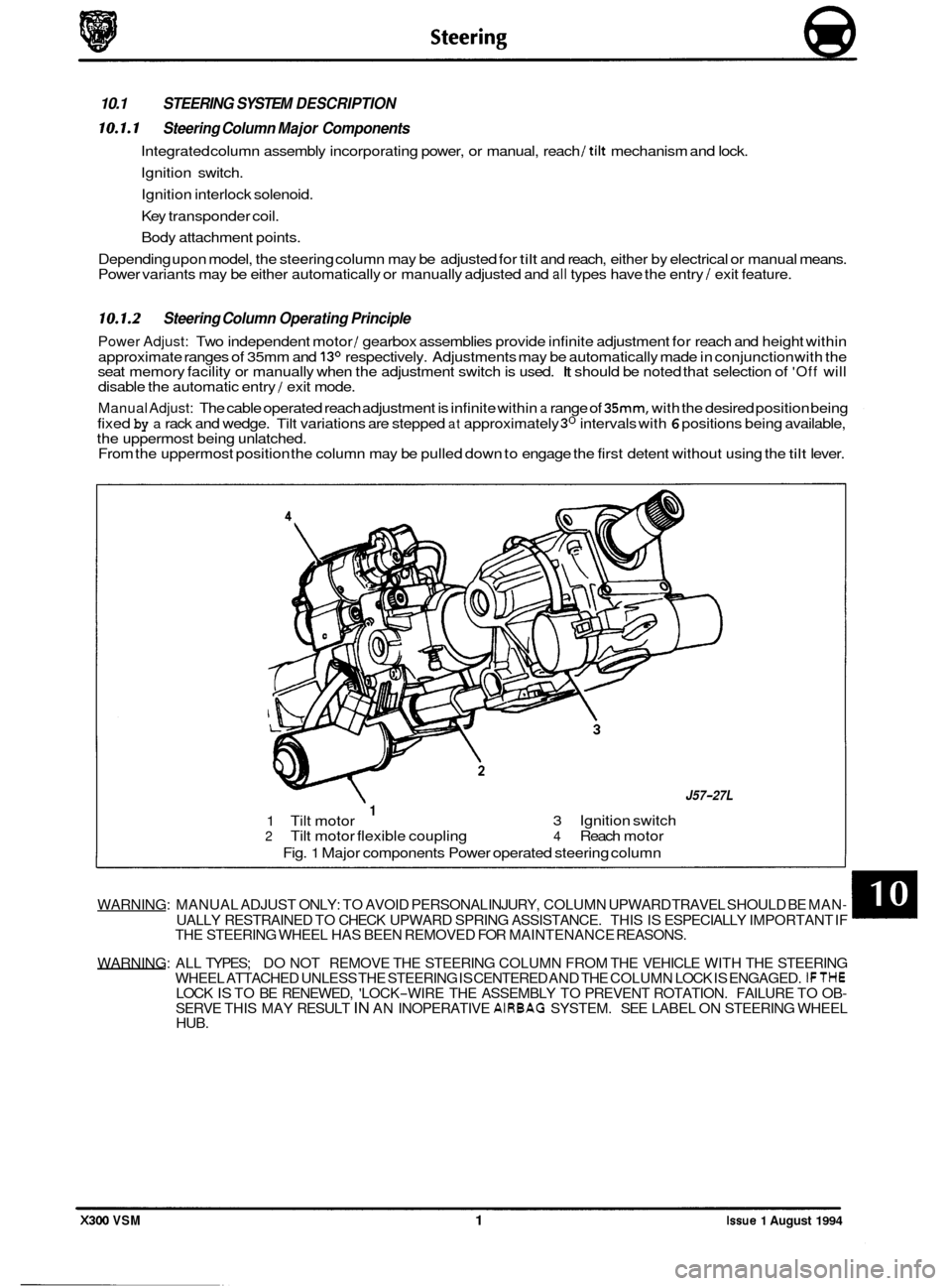
Integrated column assembly incorporating power, or manual, reach /tilt mechanism and lock.
Ignition switch.
Ignition interlock solenoid.
Key transponder coil.
Body attachment points.
Depending upon model, the steering column may be adjusted for
tilt and reach, either by electrical or manual means.
Power variants may be either automatically or manually adjusted and all types have the entry / exit feature.
10.1.2 Steering Column Operating Principle
Power Adjust: Two independent motor / gearbox assemblies provide infinite adjustment for reach and height within
approximate ranges of 35mm and
13O respectively. Adjustments may be automatically made in conjunction with the
seat memory facility or manually when the adjustment switch is used. It should be noted that selection of 'Off will
disable the automatic entry / exit mode.
Manual Adjust: The cable operated reach adjustment is infinite within a range of 35mm, with the desired position being
fixed
by a rack and wedge. Tilt variations are stepped at approximately 3O intervals with 6 positions being available,
the uppermost being unlatched.
From the uppermost position the column may be pulled down to engage the first detent without using the
tilt lever.
WARNING: MANUAL ADJUST ONLY: TO AVOID PERSONAL INJURY, COLUMN UPWARD TRAVEL SHOULD BE MAN- UALLY RESTRAINED TO CHECK UPWARD SPRING ASSISTANCE. THIS IS ESPECIALLY IMPORTANT IF
THE STEERING WHEEL HAS BEEN REMOVED FOR MAINTENANCE REASONS.
WARNING: ALL TYPES; DO NOT REMOVE THE STEERING COLUMN FROM THE VEHICLE WITH THE STEERING
WHEEL ATTACHED UNLESS THE STEERING
IS CENTERED AND THE COLUMN LOCK IS ENGAGED. IFTHE
SERVE THIS MAY RESULT IN AN INOPERATIVE AIRBAG SYSTEM. SEE LABEL ON STEERING WHEEL
HUB. LOCK IS TO BE RENEWED, 'LOCK-WIRE THE ASSEMBLY TO PREVENT ROTATION. FAILURE TO OB-
0
X300 VSM 1 Issue 1 August 1994
J57-27L
3 Ignition switch 1 1 Tilt motor 2 Tilt motor flexible coupling 4 Reach motor
Fig.
1 Major components Power operated steering column
Page 303 of 521

Body Components & Trim a
13.8 SEATING AND SEAT BELTS
13.8.1 Seating, Description
The front seats are available in a range of materials consisting of sculptured fabric / leather, leather, sports cloth / leather, embossed leather / leather and autolux. Both seats are available as 'manual', ie manually adjustable with elec- tric rise and fall, manual height adjustment headrests, 'power', ie 12-way electric adjustment, 'power with memory', ie memory controlled, 12-way electric adjustment of seat, steering column and exterior rear view mirrors and 'heated',
ie with integral heating.
Front seats are based on a non
-handed, one-piece frame which includes cushion and squab frames and seat adjuster
mechanisms. The seat switchpacks (powerseats) are fitted to the outboard side of driver and passenger seats; on 'man- ual'seats, the seat height adjustment switch is similarly located. Seat control modules SCMs are contained within the
seat assemblies. The seats are secured through four mounting points to the vehicle floor.
Rear seats are of the bench type with
full width removable cushion and individual seat squabs.
Electrical components installed on the heel board below the rear passenger seat are protected
by two covers secured
by two locating brackets on the floor and by two latches on the cover. The latches are released by pushing down on
the two recesses in the top edge of the cover.
13.8.2 Front Manual Seat, Renew
. Disconnect vehicle battery ground lead.
. Disconnect electrical connections as required.
. Remove the seat forward fixings.
Move the seat fully forward.
. Remove the rear fixing / slide covers.
. Remove the seat rear fixings.
. Reposition seat for access and remove seat from vehicle.
. To refit seat, carry out reversal of above procedure.
13.8.3
. Disconnect vehicle battery ground lead.
. Move the seat fully forward to gain access to squab back
Remove squab side fixings, disconnect lamp harness and
. To refit, carry out reversal of the above procedure.
Front Seat (Power Operated) Squab Back
Cover, Renew
cover outer fixings.
remove squab back cover.
13.8.4
. Position seat as required for access.
. Disconnect vehicle battery ground lead.
. Release sound insulation retainers and displace insula-
. Remove SCM cover, move SCM aside and remove seat
. Remove the seat forward fixings and move the seat fully
. Remove the seat rearward fixing covers and remove the
. Disconnect multi-plugs, seat switch and motor harness to
. Release harness tie strap and remove seat assembly from
Front Seat (Power Operated), Renew
tion.
switch
multi-plug from its mounting bracket.
forward. seat rearward fixings.
SCM.
vehicle.
. To refit, carry out reversal of the above procedure, ensur- ing that fixings are tightened to the correct torque.
Issue 1 August 1994 48 X300 VSM
0
0
0
Page 464 of 521

conditions.
. Tighten all fixings to specification.
A4.6.1.3 SERVICE PROCEDURES
A4.6.1.4
Fitted Condition (Front)
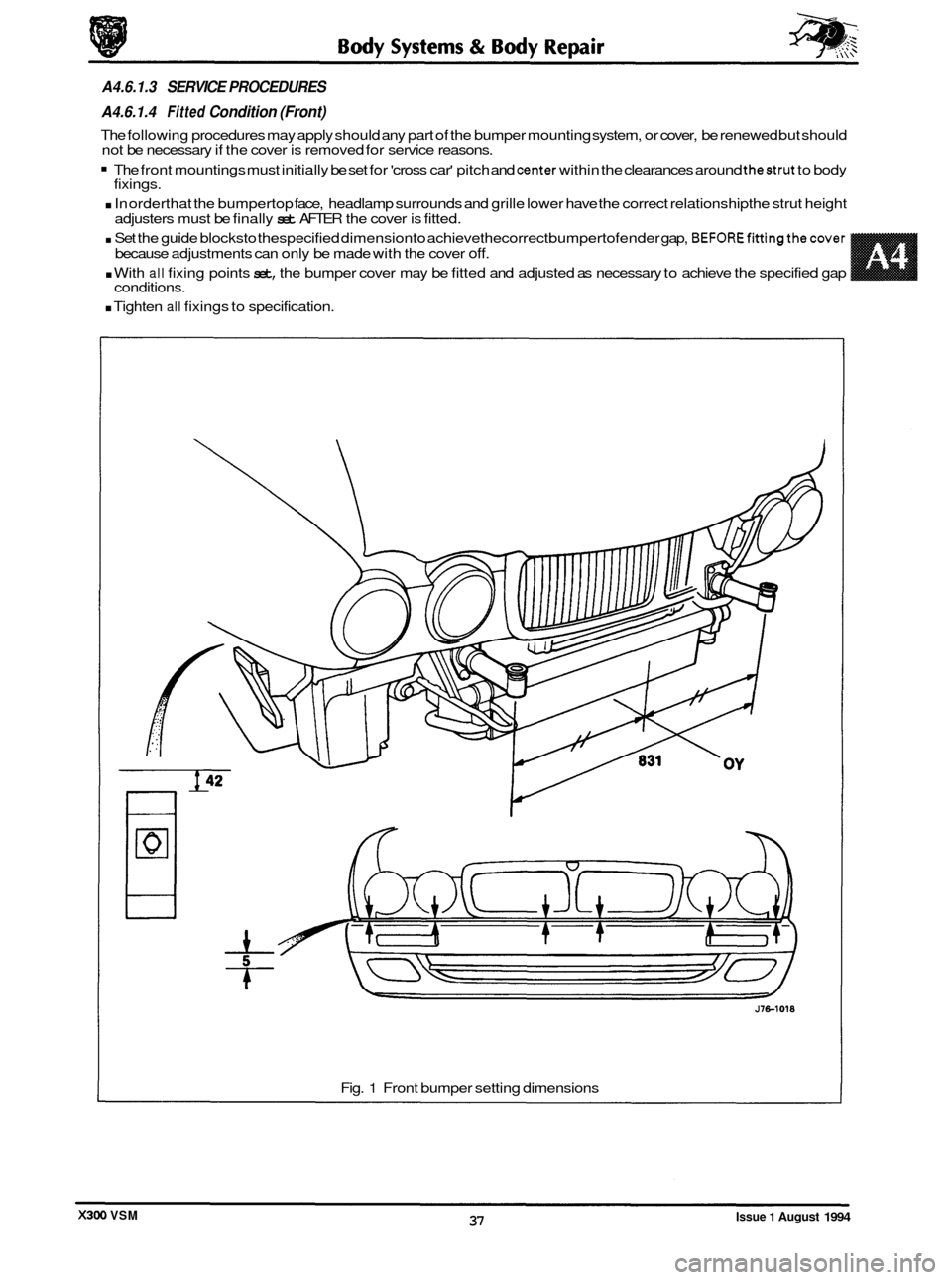
The following procedures may apply should any part of the bumper mounting system, or cover, be renewed but should
not be necessary if the cover is removed for service reasons.
The front mountings must initially be set for 'cross car' pitch and center within the clearances around thestrut to body
. In orderthat the bumpertop face, headlamp surrounds and grille lower have the correct relationship the strut height
. Set the guide blocksto thespecified dimensionto achievethecorrect bumpertofender gap, BEFOREfittingthecover
. With all fixing points set, the bumper cover may be fitted and adjusted as necessary to achieve the specified gap
fixings.
adjusters must be finally
set AFTER the cover is fitted.
because adjustments can only be made with the cover
off.
Fig. 1 Front bumper setting dimensions
Issue 1 August 1994 37 X300 VSM