Chapter 12 JAGUAR XJ6 1997 2.G Workshop Manual
[x] Cancel search | Manufacturer: JAGUAR, Model Year: 1997, Model line: XJ6, Model: JAGUAR XJ6 1997 2.GPages: 227, PDF Size: 7.2 MB
Page 173 of 227
8Adjustment should be made with the
vehicle parked 25 feet from the wall, sitting
level, the petrol tank half-full and no unusually
heavy load in the vehicle.
9Starting with the low beam adjustment,
position the high intensity zone so it is two
inches below the horizontal line and two
inches to the right of the headlight vertical
line. Adjustments are made by turning the
knobs located behind the headlight housings
(see illustration 18.2).
10With the high beams on, the high intensity
zone should be vertically centred with the
exact centre just below the horizontal line.
Note:It may not be possible to position the
headlight aim exactly for both high and low
beams. If a compromise must be made, keep
in mind that the low beams are the most used
and have the greatest effect on safety.
11Have the headlights adjusted by a dealer
service department or service station at the
earliest opportunity.
19 Headlight housing
(1992 to 1994 models)-
removal and refitting
1
Warning: These vehicles are
equipped with halogen gas-filled
headlight bulbs which are under
pressure and may shatter if the
surface is damaged or the bulb is dropped.
Wear eye protection and handle the bulbs
carefully, grasping only the base whenever
possible. Do not touch the surface of the
bulb with your fingers because the oil from
your skin could cause it to overheat and
fail prematurely. If you do touch the bulb
surface, clean it with rubbing alcohol.
1Remove the headlight bulb (Section 17).
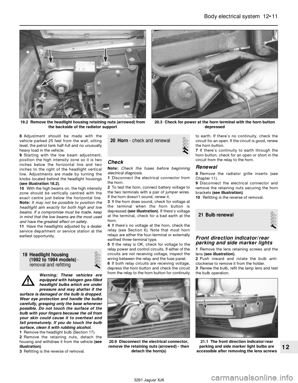
2Remove the retaining nuts, detach the
housing and withdraw it from the vehicle (see
illustration).
3Refitting is the reverse of removal.
20 Horn- check and renewal
2
Check
Note:Check the fuses before beginning
electrical diagnosis.
1Disconnect the electrical connector from
the horn.
2To test the horn, connect battery voltage to
the two terminals with a pair of jumper wires.
If the horn doesn’t sound, renew it.
3If the horn does sound, check for voltage at
the terminal when the horn button is
depressed (see illustration). If there’s voltage
at the terminal, check for a bad earth at the
horn.
4If there’s no voltage at the horn, check the
relay (see Section 6). Note that most horn
relays are either the four-terminal or externally
earthed three-terminal type.
5If the relay is OK, check for voltage to the
relay power and control circuits. If either of the
circuits are not receiving voltage, inspect the
wiring between the relay and the fuse panel.
6If both relay circuits are receiving voltage,
depress the horn button and check the circuit
from the relay to the horn button for continuityto earth. If there’s no continuity, check the
circuit for an open. If the circuit is good, renew
the horn button.
7If there’s continuity to earth through the
horn button, check for an open or short in the
circuit from the relay to the horn.Renewal
8Remove the radiator grille inserts (see
Chapter 11).
9Disconnect the electrical connector and
remove the retaining nuts securing the horn
brackets (see illustration).
10Refitting is the reverse of removal.
21 Bulb renewal
1
Front direction indicator/rear
parking and side marker lights
1Remove the lens retaining screws and the
lens (see illustration).
2Push inward and rotate the bulb anti-
clockwise to remove it from the holder.
3Renew the bulb, refit the lamp lens and test
the bulb operation.
Body electrical system 12•11
12
20.9 Disconnect the electrical connector,
remove the retaining nuts (arrowed) - then
detach the horn(s)21.1 The front direction indicator/rear
parking and side marker light bulbs are
accessible after removing the lens screws
3261 Jaguar XJ6 19.2 Remove the headlight housing retaining nuts (arrowed) from
the backside of the radiator support
20.3 Check for power at the horn terminal with the horn button
depressed
Page 174 of 227
Rear direction indicator,
brake, tail and reversing lights
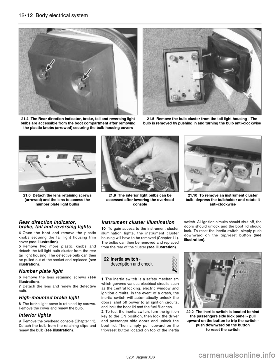
4Open the boot and remove the plastic
knobs securing the tail light housing trim
cover (see illustration).
5Remove two more plastic knobs and
detach the tail light bulb cluster from the rear
tail light housing. The defective bulb can then
be pulled out of the socket and replaced (see
illustration).
Number plate light
6Remove the lens retaining screws (see
illustration).
7Detach the lens and renew the defective
bulb.
High-mounted brake light
8The brake light cover is retained by screws.
Remove the cover and renew the bulb.
Interior lights
9Remove the overhead console (Chapter 11).
Detach the bulb from the retaining clips and
renew the bulb (see illustration).
Instrument cluster illumination
10To gain access to the instrument cluster
illumination lights, the instrument cluster
housing will have to be removed (Chapter 11).
The bulbs can then be removed and replaced
from the rear of the cluster (see illustration).
22 Inertia switch-
description and check
1
1The inertia switch is a safety mechanism
which governs various electrical circuits such
as the central locking, electric window and
ignition circuits. In the event of a crash, the
inertia switch will automatically unlock the
doors, shut off power to all ignition circuits,
and lock the boot lid and the fuel filler cap.
2To test the inertia switch, turn the ignition
key to the ON position, then lock the driver
and passenger side doors and unlock the
boot lid. Then simply pull upward on the
trip/reset button located on top of the inertiaswitch. All ignition circuits should shut off, the
doors should unlock and the boot lid should
lock. To reset the inertia switch, simply push
downward on the trip/reset button (see
illustration).
12•12 Body electrical system
21.6 Detach the lens retaining screws
(arrowed) and the lens to access the
number plate light bulbs21.9 The interior light bulbs can be
accessed after lowering the overhead
console21.10 To remove an instrument cluster
bulb, depress the bulbholder and rotate it
anti-clockwise
3261 Jaguar XJ6 21.4 The Rear direction indicator, brake, tail and reversing light
bulbs are accessible from the boot compartment after removing
the plastic knobs (arrowed) securing the bulb housing covers
21.5 Remove the bulb cluster from the tail light housing - The
bulb is removed by pushing in and turning the bulb anti-clockwise
22.2 The inertia switch is located behind
the passengers side kick panel - pull
upward on the button to trip the switch -
push downward on the button
to reset the switch
Page 175 of 227
23 Cruise control system-
description and check
5
1The cruise control system maintains vehicle
speed with an independently operated vacuum
motor located on the passenger’s side inner
wing in the engine compartment. When the
cruise control switch is turned on, a vacuum
actuator (connected the throttle linkage) is
activated by vacuum from the vacuum motor.
The system consists of the vacuum motor,
vacuum actuator, brake switch, control
switches, a relay and associated vacuum
hoses. Some features of the system require
special testers and diagnostic procedures
which are beyond the scope of this manual.
Listed below are some general procedures that
may be used to locate common problems.
2Locate and check the fuse (see Section 3).
3Have an assistant operate the brake lights
while you check their operation (voltage from
the brake light switch deactivates the cruise
control).
4If the brake lights don’t come on or don’t
shut off, correct the problem and re-test the
cruise control.
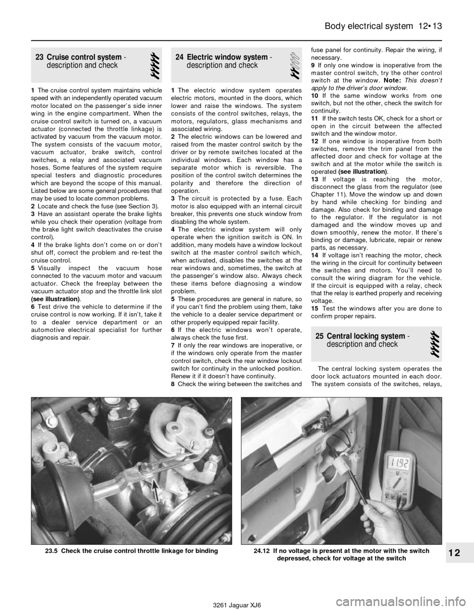
5Visually inspect the vacuum hose
connected to the vacuum motor and vacuum
actuator. Check the freeplay between the
vacuum actuator stop and the throttle link slot
(see illustration).
6Test drive the vehicle to determine if the
cruise control is now working. If it isn’t, take it
to a dealer service department or an
automotive electrical specialist for further
diagnosis and repair.
24 Electric window system-
description and check
2
1The electric window system operates
electric motors, mounted in the doors, which
lower and raise the windows. The system
consists of the control switches, relays, the
motors, regulators, glass mechanisms and
associated wiring.
2The electric windows can be lowered and
raised from the master control switch by the
driver or by remote switches located at the
individual windows. Each window has a
separate motor which is reversible. The
position of the control switch determines the
polarity and therefore the direction of
operation.
3The circuit is protected by a fuse. Each
motor is also equipped with an internal circuit
breaker, this prevents one stuck window from
disabling the whole system.
4The electric window system will only
operate when the ignition switch is ON. In
addition, many models have a window lockout
switch at the master control switch which,
when activated, disables the switches at the
rear windows and, sometimes, the switch at
the passenger’s window also. Always check
these items before diagnosing a window
problem.
5These procedures are general in nature, so
if you can’t find the problem using them, take
the vehicle to a dealer service department or
other properly equipped repair facility.
6If the electric windows won’t operate,
always check the fuse first.
7If only the rear windows are inoperative, or
if the windows only operate from the master
control switch, check the rear window lockout
switch for continuity in the unlocked position.
Renew it if it doesn’t have continuity.
8Check the wiring between the switches andfuse panel for continuity. Repair the wiring, if
necessary.
9If only one window is inoperative from the
master control switch, try the other control
switch at the window. Note:This doesn’t
apply to the driver’s door window.
10If the same window works from one
switch, but not the other, check the switch for
continuity.
11If the switch tests OK, check for a short or
open in the circuit between the affected
switch and the window motor.
12If one window is inoperative from both
switches, remove the trim panel from the
affected door and check for voltage at the
switch and at the motor while the switch is
operated (see illustration).
13If voltage is reaching the motor,
disconnect the glass from the regulator (see
Chapter 11). Move the window up and down
by hand while checking for binding and
damage. Also check for binding and damage
to the regulator. If the regulator is not
damaged and the window moves up and
down smoothly, renew the motor. If there’s
binding or damage, lubricate, repair or renew
parts, as necessary.
14If voltage isn’t reaching the motor, check
the wiring in the circuit for continuity between
the switches and motors. You’ll need to
consult the wiring diagram for the vehicle.
If the circuit is equipped with a relay, check
that the relay is earthed properly and receiving
voltage.
15Test the windows after you are done to
confirm proper repairs.
25 Central locking system-
description and check
5
The central locking system operates the
door lock actuators mounted in each door.
The system consists of the switches, relays,
Body electrical system 12•13
12
3261 Jaguar XJ6 23.5 Check the cruise control throttle linkage for binding
24.12 If no voltage is present at the motor with the switch
depressed, check for voltage at the switch
Page 176 of 227
actuators, a control unit and associated
wiring. Diagnosis can usually be limited to
simple checks of the wiring connections and
actuators for minor faults which can be easily
repaired. Since this system uses an electronic
control unit, in-depth diagnosis should be left
to a dealership service department.
Central locking systems are operated by bi-
directional solenoids located in the doors. The
lock switches have two operating positions;
Lock and Unlock. When activated, the switch
sends a signal to the door lock control unit to
lock or unlock the doors. Depending on which
way the switch is activated, the control unit
reverses polarity to the solenoids, allowing the
two sides of the circuit to be used alternately
as the feed (positive) and earth side.
Some vehicles may have an anti-theft
system incorporated into the locks. If you are
unable to locate the trouble using the following
general paragraphs, consult a dealer service
department or other properly equipped repair
facility.
1Always check the circuit protection first.
Some vehicles use a combination of circuit
breakers and fuses.
2Operate the door lock switches in both
directions (Lock and Unlock) with the engine off.
Listen for the click of the solenoids operating.
3Test the switches for continuity. Renew the
switch if there’s not continuity in both switch
positions.
4Check the wiring between the switches,
control unit and solenoids for continuity.
Repair the wiring if there’s no continuity.
5Check for a bad earth at the switches or the
control unit.
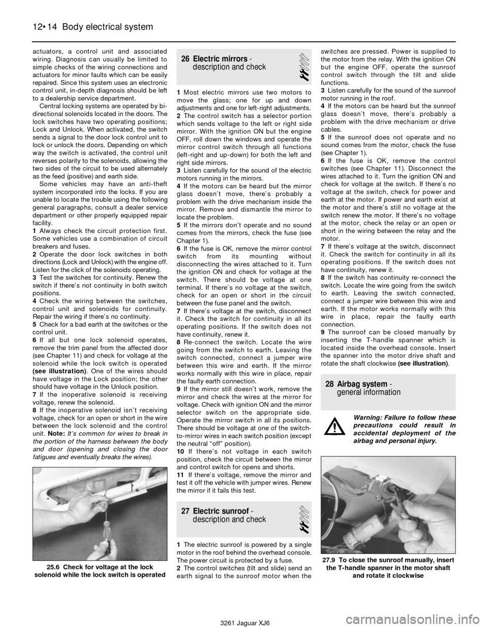
6If all but one lock solenoid operates,
remove the trim panel from the affected door
(see Chapter 11) and check for voltage at the
solenoid while the lock switch is operated
(see illustration). One of the wires should
have voltage in the Lock position; the other
should have voltage in the Unlock position.
7If the inoperative solenoid is receiving
voltage, renew the solenoid.
8If the inoperative solenoid isn’t receiving
voltage, check for an open or short in the wire
between the lock solenoid and the control
unit. Note:It’s common for wires to break in
the portion of the harness between the body
and door (opening and closing the door
fatigues and eventually breaks the wires).26 Electric mirrors-
description and check
2
1Most electric mirrors use two motors to
move the glass; one for up and down
adjustments and one for left-right adjustments.
2The control switch has a selector portion
which sends voltage to the left or right side
mirror. With the ignition ON but the engine
OFF, roll down the windows and operate the
mirror control switch through all functions
(left-right and up-down) for both the left and
right side mirrors.
3Listen carefully for the sound of the electric
motors running in the mirrors.
4If the motors can be heard but the mirror
glass doesn’t move, there’s probably a
problem with the drive mechanism inside the
mirror. Remove and dismantle the mirror to
locate the problem.
5If the mirrors don’t operate and no sound
comes from the mirrors, check the fuse (see
Chapter 1).
6If the fuse is OK, remove the mirror control
switch from its mounting without
disconnecting the wires attached to it. Turn
the ignition ON and check for voltage at the
switch. There should be voltage at one
terminal. If there’s no voltage at the switch,
check for an open or short in the circuit
between the fuse panel and the switch.
7If there’s voltage at the switch, disconnect
it. Check the switch for continuity in all its
operating positions. If the switch does not
have continuity, renew it.
8Re-connect the switch. Locate the wire
going from the switch to earth. Leaving the
switch connected, connect a jumper wire
between this wire and earth. If the mirror
works normally with this wire in place, repair
the faulty earth connection.
9If the mirror still doesn’t work, remove the
mirror and check the wires at the mirror for
voltage. Check with ignition ON and the mirror
selector switch on the appropriate side.
Operate the mirror switch in all its positions.
There should be voltage at one of the switch-
to-mirror wires in each switch position (except
the neutral “off” position).
10If there’s not voltage in each switch
position, check the circuit between the mirror
and control switch for opens and shorts.
11If there’s voltage, remove the mirror and
test it off the vehicle with jumper wires. Renew
the mirror if it fails this test.
27 Electric sunroof-
description and check
2
1The electric sunroof is powered by a single
motor in the roof behind the overhead console.
The power circuit is protected by a fuse.
2The control switches (tilt and slide) send an
earth signal to the sunroof motor when theswitches are pressed. Power is supplied to
the motor from the relay. With the ignition ON
but the engine OFF, operate the sunroof
control switch through the tilt and slide
functions.
3Listen carefully for the sound of the sunroof
motor running in the roof.
4If the motors can be heard but the sunroof
glass doesn’t move, there’s probably a
problem with the drive mechanism or drive
cables.
5If the sunroof does not operate and no
sound comes from the motor, check the fuse
(see Chapter 1).
6If the fuse is OK, remove the control
switches (see Chapter 11). Disconnect the
wires attached to it. Turn the ignition ON and
check for voltage at the switch. If there’s no
voltage at the switch, check for power and
earth at the motor. If power and earth exist at
the motor and there’s still no voltage at the
switch renew the motor. If there’s no voltage
at the motor, check the relay or an open or
short in the wiring between the relay and the
motor.
7If there’s voltage at the switch, disconnect
it. Check the switch for continuity in all its
operating positions. If the switch does not
have continuity, renew it.
8If the switch has continuity re-connect the
switch. Locate the wire going from the switch
to earth. Leaving the switch connected,
connect a jumper wire between this wire and
earth. If the motor works normally with this
wire in place, repair the faulty earth
connection.
9The sunroof can be closed manually by
inserting the T-handle spanner which is
located inside the overhead console. Insert
the spanner into the motor drive shaft and
rotate the shaft clockwise (see illustration).
28 Airbag system-
general information
Warning: Failure to follow these
precautions could result in
accidental deployment of the
airbag and personal injury.
12•14 Body electrical system
25.6 Check for voltage at the lock
solenoid while the lock switch is operated27.9 To close the sunroof manually, insert
the T-handle spanner in the motor shaft
and rotate it clockwise
3261 Jaguar XJ6
Page 177 of 227
Later models are equipped with a
Supplemental Restraint System (SRS), more
commonly known as an airbag. This system is
designed to protect the driver, and on 1994
models, the passenger from serious injury in
the event of a head-on or frontal collision. It
consists of an airbag module in the centre of
the steering wheel and a passenger airbag
module on the right side of the dash above
the glove box on 1994 models.
The airbag modules contain an inflater and
a sensor assembly which activates from
impact energy that is transmitted through the
body and steering column upon impact or
collision.
DO NOT try to dismantle or remove any
component in the vicinity of the steering
column or instrument panel on models
equipped with air bags. Serious personalinjury or damage may result. The
manufacturer recommends that, on airbag
equipped models, service which requires
removal of any component in the vicinity of
the instrument panel or steering column
should be left to a dealer service department
or other properly equipped repair facility
because of the special tools and techniques
required to disable the air bag system.
29 Wiring diagrams-
general information
Since it isn’t possible to include a complete
wiring diagram for every year covered by this
manual, the following diagrams are those that
are typical and most commonly needed.Prior to diagnosing any circuits, check the
fuse and circuit breakers (if equipped) to make
sure they are in good condition. Make sure
the battery is properly charged and has clean,
tight cable connections (see Chapter 1).
When checking the wiring system, make
sure that all electrical connectors are clean,
with no broken or loose pins. When
unplugging an electrical connector, do not
pull on the wires, only on the connector
housings themselves.
Body electrical system 12•15
12
3261 Jaguar XJ6 Wiring diagrams commence overleaf
Page 213 of 227
3261 Jaguar XJ6
REF•12Fault finding
Introduction
This Section provides an easy reference guide to the more common
problems which may occur during the operation of your vehicle. These
problems and their possible causes are grouped under headings
denoting various components or systems, such as Engine, Cooling
system, etc. They also refer you to the Chapter and/or Section which
deals with the problem.
Remember that successful troubleshooting is not a mysterious
“black art” practised only by professional mechanics. It is simply the
result of the right knowledge combined with an intelligent, systematic
approach to the problem. Always work by a process of elimination,
starting with the simplest solution and working through to the mostcomplex - and never overlook the obvious. Anyone can run the petrol
tank dry or leave the lights on overnight, so don’t assume that you are
exempt from such oversights.
Finally, always establish a clear idea of why a problem has occurred
and take steps to ensure that it doesn’t happen again. If the electrical
system fails because of a poor connection, check all other connections
in the system to make sure that they don’t fail as well. If a particular
fuse continues to blow, find out why - don’t just replace one fuse after
another. Remember, failure of a small component can often be
indicative of potential failure or incorrect functioning of a more
important component or system.
Engine . . . . . . . . . . . . . . . . . . . . . . . . . . . . . .1
m mEngine backfires
m mEngine diesels (continues to run) after switching off
m mEngine hard to start when cold
m mEngine hard to start when hot
m mEngine lacks power
m mEngine lopes while idling or idles erratically
m mEngine misses at idle speed
m mEngine misses throughout driving speed range
m mEngine rattles at start-up
m mEngine rotates but will not start
m mEngine runs with oil pressure light on
m mEngine stalls
m mEngine starts but stops immediately
m mEngine stumbles on acceleration
m mEngine surges while holding accelerator steady
m mEngine will not rotate when attempting to start1
m mOil puddle under engine
m mPinking or knocking engine sounds during acceleration or uphill
m mStarter motor noisy or excessively rough in engagement
Fuel system . . . . . . . . . . . . . . . . . . . . . . . . .2
m
mExcessive fuel consumption
m mFuel leakage and/or fuel odour
Cooling system . . . . . . . . . . . . . . . . . . . . . .3
m
mCoolant loss
m mExternal coolant leakage
m mInternal coolant leakage
m mOvercooling
m mOverheating
m mPoor coolant circulation
Automatic transmission . . . . . . . . . . . . . . .4
m
mEngine will start in gears other than Park or Neutral
m mFluid leakage
m mShift cable problems
m mTransmission fluid brown or has a burned smell
m mTransmission slips, shifts roughly, is noisy or has no drive
m min forward or reverse gears
m mTransmission will not downshift with accelerator pedal
pressed to the floor
Brakes . . . . . . . . . . . . . . . . . . . . . . . . . . . . . .5
m mBrake pedal feels spongy when depressed
m mBrake pedal travels to the floor with little resistance
m mBrake roughness or chatter (pedal pulsates)
m mDragging brakes
m mExcessive brake pedal travel
m mExcessive pedal effort required to stop vehicle
m mGrabbing or uneven braking action
m mNoise (high-pitched squeal when the brakes are applied)
m mHandbrake does not hold
m mVehicle pulls to one side during braking
Suspension and steering systems . . . . . . .6
m
mAbnormal noise at the front end
m mAbnormal or excessive tyre wear
m mCupped tyres
m mErratic steering when braking
m mExcessive pitching and/or rolling around corners or
during braking
m mExcessive play or looseness in steering system
m mExcessive tyre wear on inside edge
m mExcessive tyre wear on outside edge
m mHard steering
m mPoor returnability of steering to centre
m mRattling or clicking noise in rack-and-pinion
m mShimmy, shake or vibration
m mSuspension bottoms
m mTyre tread worn in one place
m mVehicle pulls to one side
m mWander or poor steering stability
m mWheel makes a “thumping” noise
Electrical system . . . . . . . . . . . . . . . . . . . . .7
Battery will not hold a charge
Discharge warning light fails to come on when key is turned on
Discharge warning light fails to go out
Page 214 of 227
3261 Jaguar XJ6
Fault findingREF•13
1 Engine
Engine will not rotate when attempting to start
m mBattery terminal connections loose or corroded (Chapter 1).
m mBattery discharged or faulty (Chapter 1).
m mDamaged left rear window harness shorting against glass rail
inside door, causing battery to drain (Chapter 12).
m mAutomatic transmission not completely engaged in Park
(Chapter 7).
m mBroken, loose or disconnected wiring in the starting circuit
(Chapters 5 and 12).
m mStarter motor pinion jammed in flywheel ring gear (Chapter 5).
m mStarter solenoid faulty (Chapter 5).
m mStarter motor faulty (Chapter 5).
m mIgnition switch faulty (Chapter 12).
m mStarter pinion or flywheel teeth worn or broken (Chapter 5).
m mInternal engine problem (Chapter 2B).
m mInertia switch activated (Chapter 12).
m mStarter relay defective (Chapter 5).
Engine rotates but will not start
m
mFuel tank empty.
m mBattery discharged (engine rotates slowly) (Chapter 5).
m mBattery terminal connections loose or corroded (Chapter 1).
m mLeaking fuel injector(s), faulty fuel pump, pressure regulator, etc.
(Chapter 4).
m mFuel not reaching fuel injection system (Chapter 4).
m mIgnition components damp or damaged (Chapter 5).
m mFuel injector stuck open (Chapter 4).
m mWorn, faulty or incorrectly gapped spark plugs (Chapter 1).
m mBroken, loose or disconnected wiring in the starting circuit
(Chapter 5).
m mLoose distributor is changing ignition timing (Chapter 1).
m mBroken, loose or disconnected wires at the ignition coil or faulty
coil (Chapter 5).
m m1988 and 1989 models may have electrical connector damage
between the fuel pump relay and the fuel pump (Chapter 12).
m mCoolant temperature sensor shorting on bonnet liner (Chapter 11).
m mDefective Mass Airflow (MAF) sensor (Chapter 6).
Engine hard to start when cold
m
mBattery discharged or low (Chapter 1).
m mFuel system malfunctioning (Chapter 4).
m mInjector(s) leaking (Chapter 4).
m mDistributor rotor carbon tracked (Chapter 5).
m mWater enters the air cleaner housing near the left front wheel arch
(Chapter 4).
Engine hard to start when hot
m mAir filter clogged (Chapter 1).
m mFuel not reaching the fuel injection system (Chapter 4).
m mCorroded battery connections, especially ground (Chapter 1).
m mFuel vaporises at fuel pump inlet. Refit dual fuel pumps
(Chapter 4).
m mFuel vapours from charcoal canister enter intake during idle and
cause idling, stalling and starting problems (Chapter 6).
Starter motor noisy or excessively rough in
engagement
m mPinion or flywheel gear teeth worn or broken (Chapter 5).
m mStarter motor mounting bolts loose or missing (Chapter 5).
Engine starts but stops immediately
m
mLoose or faulty electrical connections at distributor, coil or
alternator (Chapter 5).
m mInsufficient fuel reaching the fuel injector(s) (Chapters 1 and 4).
m mDamaged fuel injection system speed sensors (Chapter 5).
m mFaulty fuel injection relays (Chapter 5).
m mLeaking threaded adapter on the EGR valve - where fitted
(Chapter 6)
Oil puddle under engine
m mSump gasket and/or sump drain bolt seal leaking (Chapter 2).
m mOil pressure sending unit leaking (Chapter 2).
m mValve cover gaskets leaking (Chapter 2).
m mEngine oil seals leaking (Chapter 2).
m mCylinder head rear plate gasket leaking (Chapter 2).
m mAlternator mounting bolt threads leaking oil (Chapter 5).
m mOil cooler or oil cooler lines leaking (Chapter 3).
Engine misses while idling or idles erratically
m
mVacuum leakage (Chapter 2).
m mAir filter clogged (Chapter 1).
m mFuel pump not delivering sufficient fuel to the fuel injection system
(Chapter 4).
m mLeaking head gasket (Chapter 2).
m mTiming belt/chain and/or sprockets worn (Chapter 2).
m mCamshaft lobes worn (Chapter 2).
m mEGR valve stuck open - where fitted (Chapter 6).
Engine misses at idle speed
m
mSpark plugs worn or not gapped properly (Chapter 1).
m mFaulty spark plug leads (Chapter 1).
m mVacuum leaks (Chapter 1).
m mIncorrect ignition timing (Chapter 5).
m mUneven or low compression (Chapter 2).
m mRestricted EGR vacuum hose - where fitted (Chapter 6).
Engine misses throughout driving speed range
m
mFuel filter clogged and/or impurities in the fuel system (Chapter 1).
m mLow fuel output at the injectors (Chapter 4).
m mFaulty or incorrectly gapped spark plugs (Chapter 1).
m mIncorrect ignition timing (Chapter 5).
m mCracked distributor cap, disconnected distributor wires or
damaged distributor components (Chapter 1).
m mLeaking spark plug leads (Chapter 1).
m mFaulty emission system components (Chapter 6).
m mLow or uneven cylinder compression pressures (Chapter 2).
m mWeak or faulty ignition system (Chapter 5).
m mVacuum leak in fuel injection system, intake manifold or vacuum
hoses (Chapter 4).
m mCrankshaft sensor teeth damaged or missing (see Chapter 12).
m mDistributor installed incorrectly (see Chapter 5)
Engine stumbles on acceleration
m
mSpark plugs fouled (Chapter 1).
m mFuel injection system malfunctioning (Chapter 4).
m mFuel filter clogged (Chapters 1 and 4).
m mIncorrect ignition timing (Chapter 5).
m mIntake manifold air leak (Chapter 4).
m mCollapsed or damaged fuel tank caused by blocked EVAP system
- where fitted (see Chapter 6).
Page 215 of 227
3261 Jaguar XJ6
REF•14Fault finding
2 Fuel system
Engine surges while holding accelerator steady
m mIntake air leak (Chapter 4).
m mFuel pump faulty (Chapter 4).
m mLoose fuel injector harness connections (Chapters 4 and 6).
m mDefective ECU (Chapter 6).
Pinking or knocking engine sounds during
acceleration or uphill
m mIncorrect grade of fuel.
m mDistributor installed incorrectly (Chapter 5).
m mFuel injection system in need of adjustment (Chapter 4).
m mImproper or damaged spark plugs or wires (Chapter 1).
m mWorn or damaged distributor components (Chapter 5).
m mFaulty emission system (Chapter 6).
m mVacuum leak (Chapter 4).
m mFuel rail feed (inlet) hose has hardened, resulting in knocking noise
near dash (see Chapter 4).
Engine lacks power
m mIncorrect ignition timing (Chapter 5).
m mExcessive play in distributor shaft (Chapter 5).
m mWorn rotor, distributor cap or wires (Chapters 1 and 5).
m mFaulty or incorrectly gapped spark plugs (Chapter 1).
m mFuel injection system malfunctioning (Chapter 4).
m mFaulty coil (Chapter 5).
m mBrakes binding (Chapter 1).
m mAutomatic transmission fluid level incorrect (Chapter 1).
m mFuel filter clogged and/or impurities in the fuel system (Chapter 1).
m mEmission control system not functioning properly (Chapter 6).
m mLow or uneven cylinder compression pressures (Chapter 2).
Engine rattles at start-up
m
mFailure of upper timing chain tensioner (Chapter 2).
Engine backfires
m
mEmissions system not functioning properly (Chapter 6).
m mIgnition timing incorrect (Chapter 1).
m mFaulty secondary ignition system (cracked spark plug insulator,
faulty plug leads, distributor cap and/or rotor) (Chapters 1 and 5).
m mFuel injection system malfunctioning (Chapter 4).
m mVacuum leak at fuel injector(s), intake manifold or vacuum hoses
(Chapter 4).
Engine stalls
m mIdle speed incorrect (Chapter 1).
m mFuel filter clogged and/or water and impurities in the fuel system
(Chapter 1).
m mDistributor components damp or damaged (Chapter 5).
m mFaulty emissions system components (Chapter 6).
m mFaulty or incorrectly gapped spark plugs (Chapter 1).
m mFaulty spark plug leads (Chapter 1).
m mVacuum leak in the fuel injection system, intake manifold or
vacuum hoses (Chapter 4).
Engine runs with oil pressure light on
m mLow oil level (Chapter 1).
m mIdle rpm too low (Chapter 1).
m mShort in wiring circuit (Chapter 12).
m mFaulty oil pressure sending unit (Chapter 2).
m mWorn engine bearings and/or oil pump (Chapter 2).
Engine diesels (continues to run)
after switching off
m mIdle speed too high (Chapter 4).
m mExcessive engine operating temperature (Chapter 3).
m mIncorrect fuel octane grade.
Excessive fuel consumption
m
mDirty or clogged air filter element (Chapter 1).
m mIncorrectly set ignition timing (Chapter 5).
m mEmissions system not functioning properly (Chapter 6).
m mFuel injection internal parts worn or damaged (Chapter 4).
m mLow tyre pressure or incorrect tyre size (Chapter 1).
Fuel leakage and/or fuel odour
m
mLeak in a fuel feed or vent line (Chapter 4).
m mTank overfilled.
m mFuel injector internal parts excessively worn (Chapter 4).
3 Cooling system
Overheating
m
mInsufficient coolant in system (Chapter 1).
m mWater pump drivebelt defective or out of adjustment (Chapter 1).
m mRadiator core blocked or grille restricted (Chapter 3).
m mThermostat faulty (Chapter 3).
m mRadiator cap not maintaining proper pressure (Chapter 3).
m mIgnition timing incorrect (Chapter 5).
Overcooling
m
mFaulty thermostat (Chapter 3).
External coolant leakage
m
mDeteriorated/damaged hoses; loose clamps (Chapters 1 and 3).
m mWater pump seal defective (Chapters 1 and 3).
m mLeakage from radiator core or manifold tank (Chapter 3).
m mEngine drain or water jacket core plugs leaking (Chapter 2).
m mHoses behind water pump leaking (Chapter 3).
Internal coolant leakage
m
mLeaking cylinder head gasket (Chapter 2).
m mCracked cylinder bore or cylinder head (Chapter 2).
Coolant loss
m
mToo much coolant in system (Chapter 1).
m mCoolant boiling away because of overheating (Chapter 3).
m mInternal or external leakage (Chapter 3).
m mFaulty radiator cap (Chapter 3).
Poor coolant circulation
m
mInoperative water pump (Chapter 3).
m mRestriction in cooling system (Chapters 1 and 3).
m mWater pump drivebelt defective/out of adjustment (Chapter 1).
m mThermostat sticking (Chapter 3).
1 Engine (continued)
Page 216 of 227
3261 Jaguar XJ6
Fault findingREF•15
4 Automatic transmission
Note:Due to the complexity of the automatic transmission, it is difficult
for the home mechanic to properly diagnose and service this
component. For problems other than the following, the vehicle should
be taken to a dealer or transmission workshop.
Fluid leakage
m mAutomatic transmission fluid is a deep red colour. Fluid leaks
should not be confused with engine oil, which can easily be blown
by air flow to the transmission.
m mTo pinpoint a leak, first remove all built-up dirt and grime from the
transmission housing with degreasing agents and/or steam
cleaning. Then drive the vehicle at low speeds so air flow will not
blow the leak far from its source. Raise the vehicle and determine
where the leak is coming from. Common areas of leakage are:
a) Sump pan (Chapters 1 and 7)
b) Dipstick/filler tube (see below)
c) Transmission fluid cooler lines (Chapter 7)
d) Speedometer sensor (Chapter 7)
m mMake sure the dipstick is a tight fit inside the filler tube. If the seal
at the top of the dipstick is worn or damaged, replace the seal or
the dipstick. If fluid continues to leak from the top of the dipstick
tube, inspect the breather, which is a plastic cap secured by a clip
to the top of the extension housing. This breather can be plugged
by the noise-deadening foam installed in the transmission tunnel,
causing transmission fluid to leak from the top of the dipstick
tube.
Transmission fluid brown or has a burned smell
m mTransmission fluid burned (Chapter 1).
Shift cable problems
m
mChapter 7 deals with adjusting the shift cable. Common problems
which may be attributed to a poorly adjusted shift cable are:
a) Engine starting in gears other than Park or Neutral.
b) Indicator on shift lever pointing to a gear other than the one
actually being used.
c) Vehicle moves when in Park.
m mRefer to Chapter 7 for the shift cable adjustment procedure.
Transmission will not downshift
with accelerator pedal pressed to the floor
m mKickdown cable out of adjustment (Chapter 7).
Engine will start in gears
other than Park or Neutral
m mNeutral start/reversing light switch malfunctioning (Chapter 7).
m mShift cable out of adjustment (Chapter 7).
Transmission slips, shifts roughly, is noisy,
or has no drive in forward or reverse gears
m mThere are many probable causes for the above problems, but the
home mechanic should be concerned with only one possibility -
fluid level. Before taking the vehicle to a dealer service department
or transmission repair workshop, check the level and condition of
the fluid as described in Chapter 1. Correct the fluid level as
necessary or change the fluid if needed. If the problem persists,
have a professional diagnose the probable cause.
5 Brakes
Note:Before assuming that a brake problem exists, make sure that:
a) The tyres are in good condition and properly inflated (Chapter 1).
b) The front end alignment is correct (Chapter 10).
c) The vehicle is not loaded with weight in an unequal manner.
Vehicle pulls to one side during braking
m mIncorrect tyre pressures (Chapter 1).
m mFront end out of line (have the front end aligned).
m mUnmatched tyres on same axle.
m mRestricted brake lines or hoses (Chapter 9).
m mMalfunctioning caliper assembly (Chapter 9).
m mLoose suspension parts (Chapter 10).
m mLoose calipers (Chapter 9).
m mBrake pads contaminated with oil or grease (Chapter 9).
Noise (high-pitched squeal
when the brakes are applied)
m mFront and/or rear disc brake pads worn out. The noise comes from
the wear sensor rubbing against the disc. Replace pads with new
ones immediately (Chapter 9).
Brake roughness or chatter (pedal pulsates)
m mExcessive lateral disc runout (Chapter 9).
m mParallelism not within specifications (Chapter 9).
m mUneven pad wear caused by caliper not sliding due to improper
clearance or dirt (Chapter 9).
m mDefective disc (Chapter 9).
Excessive pedal effort required to stop vehicle
m
mMalfunctioning power brake servo (Chapter 9).
m mPartial system failure (Chapter 9).
m mExcessively worn pads (Chapter 9).
m mPiston in caliper stuck or sluggish (Chapter 9).
m mBrake pads contaminated with oil or grease (Chapter 9).
m mNew pads installed and not yet seated. It will take a while for the
new material to seat against the disc.
m mAccumulator in power hydraulic system defective (see a Jaguar
dealer).
Excessive brake pedal travel
m mPartial brake system failure (Chapter 9).
m mInsufficient fluid in master cylinder (Chapters 1 and 9).
m mAir trapped in system (Chapters 1 and 9).
Dragging brakes
m
mMaster cylinder pistons not returning correctly (Chapter 9).
m mRestricted brakes lines or hoses (Chapters 1 and 9).
m mIncorrect handbrake adjustment (Chapter 9).
Grabbing or uneven braking action
m
mMalfunction of power brake servo unit (Chapter 9).
m mBinding brake pedal mechanism (Chapter 9).
m mBrake pads contaminated with oil or grease (Chapter 9).
Page 217 of 227
3261 Jaguar XJ6
REF•16Fault finding
6 Suspension and steering systems
5 Braking system (continued)
Brake pedal feels spongy when depressed
m mAir in hydraulic lines (Chapter 9).
m mMaster cylinder mounting bolts loose (Chapter 9).
m mMaster cylinder defective (Chapter 9).
Brake pedal travels to the floor - no resistance
m
mLittle or no fluid in the master cylinder reservoir caused by leaking
caliper piston(s), damaged or disconnected brake lines (Chapter 9).
Handbrake does not hold
m mHandbrake cable or handbrake shoes improperly adjusted
(Chapter 9).
m mHandbrake shoes need replacement (Chapter 9).
Note:Before attempting to diagnose the suspension and steering
systems, perform the following preliminary checks:
a) Tyres for wrong pressure and uneven wear.
b) Steering universal joints from the column to the steering gear for
loose connectors or wear.
c) Front and rear suspension and the rack and pinion assembly for
loose or damaged parts.
d) Out-of-round or out-of-balance tyres, bent rims and loose and/or
rough wheel bearings.
Vehicle pulls to one side
m mMismatched or uneven tyres (Chapter 10).
m mBroken or sagging springs (Chapter 10).
m mWheel alignment out of specifications (Chapter 10).
m mFront brakes dragging (Chapter 9).
Abnormal or excessive tyre wear
m
mWheel alignment out of specifications (Chapter 10).
m mSagging or broken springs (Chapter 10).
m mTyre out-of-balance (Chapter 10).
m mWorn shock absorber (Chapter 10).
m mOverloaded vehicle.
m mTyres not rotated regularly.
Wheel makes a “thumping” noise
m
mBlister or bump on tyre (Chapter 10).
m mImproper shock absorber action (Chapter 10).
Shimmy, shake or vibration
m
mTyre or wheel out-of-balance or out-of-round (Chapter 10).
m mLoose, worn or out-of-adjustment wheel bearings (Chapter 1).
m mWorn tie-rod ends (Chapter 10).
m mWorn balljoints (Chapter 10).
m mExcessive wheel runout (Chapter 10).
m mBlister or bump on tyre (Chapter 10).
Hard steering
m
mLack of lubrication at balljoints, tie-rod ends and rack-and-pinion
assembly (Chapter 1).
m mFront wheel alignment (Chapter 10).
m mLow tyre pressure(s) (Chapter 1).
Poor returnability of steering to centre
m
mLack of lubrication at balljoints and tie-rod ends (Chapter 1).
m mBinding in balljoints (Chapter 10).
m mBinding in steering column (Chapter 10).
m mLack of lubricant in rack-and-pinion assembly (Chapter 10).
m mFront wheel alignment (Chapter 10).
Abnormal noise at the front end
m
mLack of lubrication at balljoints and tie-rod ends (Chapter 1).
m mDamaged shock absorber mounting (Chapter 10).m mWorn control arm bushings or tie-rod ends (Chapter 10).
m mLoose stabiliser bar (Chapter 10).
m mLoose wheel nuts (Chapter).
m mLoose suspension bolts (Chapter 10).
Wander or poor steering stability
m
mMismatched or uneven tyres (Chapter 10).
m mLack of lubrication at balljoints and tie-rod ends (Chapter 1).
m mWorn shock absorbers (Chapter 10).
m mLoose stabiliser bar (Chapter 10).
m mBroken or sagging springs (Chapter 10).
m mFront or rear wheel alignment (Chapter 10).
Erratic steering when braking
m
mWheel bearings worn (Chapter 1).
m mBroken or sagging springs (Chapter 10).
m mLeaking wheel cylinder or caliper (Chapter 9).
m mWarped discs (Chapter 9).
Excessive pitching and/or rolling around corners
or during braking
m mLoose stabiliser bar (Chapter 10).
m mWorn shock absorbers or mounts (Chapter 10).
m mBroken or sagging springs (Chapter 10).
m mOverloaded vehicle.
Suspension bottoms
m
mOverloaded vehicle.
m mWorn shock absorbers (Chapter 10).
m mIncorrect, broken or sagging springs (Chapter 10).
m mDefective power hydraulic system or leaking rear shock absorbers
(Chapter 10).
Cupped tyres (wear on both edges)
m mFront wheel or rear wheel alignment (Chapter 10).
m mWorn shock absorbers (Chapter 10).
m mWheel bearings worn (Chapter 10).
m mExcessive tyre or wheel runout (Chapter 10).
m mWorn balljoints (Chapter 10).
Excessive tyre wear on outside edge
m
mInflation pressures incorrect (Chapter 1).
m mExcessive speed in turns.
m mFront end alignment incorrect (excessive toe-in). Have
professionally aligned.
m mSuspension arm bent or twisted (Chapter 10).
Excessive tyre wear on inside edge
m
mInflation pressures incorrect (Chapter 1).
m mFront end alignment incorrect (toe-out). Have professionally
aligned.
m mLoose or damaged steering components (Chapter 10).