dashboard JAGUAR XJ6 1997 2.G Workshop Manual
[x] Cancel search | Manufacturer: JAGUAR, Model Year: 1997, Model line: XJ6, Model: JAGUAR XJ6 1997 2.GPages: 227, PDF Size: 7.2 MB
Page 75 of 227
Heating system
The heating system consists of two blower
fans, one under the dash on the right and one
on the left, and a heater core located within
the heater/air conditioning assembly which is
under the dash and behind the console.
Hoses connect the heater core to the engine
cooling system. Heater function is controlled
by the heater/air conditioning control head on
the dashboard. Hot engine coolant is
circulated through the heater core. When the
heater mode is activated, a flap door opens to
expose the heater box to the passenger
compartment. A fan switch on the control
head activates the blower motor, which forces
air through the core, heating the air.
Air conditioning system
The air conditioning system consists of a
condenser mounted in front of the radiator, an
evaporator mounted in the heat/air
conditioning assembly behind the console and
under the centre of the dash, a compressor
mounted on the engine, a filter-drier which
contains a high pressure relief valve and the
plumbing connecting all of the above.
A blower fan forces the warmer air of the
passenger compartment through the
evaporator core (sort of a radiator-in-reverse),
transferring the heat from the air to the
refrigerant. The liquid refrigerant boils off into
low pressure vapour, taking the heat with it
when it leaves the evaporator. The
compressor keeps refrigerant circulating
through the system, pumping the warmed
coolant through the condenser where it is
cooled and then circulated back to the
evaporator.
2 Antifreeze/coolant-
general information
Warning: Do not allow antifreeze
to come in contact with your
skin or painted surfaces of the
vehicle. Rinse off spills immediately withplenty of water. Antifreeze is highly toxic if
ingested. Never leave antifreeze lying
around in an open container or in puddles
on the floor; children and pets are
attracted by it’s sweet smell and may drink
it. Check with local authorities about
disposing of used antifreeze. Many
communities have collection centres which
will see that antifreeze is disposed of
safely. Never dump used antifreeze on the
ground or into drains.
Note:Non-toxic antifreeze is now
manufactured and available at local car
accessory outlets, but even these types
should be disposed of properly.
The cooling system should be filled with a
water/ethylene-glycol based antifreeze
solution, which will prevent freezing down to
at least -20° F, or lower if local climate
requires it. It also provides protection against
corrosion and increases the coolant boiling
point.
The cooling system should be drained,
flushed and refilled every 24,000 miles or
every two years (see Chapter 1). The use of
antifreeze solutions for periods of longer than
two years is likely to cause damage and
encourage the formation of rust and scale in
the system. If your tap water is “hard”, i.e.
contains a lot of dissolved minerals, use
distilled water with the antifreeze.
Before adding antifreeze to the system,
check all hose connections, because
antifreeze tends to leak through very minute
openings. Engines do not normally consume
coolant. Therefore, if the level goes down, find
the cause and correct it.
The exact mixture of antifreeze-to-water
you should use depends on the relative
weather conditions. The mixture should
contain at least 50-percent antifreeze, but
should never contain more than 70-percent
antifreeze. Consult the mixture ratio chart on
the antifreeze container before adding
coolant. Hydrometers are available at most
car accessory outlets to test the ratio
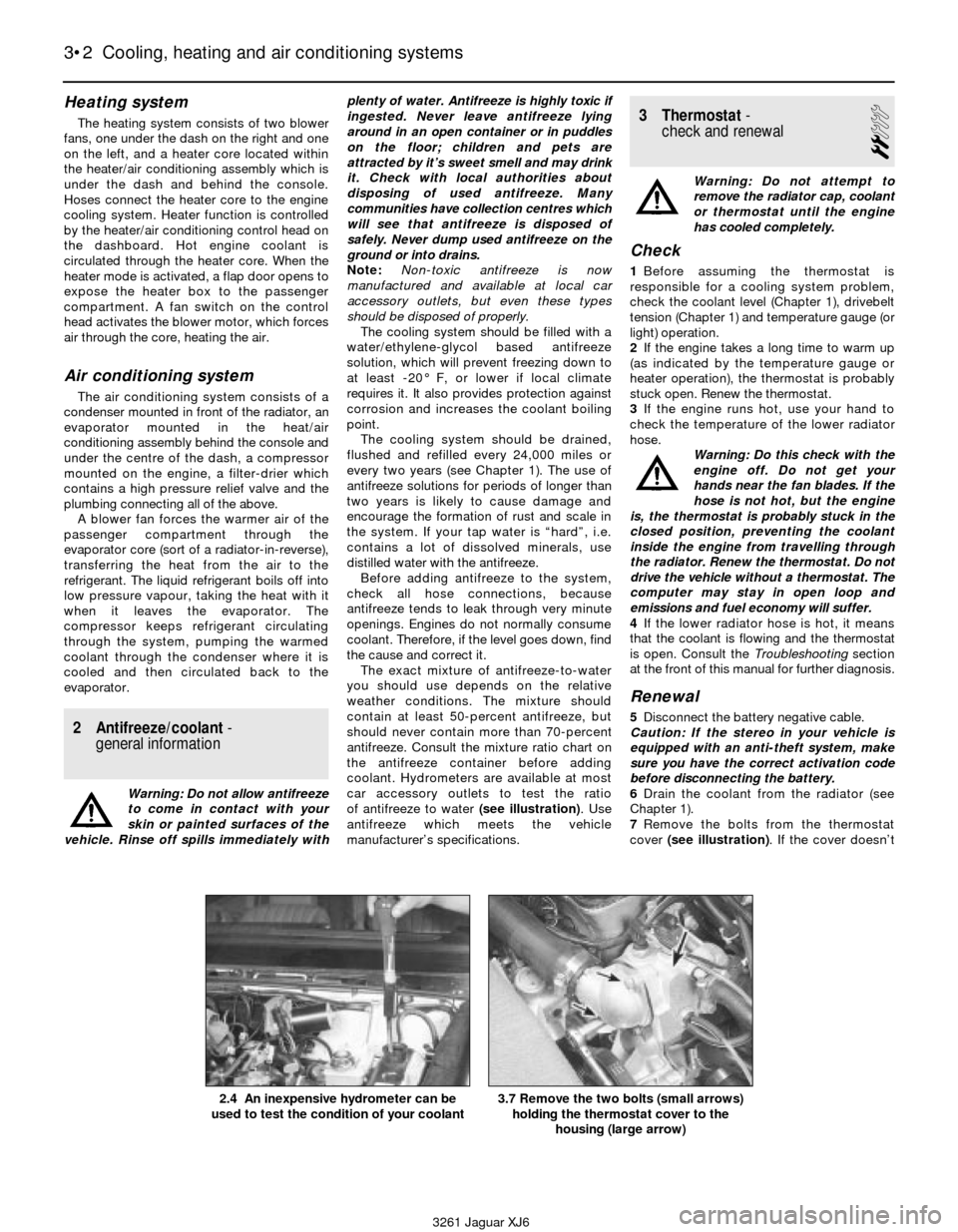
of antifreeze to water (see illustration). Use
antifreeze which meets the vehicle
manufacturer’s specifications.
3 Thermostat-
check and renewal
2
Warning: Do not attempt to
remove the radiator cap, coolant
or thermostat until the engine
has cooled completely.
Check
1Before assuming the thermostat is
responsible for a cooling system problem,
check the coolant level (Chapter 1), drivebelt
tension (Chapter 1) and temperature gauge (or
light) operation.
2If the engine takes a long time to warm up
(as indicated by the temperature gauge or
heater operation), the thermostat is probably
stuck open. Renew the thermostat.
3If the engine runs hot, use your hand to
check the temperature of the lower radiator
hose.
Warning: Do this check with the
engine off. Do not get your
hands near the fan blades. If the
hose is not hot, but the engine
is, the thermostat is probably stuck in the
closed position, preventing the coolant
inside the engine from travelling through
the radiator. Renew the thermostat. Do not
drive the vehicle without a thermostat. The
computer may stay in open loop and
emissions and fuel economy will suffer.
4If the lower radiator hose is hot, it means
that the coolant is flowing and the thermostat
is open. Consult the Troubleshootingsection
at the front of this manual for further diagnosis.
Renewal
5Disconnect the battery negative cable.
Caution: If the stereo in your vehicle is
equipped with an anti-theft system, make
sure you have the correct activation code
before disconnecting the battery.
6Drain the coolant from the radiator (see
Chapter 1).
7Remove the bolts from the thermostat
cover (see illustration). If the cover doesn’t
3•2 Cooling, heating and air conditioning systems
3261 Jaguar XJ6 2.4 An inexpensive hydrometer can be
used to test the condition of your coolant
3.7 Remove the two bolts (small arrows)
holding the thermostat cover to the
housing (large arrow)
Page 107 of 227
Refitting
7Insert the distributor into the engine in
exactly the same relationship to the block that
it was in when removed.
8If the distributor does not seat completely,
recheck the alignment marks between the
distributor base and the block to verify that
the distributor is in the same position it was in
before removal. Also check the rotor to see if
it’s aligned with the mark you made on the
edge of the distributor base.
9Refit the distributor hold-down bolt(s).
10The remainder of refitting is the reverse of
removal.
10 Charging system- general
information and precautions
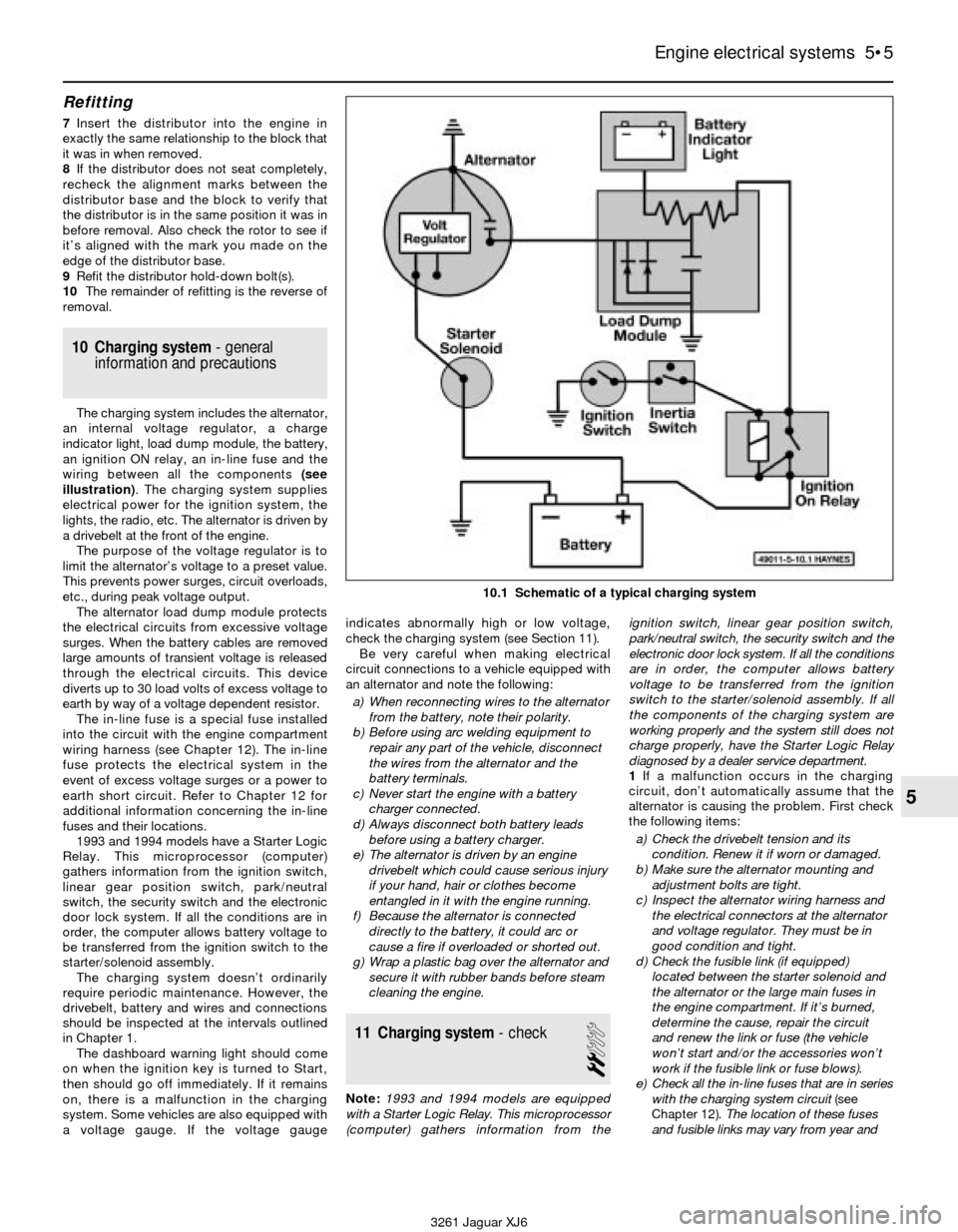
The charging system includes the alternator,
an internal voltage regulator, a charge
indicator light, load dump module, the battery,
an ignition ON relay, an in-line fuse and the
wiring between all the components (see
illustration). The charging system supplies
electrical power for the ignition system, the
lights, the radio, etc. The alternator is driven by
a drivebelt at the front of the engine.
The purpose of the voltage regulator is to
limit the alternator’s voltage to a preset value.
This prevents power surges, circuit overloads,
etc., during peak voltage output.
The alternator load dump module protects
the electrical circuits from excessive voltage
surges. When the battery cables are removed
large amounts of transient voltage is released
through the electrical circuits. This device
diverts up to 30 load volts of excess voltage to
earth by way of a voltage dependent resistor.
The in-line fuse is a special fuse installed
into the circuit with the engine compartment
wiring harness (see Chapter 12). The in-line
fuse protects the electrical system in the
event of excess voltage surges or a power to
earth short circuit. Refer to Chapter 12 for
additional information concerning the in-line
fuses and their locations.
1993 and 1994 models have a Starter Logic
Relay. This microprocessor (computer)
gathers information from the ignition switch,
linear gear position switch, park/neutral
switch, the security switch and the electronic
door lock system. If all the conditions are in
order, the computer allows battery voltage to
be transferred from the ignition switch to the
starter/solenoid assembly.
The charging system doesn’t ordinarily
require periodic maintenance. However, the
drivebelt, battery and wires and connections
should be inspected at the intervals outlined
in Chapter 1.
The dashboard warning light should come
on when the ignition key is turned to Start,
then should go off immediately. If it remains
on, there is a malfunction in the charging
system. Some vehicles are also equipped with
a voltage gauge. If the voltage gaugeindicates abnormally high or low voltage,
check the charging system (see Section 11).
Be very careful when making electrical
circuit connections to a vehicle equipped with
an alternator and note the following:
a) When reconnecting wires to the alternator
from the battery, note their polarity.
b) Before using arc welding equipment to
repair any part of the vehicle, disconnect
the wires from the alternator and the
battery terminals.
c) Never start the engine with a battery
charger connected.
d) Always disconnect both battery leads
before using a battery charger.
e) The alternator is driven by an engine
drivebelt which could cause serious injury
if your hand, hair or clothes become
entangled in it with the engine running.
f) Because the alternator is connected
directly to the battery, it could arc or
cause a fire if overloaded or shorted out.
g) Wrap a plastic bag over the alternator and
secure it with rubber bands before steam
cleaning the engine.
11 Charging system- check
2
Note:1993 and 1994 models are equipped
with a Starter Logic Relay. This microprocessor
(computer) gathers information from theignition switch, linear gear position switch,
park/neutral switch, the security switch and the
electronic door lock system. If all the conditions
are in order, the computer allows battery
voltage to be transferred from the ignition
switch to the starter/solenoid assembly. If all
the components of the charging system are
working properly and the system still does not
charge properly, have the Starter Logic Relay
diagnosed by a dealer service department.
1If a malfunction occurs in the charging
circuit, don’t automatically assume that the
alternator is causing the problem. First check
the following items:
a) Check the drivebelt tension and its
condition. Renew it if worn or damaged.
b) Make sure the alternator mounting and
adjustment bolts are tight.
c) Inspect the alternator wiring harness and
the electrical connectors at the alternator
and voltage regulator. They must be in
good condition and tight.
d) Check the fusible link (if equipped)
located between the starter solenoid and
the alternator or the large main fuses in
the engine compartment. If it’s burned,
determine the cause, repair the circuit
and renew the link or fuse (the vehicle
won’t start and/or the accessories won’t
work if the fusible link or fuse blows).
e) Check all the in-line fuses that are in series
with the charging system circuit (see
Chapter 12).The location of these fuses
and fusible links may vary from year and
Engine electrical systems 5•5
5
10.1 Schematic of a typical charging system
3261 Jaguar XJ6
Page 113 of 227
2The CHECK ENGINE warning light, which is
located on the instrument panel, comes on
when the ignition switch is turned to ON and
the engine is not running. When the engine is
started, the warning light should go out. If the
light remains on, the self-diagnosis system
has detected a malfunction. Note: The
CHECK ENGINE light on early models is
displayed on the dashboard VCM panel on the
right side. Later models are equipped with a
separate CHECK ENGINE light on the left side
of the instrument cluster.Note:Not all the
codes will cause the CHECK ENGINE light to
activate. When performing any fuel or
emissions systems diagnosis, always check
for codes that may be stored but not indicated
by the CHECK ENGINE light.
Obtaining fault code output
3To obtain an output of diagnostic codes,
verify first that the battery voltage is above 11
volts, the throttle is fully closed, the
transmission is in Park, the accessory
switches are off and the engine is at normal
operating temperature.
4Turn the ignition switch to ON but don’t
start the engine (Position II). Note:On 1988
and 1989 models, remember to turn the
ignition switch to position II without turning
the key to OFF.
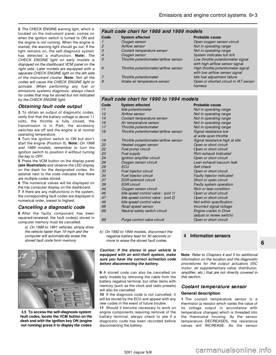
5Press the VCM button on the display panel
(see illustration)and observe the LED display
on the dash for the designated codes. An
asterisk next to the code indicates that there
are multiple codes stored.
6The numerical values will be displayed on
the trip computer display on the dashboard.
7If there are any malfunctions in the system,
the corresponding fault codes are displayed in
numerical order, lowest to highest.
Cancelling a diagnostic code
8After the faulty component has been
repaired/renewed, the fault code(s) stored in
computer memory must be cancelled.
a) On 1988 to 1991 vehicles, simply drive
the vehicle faster than 19 mph and the
computer will automatically erase the
stored fault code from memory.b) On 1992 to 1994 models, disconnect the
negative battery lead for 30 seconds or
more to erase the stored fault codes.
Caution: If the stereo in your vehicle is
equipped with an anti-theft system, make
sure you have the correct activation code
before disconnecting the battery.
9A stored code can also be cancelled on
early models by removing the cable from the
battery negative terminal, but other items with
memory (such as the clock and radio presets)
will also be cancelled.
10If the diagnosis code is not cancelled, it
will be stored by the ECU and appear with any
new codes in the event of future trouble.
11Should it become necessary to work on
engine components requiring removal of the
battery terminal, always check to see if a
diagnostic code has been recorded before
disconnecting the battery.
4 Information sensors
Note: Refer to Chapters 4 and 5 for additional
information on the location and the diagnostic
procedures for the output actuators (ISC
motor, air supplementary valve, distributor,
amplifier, etc.) that are not directly covered in
this section.
Coolant temperature sensor
General description
1The coolant temperature sensor is a
thermistor (a resistor which varies the value of
its voltage output in accordance with
temperature changes) which is threaded into
the thermostat housing. As the sensor
temperature DECREASES, the resistance
values will INCREASE. As the sensor
Emissions and engine control systems 6•3
6
3.5 To access the self-diagnosis system
fault codes, locate the VCM button on the
dash and with the ignition key ON (engine
not running) press it to display the codes
3261 Jaguar XJ6
Fault code chart for 1988 and 1989 models
Code System affected Probable cause
1 Oxygen sensor Open oxygen sensor circuit
2 Airflow sensor Not in operating range
3 Coolant temperature sensor Not in operating range
4 Oxygen sensor System indicates full rich
5 Throttle potentiometer/airflow sensor Low throttle potentiometer signal
with high airflow sensor signal
6 Throttle potentiometer/airflow sensor High throttle potentiometer signal
with low airflow sensor signal
7 Throttle potentiometer Idle fuel adjustment failure
8 Intake air temperature sensor Open or shorted circuit in IAT sensor
harness
Fault code chart for 1990 to 1994 models
Code System affected Probable cause
11 Idle potentiometer Not in operating range
12 Airflow sensor Not in operating range
14 Coolant temperature sensor Not in operating range
16 Air temperature sensor Not in operating range
17 Throttle potentiometer Not in operating range
18 Throttle potentiometer/airflow sensor Signal resistance low
at wide open throttle
19 Throttle potentiometer/airflow sensor Signal resistance high at idle
22 Heated oxygen sensor Open or short circuit
22 Fuel pump circuit Open or short circuit
23 Fuel supply Rich exhaust Indicated
24 Ignition amplifier circuit Open or short circuit
26 Oxygen sensor circuit Lean exhaust/vacuum leak
29 ECU Self check
33 Fuel injector circuit Open or short circuit
34 Fuel injector circuit Faulty injector indicated
37 EGR solenoid circuit Short or open circuit
39 EGR circuit Faulty system operation
44 Oxygen sensor circuit Rich or lean condition
46 Idle speed control valve - (coil 1) Open or short circuit
47 Idle speed control valve - (coil 2) Open or short circuit
48 Idle speed control valve Not within specification
68 Road speed sensor Incorrect signal voltage
69 Neutral safety switch circuit Engine cranks in Drive
(adjust or renew switch)
89 Purge control valve circuit Open or short circuit
Page 124 of 227
Test the brakes at various speeds with both
light and heavy pedal pressure. The vehicle
should stop evenly without pulling to one side
or the other. Avoid locking the brakes,
because this slides the tyres and diminishes
braking efficiency and control of the vehicle.
Tyres, vehicle load and wheel alignment are
factors which also affect braking performance.
2 Anti-lock Brake system
(ABS)- general information
The Anti-lock Brake System is designed to
maintain vehicle steerability, directional stability
and optimum deceleration under severe
braking conditions on most road surfaces. It
does so by monitoring the rotational speed of
each wheel and controlling the brake line
pressure to each wheel during braking. This
prevents the wheels from locking up.
The ABS system has three main units - the
wheel speed sensors, the electronic control unit
and the modulator (hydraulic control unit). The
sensors - one at each wheel - send a variable
voltage signal to the electronic control unit,
which monitors these signals, compares them
to its program and determines whether a wheel
is about to lock up. When a wheel is about to
lock up, the control unit signals the hydraulic
unit to reduce hydraulic pressure (or not
increase it further) at that wheel’s brake caliper.
Pressure modulation is handled by three
electrically-operated solenoid valves - one for
each front wheel and one for the rear wheels -
inside the modulator.
If a problem develops within the system, an
“ABS” warning light will glow on the dashboard.
Sometimes, a visual inspection of the ABS
system can help you locate the problem.
Carefully inspect the ABS wiring harness. Pay
particularly close attention to the harness and
connections near each wheel. Look for signs of
chafing and other damage caused by
incorrectly routed wires. If a wheel sensor
harness is damaged, the sensor should be
replaced (the harness and sensor are integral).
Warning: Do NOT try to repair an
ABS wiring harness. The ABS
system is sensitive to even thesmallest changes in resistance. Repairing
the harness could alter resistance values
and cause the system to malfunction. If the
ABS wiring harness is damaged in any way,
it must be replaced.
Caution: Make sure the ignition is turned
off before unplugging or reattaching any
electrical connections.
Diagnosis and repair
If a dashboard warning light comes on and
stays on while the vehicle is in operation, the
ABS system requires attention. Although
special electronic ABS diagnostic testing tools
are necessary to properly diagnose the system,
you can perform a few preliminary checks
before taking the vehicle to a dealer service
department or other qualified repair workshop.
a) Check the brake fluid level in the master
cylinder reservoir.
b) Verify that all ABS system electrical
connectors in the engine compartment
are plugged in.
c) Check the fuses.
d) Follow the wiring harness to each front
wheel and to the differential sensor and
verify that all connections are secure and
that the wiring is undamaged.
If the above preliminary checks do not
rectify the problem, the vehicle should be
diagnosed by a dealer service department.
Due to the complex nature of this system, all
actual repair work must be done by a dealer
service department or other qualified repair
workshop.
3 Disc brake pads- renewal
2
Warning: Disc brake pads must
be replaced on both front wheels
or both rear wheels at the same
time - never renew the pads on
only one wheel. Also, the dust created by
the brake system may contain asbestos,
which is harmful to your health. Never blow
it out with compressed air and don’t inhale
any of it. An approved filtering mask should
be worn when working on the brakes. Do
not, under any circumstances, use
petroleum-based solvents to clean brake
parts. Use brake system cleaner only!
Note:The following procedure applies to both
the front and rear brake pads.
1Remove the cap from the brake fluid
reservoir and siphon off about two-thirds of
the fluid from the reservoir. Failing to do this
could result in fluid overflowing when the
caliper pistons are pressed into their bores.
2Loosen the wheel nuts, raise the front of the
vehicle and support it securely on axle stands.
3Remove the front wheels. Work on one
brake assembly at a time, using the
assembled brake for reference if necessary.
4Inspect the brake disc (see Section 5).
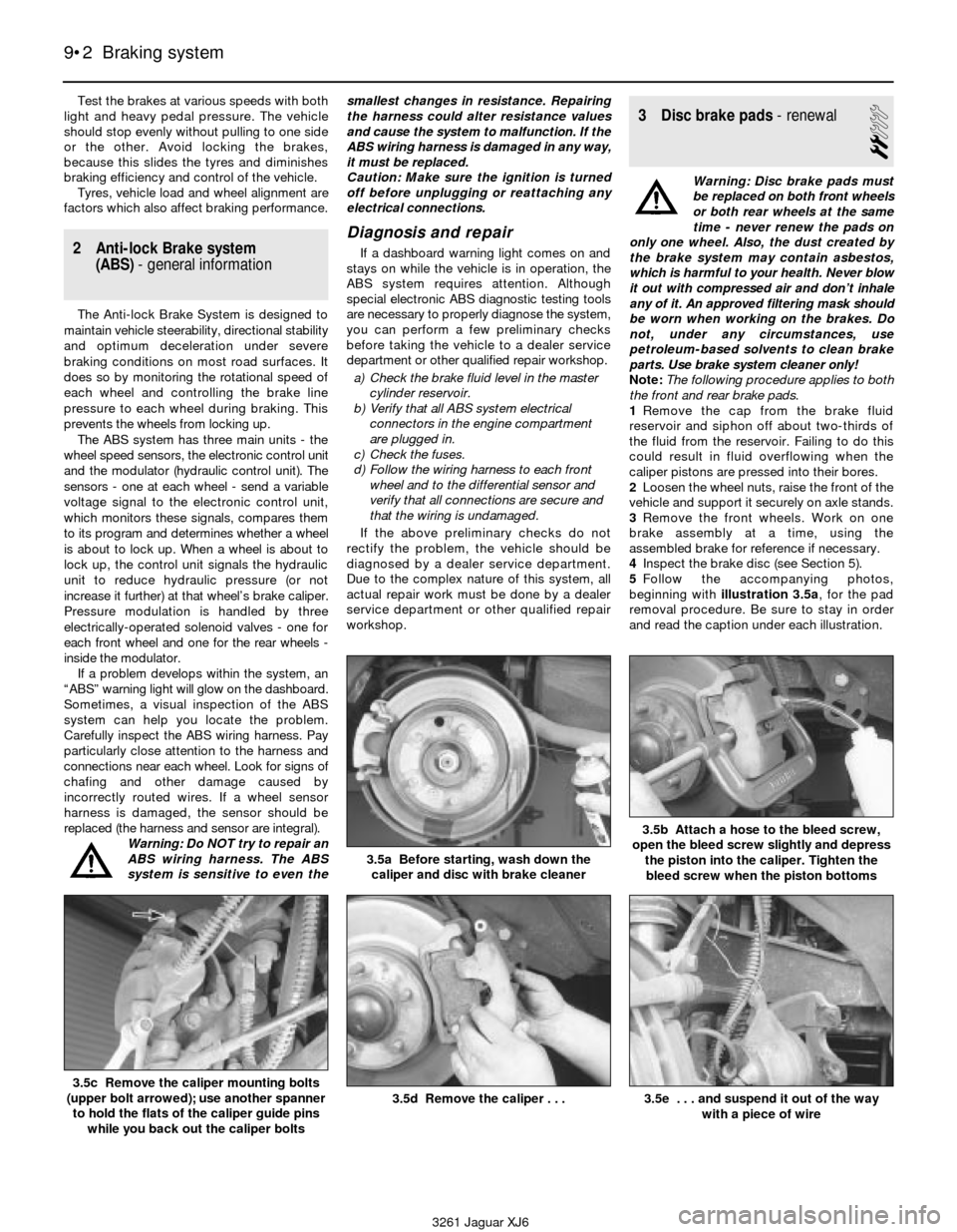
5Follow the accompanying photos,
beginning with illustration 3.5a, for the pad
removal procedure. Be sure to stay in order
and read the caption under each illustration.
9•2 Braking system
3.5a Before starting, wash down the
caliper and disc with brake cleaner
3.5b Attach a hose to the bleed screw,
open the bleed screw slightly and depress
the piston into the caliper. Tighten the
bleed screw when the piston bottoms
3.5c Remove the caliper mounting bolts
(upper bolt arrowed); use another spanner
to hold the flats of the caliper guide pins
while you back out the caliper bolts3.5d Remove the caliper . . .3.5e . . . and suspend it out of the way
with a piece of wire
3261 Jaguar XJ6
Page 149 of 227
3261 Jaguar XJ6
11
Chapter 11
Bodywork and fittings
Body - maintenance . . . . . . . . . . . . . . . . . . . . . . . . . . . . . . . . . . . . . 2
Body repair - major damage . . . . . . . . . . . . . . . . . . . . . . . . . . . . . . . 6
Body repair - minor damage . . . . . . . . . . . . . . . . . . . . . . . . . . . . . . . 5
Bonnet - removal, refitting and adjustment . . . . . . . . . . . . . . . . . . . . 10
Bonnet and boot lid support struts - removal and refitting . . . . . . . . 9
Bonnet release latch and cable - removal and refitting . . . . . . . . . . . 11
Boot lid - removal, refitting and adjustment . . . . . . . . . . . . . . . . . . . 16
Boot lid latch and lock cylinder - removal and refitting . . . . . . . . . . . 17
Bumpers - removal and refitting . . . . . . . . . . . . . . . . . . . . . . . . . . . . 14
Centre console - removal and refitting . . . . . . . . . . . . . . . . . . . . . . . 24
Cowl cover - removal and refitting . . . . . . . . . . . . . . . . . . . . . . . . . . 28
Dashboard trim panels - removal and refitting . . . . . . . . . . . . . . . . . 26
Door - removal, refitting and adjustment . . . . . . . . . . . . . . . . . . . . . . 19
Door latch, lock cylinder and handles - removal and refitting . . . . . . 20
Door trim panel - removal and refitting . . . . . . . . . . . . . . . . . . . . . . . 18Door window glass - removal and refitting . . . . . . . . . . . . . . . . . . . . 22
Door window glass regulator - removal and refitting . . . . . . . . . . . . . 21
Front spoiler - removal and refitting . . . . . . . . . . . . . . . . . . . . . . . . . 13
Front wing - removal and refitting . . . . . . . . . . . . . . . . . . . . . . . . . . . 15
General information . . . . . . . . . . . . . . . . . . . . . . . . . . . . . . . . . . . . . . 1
Hinges and locks - maintenance . . . . . . . . . . . . . . . . . . . . . . . . . . . . 7
Instrument cluster housing - removal and refitting . . . . . . . . . . . . . . 25
Outside mirrors - removal and refitting . . . . . . . . . . . . . . . . . . . . . . . 23
Radiator grille - removal and refitting . . . . . . . . . . . . . . . . . . . . . . . . 12
Seats - removal and refitting . . . . . . . . . . . . . . . . . . . . . . . . . . . . . . . 29
Steering column cover - removal and refitting . . . . . . . . . . . . . . . . . 27
Upholstery and carpets - maintenance . . . . . . . . . . . . . . . . . . . . . . . 4
Vinyl trim - maintenance . . . . . . . . . . . . . . . . . . . . . . . . . . . . . . . . . . 3
Windscreen and fixed glass - replacement . . . . . . . . . . . . . . . . . . . . 8
11•1
Contents
Easy,suitable for
novice with little
experienceFairly easy,suitable
for beginner with
some experienceFairly difficult,
suitable for competent
DIY mechanic
Difficult,suitable for
experienced DIY
mechanicVery difficult,
suitable for expert DIY
or professional
Degrees of difficulty
54321
1 General information
These models feature a “unibody”
construction, using a floor pan with front and
rear frame side rails which support the body
components, front and rear suspension
systems and other mechanical components.
Certain components are particularly vulnerable
to accident damage and can be unbolted and
repaired or replaced. Among these parts are
the body mouldings, bumpers, front wings,
bonnet and boot lids and all glass.
Only general body maintenance practices
and body panel repair procedures within the
scope of the do-it-yourselfer are included in
this Chapter.
2 Body- maintenance
1
1The condition of your vehicle’s body is very
important, because the resale value depends
a great deal on it. It’s much more difficult to
repair a neglected or damaged body than it is
to repair mechanical components. The hidden
areas of the body, such as the wheel wells,
the frame and the engine compartment, areequally important, although they don’t require
as frequent attention as the rest of the body.
2Once a year, or every 12,000 miles, it’s a
good idea to have the underside of the body
steam cleaned. All traces of dirt and oil will be
removed and the area can then be inspected
carefully for rust, damaged brake lines, frayed
electrical wires, damaged cables and other
problems. The front suspension components
should be greased after completion of this job.
3At the same time, clean the engine and the
engine compartment with a steam cleaner or
water soluble degreaser.
4The wheel wells should be given close
attention, since undercoating can peel away
and stones and dirt thrown up by the tyres
can cause the paint to chip and flake, allowing
rust to set in. If rust is found, clean down to
the bare metal and apply an anti-rust paint.
5The body should be washed about once a
week. Wet the vehicle thoroughly to soften the
dirt, then wash it down with a soft sponge and
plenty of clean soapy water. If the surplus dirt
is not washed off very carefully, it can wear
down the paint.
6Spots of tar or asphalt thrown up from the
road should be removed with a cloth soaked
in solvent.
7Once every six months, wax the body and
chrome trim. If a chrome cleaner is used to
remove rust from any of the vehicle’s plated
parts, remember that the cleaner also removes
part of the chrome, so use it sparingly.
3 Vinyl trim- maintenance
1
Don’t clean vinyl trim with detergents,
caustic soap or petroleum-based cleaners.
Plain soap and water works just fine, with a
soft brush to clean dirt that may be ingrained.
Wash the vinyl as frequently as the rest of the
vehicle.
After cleaning, application of a high quality
rubber and vinyl protectant will help prevent
oxidation and cracks. The protectant can also
be applied to weather-stripping, vacuum lines
and rubber hoses (which often fail as a result
of chemical degradation) and to the tyres.
4 Upholstery and carpets-
maintenance
1
1Every three months remove the carpets or
mats and clean the interior of the vehicle
(more frequently if necessary). Vacuum the
upholstery and carpets to remove loose dirt
and dust.
2Leather upholstery requires special care.
Stains should be removed with warm water
and a very mild soap solution. Use a clean,
damp cloth to remove the soap, then wipe
Page 160 of 227
selector towards the rear of the vehicle. Pull
up on the rear half of the radio trim bezel while
gently detaching the clips securing the front,
then remove the bezel from the vehicle.
6Remove the radio and heater control
assembly (see Chapter 12).
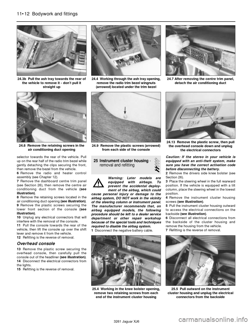
7Remove the dashboard centre trim panel
(see Section 26), then remove the centre air
conditioning duct from the vehicle (see
illustration).
8Remove the retaining screws located in the
air conditioning duct opening (see illustration).
9Remove the plastic screws securing the
lower front section of the console (see
illustration).
10Unplug any electrical connectors that will
interfere with the removal of the console.
11Pull the console towards the rear of the
vehicle, then lift the console up over the shift
lever and remove it from the vehicle.
12Refitting is the reverse of removal.
Overhead console
13Remove the plastic screw securing the
overhead console, then carefully pull the
console out of the headliner (see illustration).
14Disconnect the electrical connectors from
the lights.
15Refitting is the reverse of removal.
25 Instrument cluster housing-
removal and refitting
2
Warning: Later models are
equipped with airbags. To
prevent the accidental deploy-
ment of the airbag, which could
cause personal injury or damage to the
airbag system, DO NOT work in the vicinity
of the steering column or instrument panel.
The manufacturer recommends that, on
airbag equipped models, the following
procedure should be left to a dealer service
department or other repair workshop
because of the special tools and techniques
required to disable the airbag system.
1Disconnect the negative battery cable. Caution: If the stereo in your vehicle is
equipped with an anti-theft system, make
sure you have the correct activation code
before disconnecting the battery.
2Remove the drivers side knee bolster (see
Section 26).
3Place the steering wheel in the full rearward
position. If the vehicle is equipped with a tilt
column, place the steering wheel in the lowest
position.
4Remove the instrument cluster housing
screws (see illustration).
5Pull the instrument cluster housing outward
to access the electrical connections on the
backside (see illustration).
6Disconnect all electrical connections from
the backside of the cluster housing and
remove the housing from the vehicle.
7Refitting is the reverse of removal.
11•12 Bodywork and fittings
24.3b Pull the ash tray towards the rear of
the vehicle to remove it - don’t pull it
straight up24.4 Working through the ash tray opening,
remove the radio trim bezel wingnuts
(arrowed) located under the trim bezel24.7 After removing the centre trim panel,
detach the air conditioning duct
24.8 Remove the retaining screws in the
air conditioning duct opening24.9 Remove the plastic screws (arrowed)
from each side of the console24.13 Remove the plastic screw, then pull
the overhead console down and unplug
the electrical connectors
3261 Jaguar XJ6
25.4 Working in the knee bolster opening,
remove two retaining screws from each
end of the instrument cluster housing25.5 Pull outward on the instrument
cluster housing and unplug the electrical
connectors from the backside
Page 161 of 227
26 Dashboard trim panels-
removal and refitting
2
Warning: Later models are
equipped with airbags. To
prevent the accidental deploy-
ment of the airbag, which could
cause personal injury or damage to the
airbag system, DO NOT work in the vicinity
of the steering column or instrument panel.
The manufacturer recommends that, on
airbag equipped models, the following
procedure should be left to a dealer service
department or other repair workshop
because of the special tools and techniques
required to disable the airbag system.
Caution: If the stereo in your vehicle is
equipped with an anti-theft system, make
sure you have the correct activation code
before disconnecting the battery
Knee bolster
1Knee bolsters are located on the lower half
of the instrument panel on the driver and
passenger sides of the vehicle. The removal of
these covers will allow access to a variety of
electrical, heating and air conditioning
components.
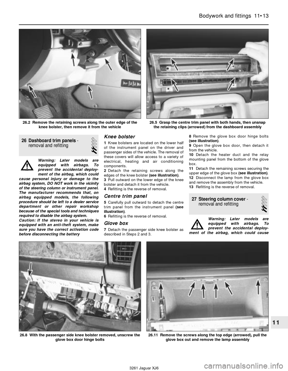
2Detach the retaining screws along the
edges of the knee bolster (see illustration).
3Pull outward on the lower edge of the knee
bolster and detach it from the vehicle.
4Refitting is the reverse of removal.
Centre trim panel
5Carefully pull outward to detach the centre
trim panel from the instrument panel (see
illustration).
6Refitting is the reverse of removal.
Glove box
7Detach the passenger side knee bolster as
described in Steps 2 and 3.8Remove the glove box door hinge bolts
(see illustration).
9Open the glove box door, then detach it
from the vehicle.
10Detach the heater duct and the relay
mounting panel from the bottom of the glove
box.
11Detach the remaining screws securing the
upper edge of the glove box (see illustration).
12Disconnect the lamp from the glove box
and remove the assembly from the vehicle.
13Refitting is the reverse of removal.
27 Steering column cover-
removal and refitting
2
Warning: Later models are
equipped with airbags. To
prevent the accidental deploy-
ment of the airbag, which could cause
Bodywork and fittings 11•13
11
3261 Jaguar XJ6 26.2 Remove the retaining screws along the outer edge of the
knee bolster, then remove it from the vehicle
26.5 Grasp the centre trim panel with both hands, then unsnap
the retaining clips (arrowed) from the dashboard assembly
26.8 With the passenger side knee bolster removed, unscrew the
glove box door hinge bolts26.11 Remove the screws along the top edge (arrowed), pull the
glove box out and remove the lamp assembly
Page 204 of 227

3261 Jaguar XJ6
Use of EnglishREF•3
As the main part of this book has been written in the US, it uses the appropriate US component names, phrases, and spelling. Some of these
differ from those used in the UK. Normally, these cause no difficulty, but to make sure, a glossary is printed below. When ordering spare parts,
remember the parts list may use some of these words:
AMERICAN ENGLISH
Aluminum Aluminium
Antenna Aerial
Authorized Authorised
Auto parts stores Motor factors
Axleshaft Halfshaft
Back-up Reverse
Barrel Choke/venturi
Block Chock
Box-end wrench Ring spanner
Bushing Bush
Carburetor Carburettor
Center Centre
Coast Freewheel
Color Colour
Convertible Drop head coupe
Cotter pin Split pin
Counterclockwise Anti-clockwise
Countershaft (of gearbox) Layshaft
Dashboard Facia
Denatured alcohol Methylated spirit
Dome lamp Interior light
Driveaxle Driveshaft
Driveshaft Propeller shaft
Fender Wing/mudguard
Firewall Bulkhead
Flashlight Torch
Float bowl Float chamber
Floor jack Trolley jack
Freeway, turnpike etc Motorway
Freeze plug Core plug
Frozen Seized
Gas tank Petrol tank
Gasoline (gas) Petrol
Gearshift Gearchange
Generator (DC) Dynamo
Ground (electrical) Earth
Header Exhaust manifold
Heat riser Hot spot
High Top gear
Hood (engine cover) Bonnet
Installation Refitting
Intake Inlet
Jackstands Axle stands
Jumper cable Jump lead
Keeper Collet
Kerosene Paraffin
Knock pin Roll pin
Lash Clearance
Lash Free-play
Latch Catch
Latches Locks
License plate Number plate
Light Lamp
Lock (for valve spring retainer) Split cotter (for valve spring cap)
Lopes Hunts
Lug nut/bolt Wheel nut/bolt
Metal chips or debris Swarf
Misses Misfires
AMERICAN ENGLISH
Muffler Silencer
Odor Odour
Oil pan Sump
Open flame Naked flame
Panel wagon/van Van
Parking brake Handbrake
Parking light Sidelight
Pinging Pinking
Piston pin or wrist pin Gudgeon pin
Piston pin or wrist pin Small end, little end
Pitman arm Drop arm
Power brake booster Servo unit
Primary shoe (of brake) Leading shoe (of brake)
Prussian blue Engineer’s blue
Pry Prise (force apart)
Prybar Lever
Prying Levering
Quarter window Quarterlight
Recap Retread
Release cylinder Slave cylinder
Repair shop Garage
Replacement Renewal
Ring gear (of differential) Crownwheel
Rocker panel (beneath doors) Sill panel (beneath doors)
Rod bearing Big-end bearing
Rotor/disk Disc (brake)
Secondary shoe (of brake) Trailing shoe (of brake)
Sedan Saloon
Setscrew, Allen screw Grub screw
Shock absorber, shock Damper
Snap-ring Circlip
Soft top Hood
Spacer Distance piece
Spare tire Spare wheel
Spark plug wires HT leads
Spindle arm Steering arm
Stabilizer or sway bar Anti-roll bar
Station wagon Estate car
Stumbles Hesitates
Tang or lock Tab washer
Throw-out bearing Thrust bearing
Tie-rod or connecting rod (of steering) Trackrod
Tire Tyre
Transmission Gearbox
Troubleshooting Fault finding/diagnosis
Trunk Boot (luggage compartment)
Turn signal Indicator
TV (throttle valve) cable Kickdown cable
Unpublicized Unpublicised
Valve cover Rocker cover
Valve lifter Tappet
Valve lifter or tappet Cam follower or tappet
Vapor Vapour
Vise Vice
Wheel cover Roadwheel trim
Whole drive line Transmission
Windshield Windscreen
Wrench Spanner
Page 205 of 227
3261 Jaguar XJ6
REF•4Buying spare parts
Spare parts are available from many
sources, including maker’s appointed
garages, accessory shops, and motor factors.
To be sure of obtaining the correct parts, it
will sometimes be necessary to quote the
vehicle identification number. If possible, it
can also be useful to take the old parts along
for positive identification. Items such as
starter motors and alternators may be
available under a service exchange scheme -
any parts returned should be clean.
Our advice regarding spare parts is as
follows.
Officially appointed garages
This is the best source of parts which are
peculiar to your car, and which are not
otherwise generally available (eg, badges,
interior trim, certain body panels, etc). It is
also the only place at which you should buy
parts if the vehicle is still under warranty.
Accessory shops
These are very good places to buy
materials and components needed for themaintenance of your car (oil, air and fuel
filters, light bulbs, drivebelts, greases, brake
pads, touch-up paint, etc). Components of
this nature sold by a reputable shop are
usually of the same standard as those used
by the car manufacturer.
Besides components, these shops also sell
tools and general accessories, usually have
convenient opening hours, charge lower
prices, and can often be found close to home.
Some accessory shops have parts counters
where components needed for almost any
repair job can be purchased or ordered.
Motor factors
Good factors will stock all the more
important components which wear out
comparatively quickly, and can sometimes
supply individual components needed for the
overhaul of a larger assembly (eg, brake seals
and hydraulic parts, bearing shells, pistons,
valves). They may also handle work such as
cylinder block reboring, crankshaft regrinding,
etc.
Tyre and exhaust specialists
These outlets may be independent, or
members of a local or national chain. They
frequently offer competitive prices when
compared with a main dealer or local garage,
but it will pay to obtain several quotes before
making a decision. When researching prices,
also ask what “extras” may be added - for
instance fitting a new valve and balancing the
wheel are both commonly charged on top of
the price of a new tyre.
Other sources
Beware of parts or materials obtained from
market stalls, car boot sales or similar outlets.
Such items are not invariably sub-standard,
but there is little chance of compensation if
they do prove unsatisfactory. In the case of
safety-critical components such as brake
pads, there is the risk of financial loss, and
also of an accident causing injury or death.
Second-hand parts or assemblies obtained
from a car breaker can be a good buy in some
circumstances, but this sort of purchase is
best made by the experienced DIY mechanic.
Vehicle identification
Modifications are a continuing and
unpublicised process in vehicle manufacture,
quite apart from major model changes. Spare
parts manuals and lists are compiled upon a
numerical basis, the individual vehicle
identification numbers being essential to
correct identification of the part concerned.
When ordering spare parts, always give as
much information as possible. Quote the car
model, year of manufacture and registration,
chassis and engine numbers as appropriate.
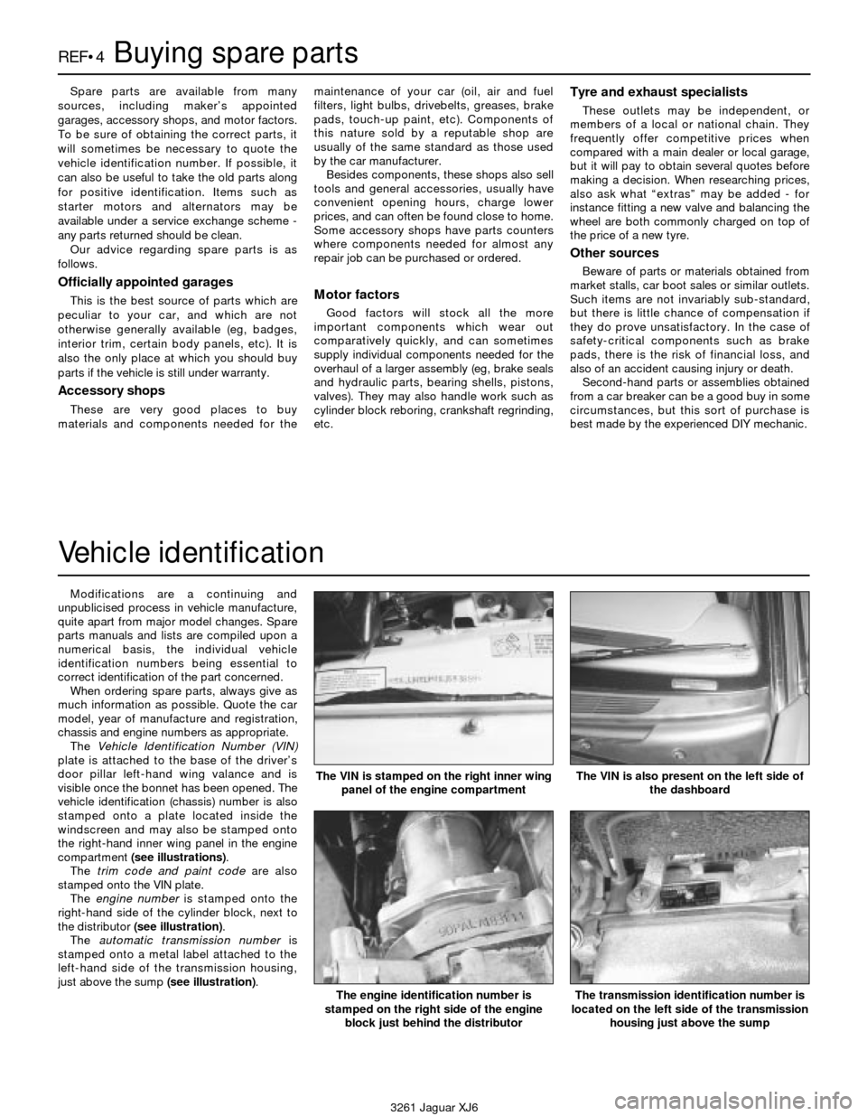
The Vehicle Identification Number (VIN)
plate is attached to the base of the driver’s
door pillar left-hand wing valance and is
visible once the bonnet has been opened. The
vehicle identification (chassis) number is also
stamped onto a plate located inside the
windscreen and may also be stamped onto
the right-hand inner wing panel in the engine
compartment (see illustrations).
The trim code and paint codeare also
stamped onto the VIN plate.
The engine numberis stamped onto the
right-hand side of the cylinder block, next to
the distributor (see illustration).
The automatic transmission numberis
stamped onto a metal label attached to the
left-hand side of the transmission housing,
just above the sump (see illustration).The VIN is stamped on the right inner wing
panel of the engine compartment
The engine identification number is
stamped on the right side of the engine
block just behind the distributorThe transmission identification number is
located on the left side of the transmission
housing just above the sump
The VIN is also present on the left side of
the dashboard
Page 223 of 227

3261 Jaguar XJ6
REF•22Index
AABS fault finding -9•2
Accelerator cable -4•8
Acknowledgements -0•4
Aerial - 12•8
Air cleaner -1•14, 4•7
Air conditioning -3•2, 3•7, 3•10, 3•11, 3•13, 3•14
Air induction system -4•9
Air Injector Reactor (AIR) system -6•8
Air intake plenum -4•13
Airbag - 0•5, 12•14
Alternator -5•6
Amplifier -5•3
Anti-lock Brake system (ABS) -9•2
Anti-roll bar - 10•3
Anti-theft system - REF•1
Antifreeze -0•11, 0•16, 1•2, 1•20, 3•2
Asbestos -0•5
ATF -0•16
Automatic transmission-7•1et seq
fault finding - 7•1, REF•15
fluid - 0•16, 1•2, 1•11, 1•19
filter - 1•19
Auxiliary shaft -2A•8
BBalljoints - 10•4
Battery -0•5, 0•15, 1•9, 5•1, 5•1
Big-end bearings -2B•13, 2B•17
Bleeding
brake system - 9•10
power steering - 10•11
Block -2B•10, 2B•11
Blower motors -3•7
Body corrosion - REF•11
Body electrical system- 12•1et seq
Bodywork and fittings- 11•1et seq
Bonnet - 11•3, 11•4
Boot - 11•7
lid - 11•3, 11•6, 11•7,
Boots (steering) - 10•9
Brake fluid -0•12, 0•16, 1•20
Brake lights - 12•12
switch - 9•13
Brake servo -1•12
Braking system-1•12, 9•1et seq
fault finding - REF•15, REF•16
MOT checks - REF•8 to REF•10
Bulbs -0•15, 12•11
Bumpers - 11•5
Burning -0•5
CCables -4•8, 5•2, 7•2, 7•4, 9•10, 9•11, 11•4, 11•10
Calipers -9•3
Camshafts -2A•9
Capacities -1•2
Carpets - 11•1
Cassette - REF•1
Catalytic converter -6•12
Central locking - 12•13
Centre console - 11•11
Charcoal canister -6•11
Charging -1•10
Charging system -5•5
Circuit breakers - 12•3
CO emissions (mixture) - REF•11
Coil (HT) -5•3
Coil spring - 10•5, 10•6
Compression check -2B•3
Compressor -3•13
Condenser -3•13
Connecting rods -2B•9, 2B•12, 2B•17, 2B•18
Console - 11•11, 11•12
Continuity check - 12•2
Control arms - 10•5, 10•6, 10•8
Conversion factors - REF•2
Coolant -0•11, 0•16, 1•2, 1•20, 3•2
Coolant reservoir -3•4, 3•5
Coolant temperature sensor -6•3
Cooling fans -3•3
Cooling system fault finding - REF•14
Cooling,heating and air conditioning systems-3•1et seq
Courtesy lights - 12•12
Cowl cover - 11•14
Crankcase ventilation system -1•16, 6•11
Crankshaft -2A•5, 2A•17, 2B•10, 2B•13, 2B•16
position sensor - 6•7
Cruise control - 12•13
Crushing -0•5
Cylinder head -2A•13, 2B•6, 2B•7, 2B•8
Cylinder honing -2B•12
DDashboard - 11•13
Dents - 11•2
Differential -8•1, 8•5
oil - 1•2, 1•11, 1•20
Dimensions - REF•1
Direction indicators - 12•4, 12•11, 12•12
Discs -9•4
Distributor -5•4
Doors - 11•7, 11•8, 11•9, 11•10, 11•10, REF•9
Drivebelt -1•16
Driveplate -2A•16
Driveshafts -8•1, 8•4, 8•5, REF•10
Drivetrain-1•14, 8•1et seq
Note:References throughout this index are in the form - “Chapter number” • “page number”