oil temperature JAGUAR XJ6 1997 2.G User Guide
[x] Cancel search | Manufacturer: JAGUAR, Model Year: 1997, Model line: XJ6, Model: JAGUAR XJ6 1997 2.GPages: 227, PDF Size: 7.2 MB
Page 78 of 227
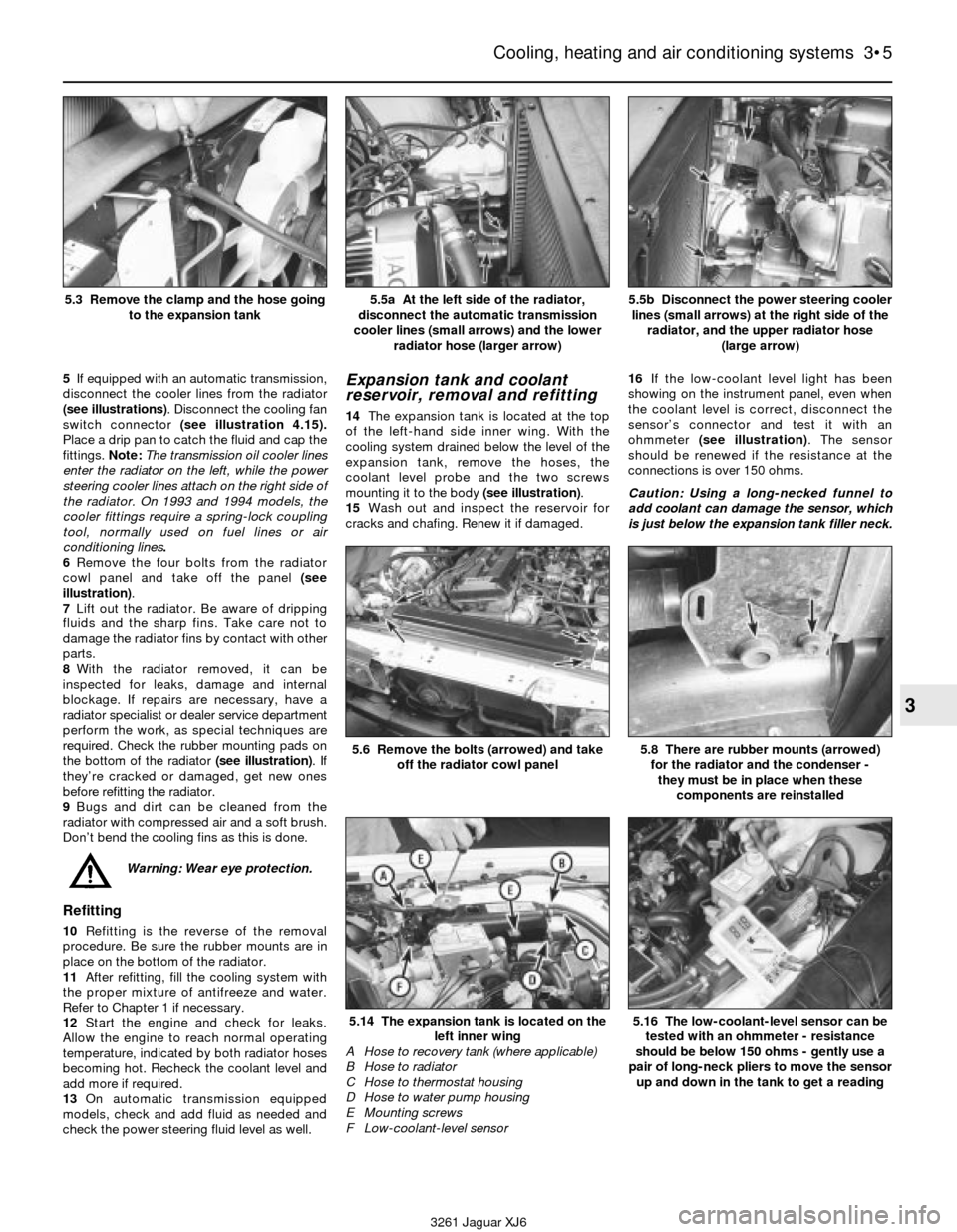
5If equipped with an automatic transmission,
disconnect the cooler lines from the radiator
(see illustrations). Disconnect the cooling fan
switch connector (see illustration 4.15).
Place a drip pan to catch the fluid and cap the
fittings. Note:The transmission oil cooler lines
enter the radiator on the left, while the power
steering cooler lines attach on the right side of
the radiator. On 1993 and 1994 models, the
cooler fittings require a spring-lock coupling
tool, normally used on fuel lines or air
conditioning lines.
6Remove the four bolts from the radiator
cowl panel and take off the panel (see
illustration).
7Lift out the radiator. Be aware of dripping
fluids and the sharp fins. Take care not to
damage the radiator fins by contact with other
parts.
8With the radiator removed, it can be
inspected for leaks, damage and internal
blockage. If repairs are necessary, have a
radiator specialist or dealer service department
perform the work, as special techniques are
required. Check the rubber mounting pads on
the bottom of the radiator (see illustration). If
they’re cracked or damaged, get new ones
before refitting the radiator.
9Bugs and dirt can be cleaned from the
radiator with compressed air and a soft brush.
Don’t bend the cooling fins as this is done.
Warning: Wear eye protection.
Refitting
10Refitting is the reverse of the removal
procedure. Be sure the rubber mounts are in
place on the bottom of the radiator.
11After refitting, fill the cooling system with
the proper mixture of antifreeze and water.
Refer to Chapter 1 if necessary.
12Start the engine and check for leaks.
Allow the engine to reach normal operating
temperature, indicated by both radiator hoses
becoming hot. Recheck the coolant level and
add more if required.
13On automatic transmission equipped
models, check and add fluid as needed and
check the power steering fluid level as well.
Expansion tank and coolant
reservoir, removal and refitting
14The expansion tank is located at the top
of the left-hand side inner wing. With the
cooling system drained below the level of the
expansion tank, remove the hoses, the
coolant level probe and the two screws
mounting it to the body (see illustration).
15Wash out and inspect the reservoir for
cracks and chafing. Renew it if damaged.16If the low-coolant level light has been
showing on the instrument panel, even when
the coolant level is correct, disconnect the
sensor’s connector and test it with an
ohmmeter (see illustration). The sensor
should be renewed if the resistance at the
connections is over 150 ohms.
Caution: Using a long-necked funnel to
add coolant can damage the sensor, which
is just below the expansion tank filler neck.
Cooling, heating and air conditioning systems 3•5
3
5.5a At the left side of the radiator,
disconnect the automatic transmission
cooler lines (small arrows) and the lower
radiator hose (larger arrow)5.5b Disconnect the power steering cooler
lines (small arrows) at the right side of the
radiator, and the upper radiator hose
(large arrow)
3261 Jaguar XJ6 5.3 Remove the clamp and the hose going
to the expansion tank
5.6 Remove the bolts (arrowed) and take
off the radiator cowl panel
5.14 The expansion tank is located on the
left inner wing
A Hose to recovery tank (where applicable)
B Hose to radiator
C Hose to thermostat housing
D Hose to water pump housing
E Mounting screws
F Low-coolant-level sensor
5.8 There are rubber mounts (arrowed)
for the radiator and the condenser -
they must be in place when these
components are reinstalled
5.16 The low-coolant-level sensor can be
tested with an ohmmeter - resistance
should be below 150 ohms - gently use a
pair of long-neck pliers to move the sensor
up and down in the tank to get a reading
Page 79 of 227

17A coolant recovery bottle is used on 1988
and 1989 models, located in the passenger’s
inner wing. The plastic inner wing splash
shield must be removed for access to the
recovery bottle (see Chapter 11). Disconnect
the recovery hose and remove the mounting
screws to renew the recovery bottle (see
illustration). Models from 1990 on do not
have the recovery bottle, but do have a larger
expansion tank.
18Refitting of either expansion tank or
recovery bottle is the reverse of removal.
6 Engine oil cooler- renewal
2
1Models from 1988 through 1991 have a
engine oil cooler, mounted ahead of the
radiator. The engine’s mechanical fan draws
air through the oil cooler, cooling off hot
engine oil that is circulated from the engine by
steel tubes. Access to the cooler is with the
grille removed (refer to Chapter 11 for grille
removal).
2To renew the oil cooler, first disconnect thetwo fittings connecting the lines to the cooler
(see illustration).
Caution: The engine should be cool for this
procedure, and you should have a small
drain pan handy because the fittings are
on the bottom of the cooler and will
probably drip some oil on dismantling.
3Remove the mounting nuts to take the
cooler out of the vehicle (see illustration).
4The other ends of the oil cooler tubes
mount to a block just below the oil filter. With
a drain pan handy, remove the nut retaining
both pipes to the block.
5Refitting the oil cooler and oil lines is the
reverse of removal. When refitting the lines to
the block or the cooler, use new O-rings.7 Water pump- check
1
1A failure in the water pump can cause
serious engine damage due to overheating.
2With the engine running and warmed to
normal operating temperature, squeeze the
upper radiator hose. If the water pump is
working properly, a pressure surge should be
felt as the hose is released.
Warning: Keep hands away from
fan blades!
3Water pumps are equipped with weep or
vent holes (see illustration). If a failure occurs
in the pump seal, coolant will leak from this
hole. In most cases it will be necessary to use
a flashlight to find the hole on the water pump
by looking through the space behind the
pulley just below the water pump shaft.
4If the water pump shaft bearings fail there
may be a howling sound at the front of the
engine while it is running. Bearing wear can be
felt if the water pump pulley is rocked up anddown. Do not mistake drivebelt slippage,
which causes a squealing sound, for water
pump failure. Spray automotive drivebelt
dressing on the belts to eliminate the belt as a
possible cause of the noise.
8 Water pump and pipes-
renewal
3
Warning: Do not start this
procedure until the engine is
completely cool.
1Disconnect the negative battery cable and
drain the cooling system (see Chapter 1).
Caution: If the stereo in your vehicle is
equipped with an anti-theft system, make
sure you have the correct activation code
before disconnecting the battery.
2Refer to Section 4 to remove the
mechanical fan and clutch (if applicable to
your model).
3Refer to Chapter 1 for removal of the
drivebelts.
3•6 Cooling, heating and air conditioning systems
6.3 Remove the mounting nuts (arrowed)
to take the oil cooler out
7.3 Check the weep hole (arrowed) for
signs of leakage (pump removed for
clarity) - grey discolouration is normal,
large brown stains indicates seal failure
3261 Jaguar XJ6 5.17 The recovery bottle (arrowed) on 1988 and 1989 models is
located in the footwell - disconnect the hoses and the two
mounting screws
6.2 Disconnect the two metal oil lines (arrowed) where they
mount to the bottom of the cooler - use two spanners
Page 84 of 227
4Refitting is the reverse of the removal
procedure.
5Run the engine and check for proper
functioning of the heater (and air conditioning,
if equipped).
Control checks
6The climate-control system uses an all-
electronic control panel that sends digital
information to the climate control computer.
There is little the home mechanic can do to
troubleshoot or test the system. The factory
recommends that diagnosis be performed at a
dealership.
7If there is a problem in just one area of
climate control, put the controls through their
entire range of operation and check the
system responses, i.e. set the controls to
COLD, the fan to low and the temperature to
65° F. In this mode the Manual LED should be
lit and the air conditioning compressor should
engage. Try all of the fan speeds and try the
temperature on HOT, then feel for warm air
coming from the ducts. Note:Between each
try of the different controls, wait 20 seconds or
so for the heater/air conditioning system to
adjust before checking for a response.
8When each control button is pushed two
times, its LED light should go on or off. Renew
the control assembly if any of the warning
lights don’t work.
9On 1988 and 1989 models, if the climate
controls do not respond to any driver input,
check with your Jaguar dealer before
renewing the ECU or control panel. A service
part is available (a resistor, #JLM 1901) that
can be installed at one of the control panel
terminals that may fix the problem without any
other parts being renewed. Instructions are
included with the part.
10Check the vacuum lines to the several
vacuum motors that operate the heater/air
conditioning functions. Look for pinched or
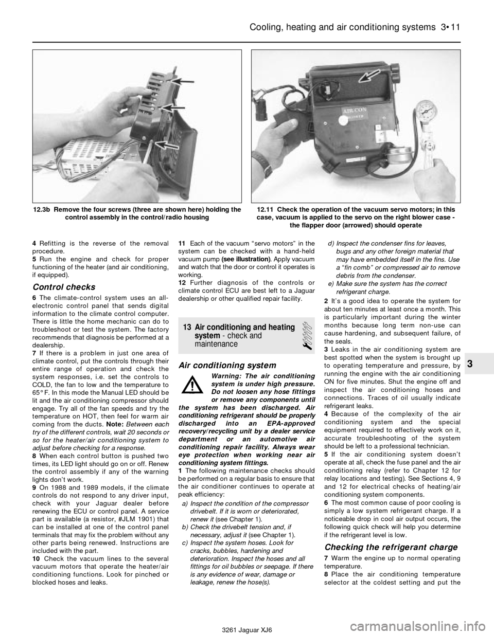
blocked hoses and leaks.11Each of the vacuum “servo motors” in the
system can be checked with a hand-held
vacuum pump (see illustration). Apply vacuum
and watch that the door or control it operates is
working.
12Further diagnosis of the controls or
climate control ECU are best left to a Jaguar
dealership or other qualified repair facility.
13 Air conditioning and heating
system- check and
maintenance
1
Air conditioning system
Warning: The air conditioning
system is under high pressure.
Do not loosen any hose fittings
or remove any components until
the system has been discharged. Air
conditioning refrigerant should be properly
discharged into an EPA-approved
recovery/recycling unit by a dealer service
department or an automotive air
conditioning repair facility. Always wear
eye protection when working near air
conditioning system fittings.
1The following maintenance checks should
be performed on a regular basis to ensure that
the air conditioner continues to operate at
peak efficiency:
a) Inspect the condition of the compressor
drivebelt. If it is worn or deteriorated,
renew it (see Chapter 1).
b) Check the drivebelt tension and, if
necessary, adjust it (see Chapter 1).
c) Inspect the system hoses. Look for
cracks, bubbles, hardening and
deterioration. Inspect the hoses and all
fittings for oil bubbles or seepage. If there
is any evidence of wear, damage or
leakage, renew the hose(s).d) Inspect the condenser fins for leaves,
bugs and any other foreign material that
may have embedded itself in the fins. Use
a “fin comb” or compressed air to remove
debris from the condenser.
e) Make sure the system has the correct
refrigerant charge.
2It’s a good idea to operate the system for
about ten minutes at least once a month. This
is particularly important during the winter
months because long term non-use can
cause hardening, and subsequent failure, of
the seals.
3Leaks in the air conditioning system are
best spotted when the system is brought up
to operating temperature and pressure, by
running the engine with the air conditioning
ON for five minutes. Shut the engine off and
inspect the air conditioning hoses and
connections. Traces of oil usually indicate
refrigerant leaks.
4Because of the complexity of the air
conditioning system and the special
equipment required to effectively work on it,
accurate troubleshooting of the system
should be left to a professional technician.
5If the air conditioning system doesn’t
operate at all, check the fuse panel and the air
conditioning relay (refer to Chapter 12 for
relay locations and testing). See Sections 4, 9
and 12 for electrical checks of heating/air
conditioning system components.
6The most common cause of poor cooling is
simply a low system refrigerant charge. If a
noticeable drop in cool air output occurs, the
following quick check will help you determine
if the refrigerant level is low.
Checking the refrigerant charge
7Warm the engine up to normal operating
temperature.
8Place the air conditioning temperature
selector at the coldest setting and put the
Cooling, heating and air conditioning systems 3•11
3
3261 Jaguar XJ6 12.3b Remove the four screws (three are shown here) holding the
control assembly in the control/radio housing
12.11 Check the operation of the vacuum servo motors; in this
case, vacuum is applied to the servo on the right blower case -
the flapper door (arrowed) should operate
Page 101 of 227
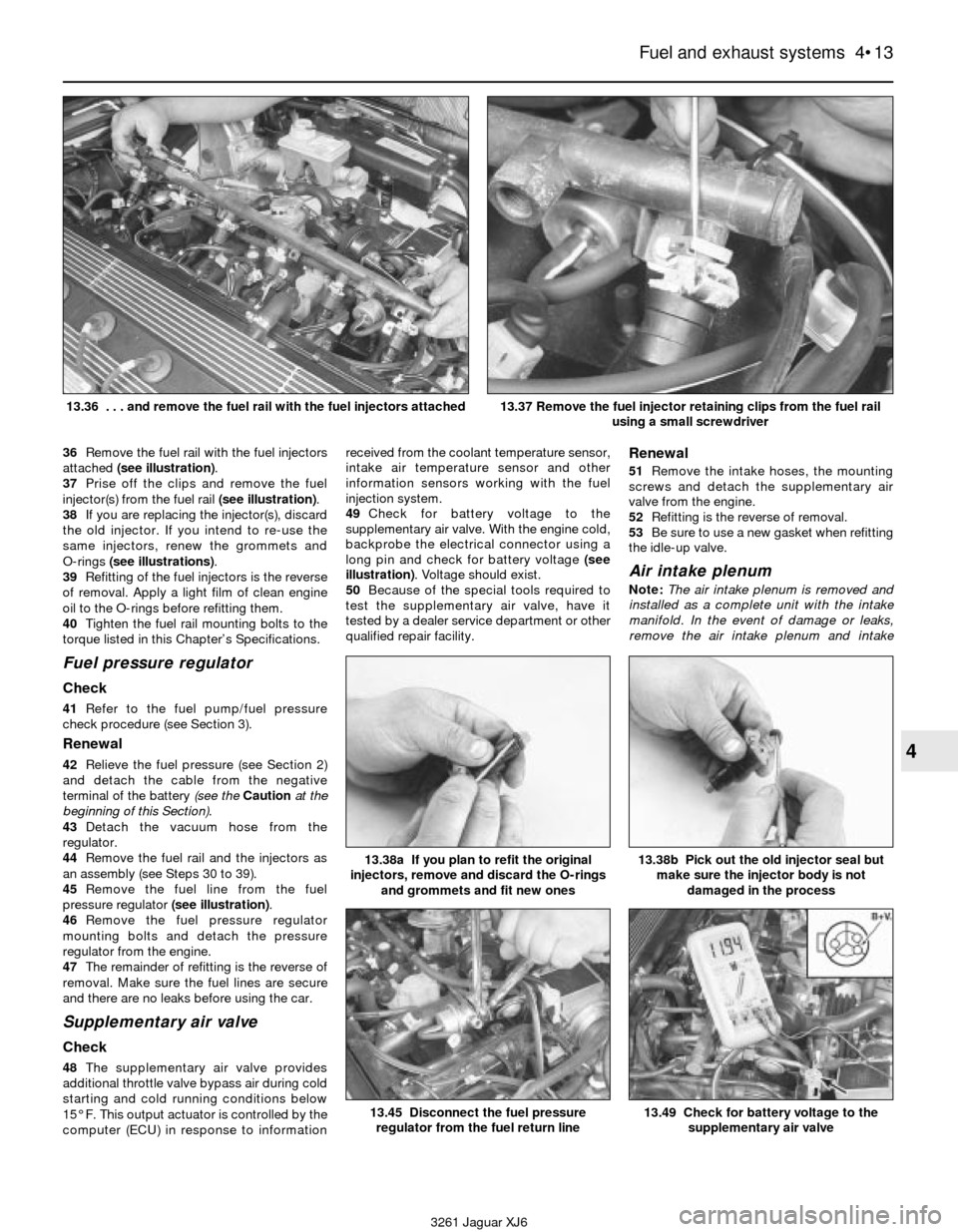
36Remove the fuel rail with the fuel injectors
attached (see illustration).
37Prise off the clips and remove the fuel
injector(s) from the fuel rail (see illustration).
38If you are replacing the injector(s), discard
the old injector. If you intend to re-use the
same injectors, renew the grommets and
O-rings (see illustrations).
39Refitting of the fuel injectors is the reverse
of removal. Apply a light film of clean engine
oil to the O-rings before refitting them.
40Tighten the fuel rail mounting bolts to the
torque listed in this Chapter’s Specifications.
Fuel pressure regulator
Check
41Refer to the fuel pump/fuel pressure
check procedure (see Section 3).
Renewal
42Relieve the fuel pressure (see Section 2)
and detach the cable from the negative
terminal of the battery (see the Cautionat the
beginning of this Section).
43Detach the vacuum hose from the
regulator.
44Remove the fuel rail and the injectors as
an assembly (see Steps 30 to 39).
45Remove the fuel line from the fuel
pressure regulator (see illustration).
46Remove the fuel pressure regulator
mounting bolts and detach the pressure
regulator from the engine.
47The remainder of refitting is the reverse of
removal. Make sure the fuel lines are secure
and there are no leaks before using the car.
Supplementary air valve
Check
48The supplementary air valve provides
additional throttle valve bypass air during cold
starting and cold running conditions below
15° F. This output actuator is controlled by the
computer (ECU) in response to informationreceived from the coolant temperature sensor,
intake air temperature sensor and other
information sensors working with the fuel
injection system.
49Check for battery voltage to the
supplementary air valve. With the engine cold,
backprobe the electrical connector using a
long pin and check for battery voltage (see
illustration). Voltage should exist.
50Because of the special tools required to
test the supplementary air valve, have it
tested by a dealer service department or other
qualified repair facility.
Renewal
51Remove the intake hoses, the mounting
screws and detach the supplementary air
valve from the engine.
52Refitting is the reverse of removal.
53Be sure to use a new gasket when refitting
the idle-up valve.
Air intake plenum
Note:The air intake plenum is removed and
installed as a complete unit with the intake
manifold. In the event of damage or leaks,
remove the air intake plenum and intake
Fuel and exhaust systems 4•13
4
3261 Jaguar XJ6 13.36 . . . and remove the fuel rail with the fuel injectors attached
13.37 Remove the fuel injector retaining clips from the fuel rail
using a small screwdriver
13.45 Disconnect the fuel pressure
regulator from the fuel return line
13.38b Pick out the old injector seal but
make sure the injector body is not
damaged in the process13.38a If you plan to refit the original
injectors, remove and discard the O-rings
and grommets and fit new ones
13.49 Check for battery voltage to the
supplementary air valve
Page 104 of 227
same dimensions, amperage rating, cold
cranking rating, etc. as the original.
6Refitting is the reverse of removal.
4 Battery cables-
check and renewal
1
Caution: If the stereo in your vehicle is
equipped with an anti-theft system, make
sure you have the correct activation code
before disconnecting the battery.
1Periodically inspect the entire length of
each battery cable for damage, cracked or
burned insulation and corrosion. Poor battery
cable connections can cause starting
problems and decreased engine performance.
2Check the cable-to-terminal connections at
the ends of the cables for cracks, loose wire
strands and corrosion. The presence of white,
fluffy deposits under the insulation at the
cable terminal connection is a sign that the
cable is corroded and should be renewed.
Check the terminals for distortion, missing
mounting bolts and corrosion.
3When removing the cables, always
disconnect the negative cable first and hook it
up last or the battery may be shorted by the
tool used to loosen the cable clamps. Even if
only the positive cable is being renewed, be
sure to disconnect the negative cable from
the battery first (see Chapter 1 for further
information regarding battery cable removal).
4Disconnect the cables from the battery,
then trace each of them to their opposite ends
and detach them from the starter solenoid
and earth terminals. Note the routing of each
cable to ensure correct refitting.
5If you are replacing either or both of the old
cables, take them with you when buying new
items. It is vitally important that you replace
the cables with identical parts. Cables have
characteristics that make them easy to
identify: positive cables are usually red, larger
in cross-section and have a larger diameter
battery post clamp; earth cables are usually
black, smaller in cross-section and have a
slightly smaller diameter clamp for the
negative post.
6Clean the threads of the solenoid or earth
connection with a wire brush to remove rust
and corrosion. Apply a light coat of battery
terminal corrosion inhibitor, or petroleum jelly,
to the threads to prevent future corrosion.
7Attach the cable to the solenoid or earth
connection and tighten the mounting nut/bolt
securely.
8Before connecting a new cable to the
battery, make sure that it reaches the battery
post without having to be stretched.
9Connect the positive cable first, followed by
the negative cable.
5 Ignition system- general
information and precautions
1All models are equipped with a computerised
ignition system. The ignition system consists of
the ignition coil, the crankshaft position sensor,
the amplifier and the electronic control unit
(ECU). The ignition ECU controls the ignition
timing and advance characteristics for the
engine. The ignition timing is not adjustable,
therefore, changing the position of the distributor
will not change the timing in any way. Note:In
the event the distributor must be removed from
the engine, be sure to follow the precautions
described in Section 9 and mark the engine and
distributor with paint to ensure correct refitting. If
the distributor is not marked and Ihe crankshaft is
turned while the distributor is out of the engine,
have the distributor installed by a dealer service
department. The distributor must be installed
using a special alignment tool.
2The distributor is driven by the intermediate
shaft which also drives the power steering pump.
The crankshaft position sensor is located on the
front timing cover. It detects crank position by
pulsing an electronic signal to the ECU. This
signal is sent to the ECU to provide ignition
timing specifications.
3The computerised ignition system provides
complete control of the ignition timing by
determining the optimum timing in response to
engine speed, coolant temperature, throttle
position and vacuum pressure in the intake
manifold. These parameters are relayed to the
ECU by the crankshaft position sensor, throttle
potentiometer, coolant temperature sensor and
MAF sensor. Ignition timing is altered during
warm-up, idling and warm running conditions by
the ECU. This electronic ignition system also
consists of the ignition switch, battery, coil,
distributor, spark plug leads and spark plugs.
4Refer to a dealer parts department or car
accessory outlet for any questions concerning
the availability of the distributor parts and
assemblies. Testing the crankshaft position
sensor is covered in Chapter 6.
5When working on the ignition system, take
the following precautions:
a) Do not keep the ignition switch on for
more than 10 seconds if the engine will
not start.
b) Always connect a tachometer in
accordance with the manufacturer’s
instructions. Some tachometers may be
incompatible with this ignition system.
Consult a dealer service department
before buying a tachometer for use with
this vehicle.
c) Never allow the ignition coil terminals to
touch earth. Earthing the coil could result
in damage to the igniter and/or the
ignition coil.
d) Do not disconnect the battery when the
engine is running.
6 Ignition system- check
2
Warning: Because of the high
voltage generated by the
ignition system, extreme care
should be taken when working
on the ignition components. This not only
includes the amplifier, coil, distributor and
spark plug leads, but related components
such as connectors, tachometer and other
test equipment also.
1With the ignition switch turned to the “ON”
position, a “Battery” light or an “Oil Pressure”
light is a basic check for ignition and battery
supply to the ECU.
2Check all ignition wiring connections for
tightness, cuts, corrosion or any other signs of a
bad connection.
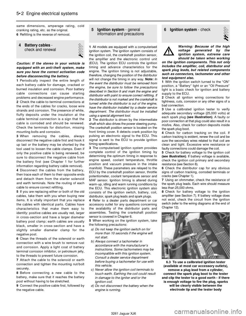
3Use a calibrated ignition tester to verify
adequate secondary voltage (25,000 volts) at
each spark plug (see illustration). A faulty or
poor connection at that plug could also result in a
misfire. Also, check for carbon deposits inside
the spark plug boot.
4Check for carbon tracking on the coil. If
carbon tracking is evident, renew the coil and be
sure the secondary wires related to that coil are
clean and tight. Excessive wire resistance or
faulty connections could damage the coil.
5Check for battery voltage to the ignition coil
(see illustration). If battery voltage is available,
check the ignition coil primary and secondary
resistance (see Section 8).
6Check the distributor cap for any obvious
signs of carbon tracking, corroded terminals or
cracks (see Chapter 1).
7Using an ohmmeter, check the resistance of
the spark plug leads. Each wire should measure
less than 25,000 ohms.
8Check for battery voltage to the ignition
amplifier (see Section 7). If battery voltage does
not exist, check the circuit from the ignition
switch (refer to the wiring diagrams at the end of
Chapter 12).
5•2 Engine electrical systems
6.3 To use a calibrated ignition tester
(available at most car accessory outlets),
remove a plug lead from a cylinder,
connect the spark plug boot to the tester
and clip the tester to a good earth - if there
is enough voltage to fire the plug, sparks
will be clearly visible between the
electrode tip and the tester body
3261 Jaguar XJ6
Page 109 of 227
8After the alternator is installed, adjust the
drivebelt tension (see Chapter 1).
9Check the charging voltage to verify proper
operation of the alternator (see Section 11).
13 Starting system- general
information and precautions
The sole function of the starting system is
to crank the engine over quickly enough to
allow it to start.
The starting system consists of the battery,
the starter motor, the starter solenoid, the
starter relay and the electrical circuit
connecting the components. The solenoid is
mounted directly on the starter motor.
The solenoid/starter motor assembly is
installed on the upper part of the engine, next
to the transmission bellhousing.
When the ignition key is turned to the
START position, the starter solenoid is
actuated through the starter control circuit.
The starter solenoid then connects the battery
to the starter. The battery supplies the
electrical energy to the starter motor, which
does the actual work of cranking the engine.
The starter on a vehicle equipped with an
automatic transmission can be operated only
when the transmission selector lever is in Park
or Neutral.
These vehicles are equipped with either a
Bosch or Lucas starter assembly. The Lucas
unit is distinguished by the separate earth
strap from the solenoid to the starter body.
Bosch starter assemblies are equipped with a
solid metal earthing bar.
The starting system circuit is equipped with
a relay. The relay allows the ignition switch to
power the starter solenoid.
Always observe the following precautions
when working on the starting system:
a) Excessive cranking of the starter motor
can overheat it and cause serious
damage. Never operate the starter motor
for more than 15 seconds at a time
without pausing to allow it to cool for at
least two minutes.
b) The starter is connected directly to the
battery and could arc or cause a fire if
mishandled, overloaded or short circuited.
c) Always detach the cable from the
negative terminal of the battery before
working on the starting system.
Caution:If the stereo in your vehicle is
equipped with an anti-theft system, make
sure you have the correct activation code
before disconnecting the battery.
14 Starter motor-
testing in vehicle
2
1Make sure that the battery is charged and
that all cables, both at the battery and starter
solenoid terminals, are clean and secure.2If the starter motor does not turn at all when
the switch is operated, make sure that the
shift lever is in Neutral or Park (automatic
transmission) or that the clutch pedal is
depressed (manual transmission).
3If the starter motor spins but the engine is
not cranking, the overrunning clutch in the
starter motor is slipping and the starter motor
must be renewed.
4If, when the switch is actuated, the starter
motor does not operate at all but the solenoid
clicks, then the problem lies with either the
battery, the main solenoid contacts or the
starter motor itself (or the engine is seized).
5If the solenoid plunger cannot be heard
when the switch is actuated, the battery is
bad, the in-line fuse is burned (the circuit is
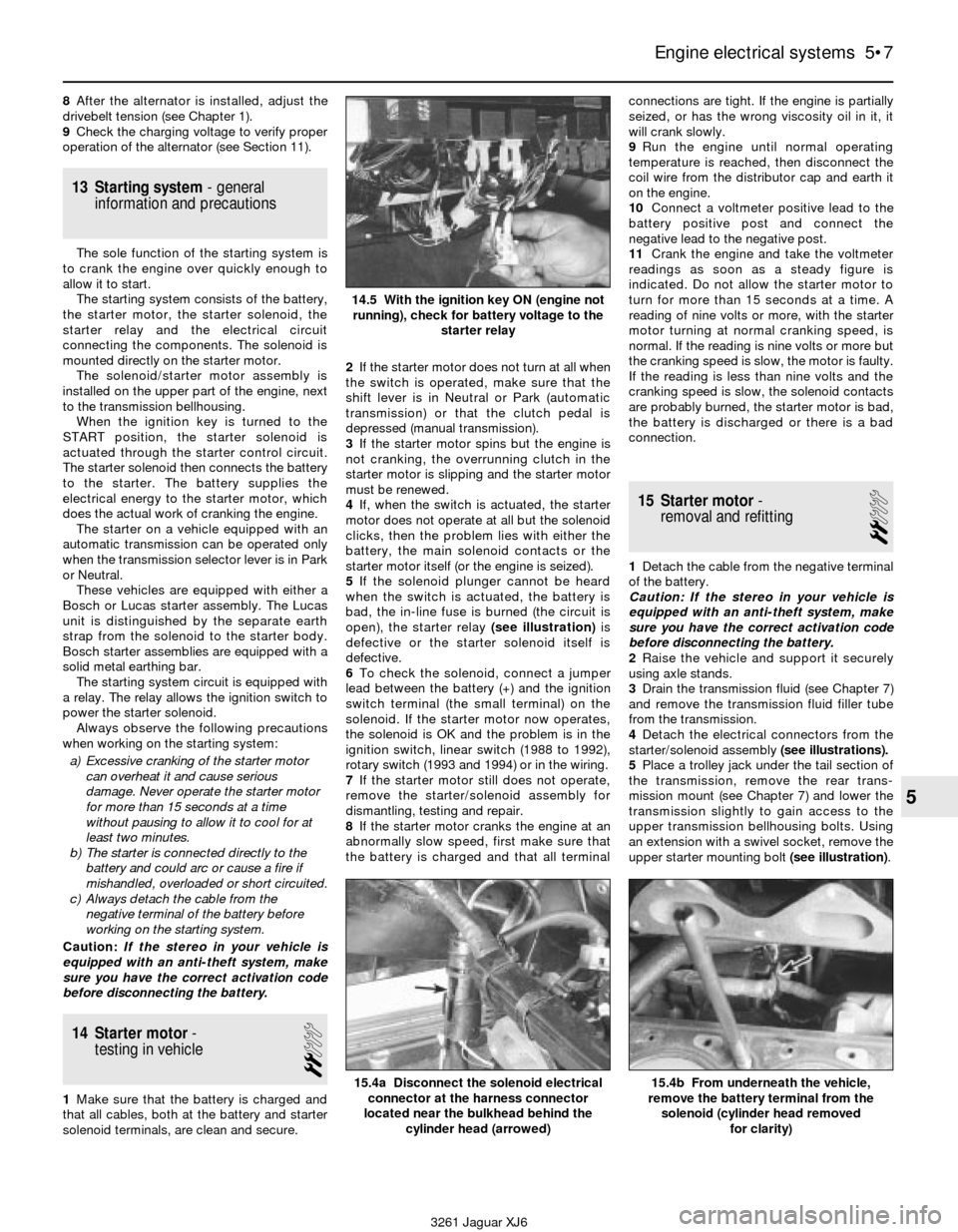
open), the starter relay (see illustration)is
defective or the starter solenoid itself is
defective.
6To check the solenoid, connect a jumper
lead between the battery (+) and the ignition
switch terminal (the small terminal) on the
solenoid. If the starter motor now operates,
the solenoid is OK and the problem is in the
ignition switch, linear switch (1988 to 1992),
rotary switch (1993 and 1994) or in the wiring.
7If the starter motor still does not operate,
remove the starter/solenoid assembly for
dismantling, testing and repair.
8If the starter motor cranks the engine at an
abnormally slow speed, first make sure that
the battery is charged and that all terminalconnections are tight. If the engine is partially
seized, or has the wrong viscosity oil in it, it
will crank slowly.
9Run the engine until normal operating
temperature is reached, then disconnect the
coil wire from the distributor cap and earth it
on the engine.
10Connect a voltmeter positive lead to the
battery positive post and connect the
negative lead to the negative post.
11Crank the engine and take the voltmeter
readings as soon as a steady figure is
indicated. Do not allow the starter motor to
turn for more than 15 seconds at a time. A
reading of nine volts or more, with the starter
motor turning at normal cranking speed, is
normal. If the reading is nine volts or more but
the cranking speed is slow, the motor is faulty.
If the reading is less than nine volts and the
cranking speed is slow, the solenoid contacts
are probably burned, the starter motor is bad,
the battery is discharged or there is a bad
connection.
15 Starter motor-
removal and refitting
2
1Detach the cable from the negative terminal
of the battery.
Caution: If the stereo in your vehicle is
equipped with an anti-theft system, make
sure you have the correct activation code
before disconnecting the battery.
2Raise the vehicle and support it securely
using axle stands.
3Drain the transmission fluid (see Chapter 7)
and remove the transmission fluid filler tube
from the transmission.
4Detach the electrical connectors from the
starter/solenoid assembly (see illustrations).
5Place a trolley jack under the tail section of
the transmission, remove the rear trans-
mission mount (see Chapter 7) and lower the
transmission slightly to gain access to the
upper transmission bellhousing bolts. Using
an extension with a swivel socket, remove the
upper starter mounting bolt (see illustration).
Engine electrical systems 5•7
5
14.5 With the ignition key ON (engine not
running), check for battery voltage to the
starter relay
15.4a Disconnect the solenoid electrical
connector at the harness connector
located near the bulkhead behind the
cylinder head (arrowed)15.4b From underneath the vehicle,
remove the battery terminal from the
solenoid (cylinder head removed
for clarity)
3261 Jaguar XJ6
Page 113 of 227
2The CHECK ENGINE warning light, which is
located on the instrument panel, comes on
when the ignition switch is turned to ON and
the engine is not running. When the engine is
started, the warning light should go out. If the
light remains on, the self-diagnosis system
has detected a malfunction. Note: The
CHECK ENGINE light on early models is
displayed on the dashboard VCM panel on the
right side. Later models are equipped with a
separate CHECK ENGINE light on the left side
of the instrument cluster.Note:Not all the
codes will cause the CHECK ENGINE light to
activate. When performing any fuel or
emissions systems diagnosis, always check
for codes that may be stored but not indicated
by the CHECK ENGINE light.
Obtaining fault code output
3To obtain an output of diagnostic codes,
verify first that the battery voltage is above 11
volts, the throttle is fully closed, the
transmission is in Park, the accessory
switches are off and the engine is at normal
operating temperature.
4Turn the ignition switch to ON but don’t
start the engine (Position II). Note:On 1988
and 1989 models, remember to turn the
ignition switch to position II without turning
the key to OFF.
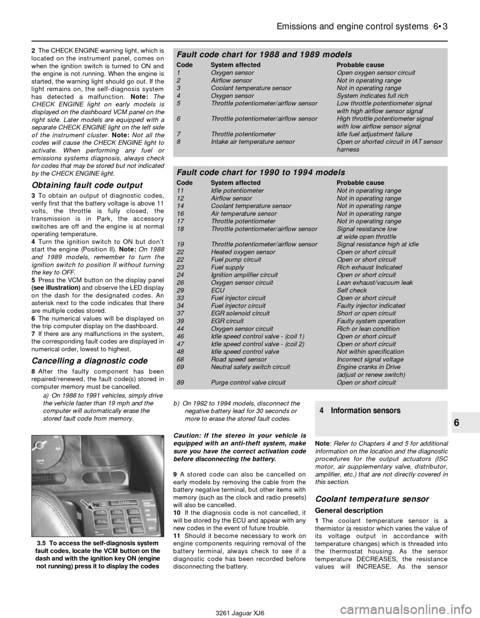
5Press the VCM button on the display panel
(see illustration)and observe the LED display
on the dash for the designated codes. An
asterisk next to the code indicates that there
are multiple codes stored.
6The numerical values will be displayed on
the trip computer display on the dashboard.
7If there are any malfunctions in the system,
the corresponding fault codes are displayed in
numerical order, lowest to highest.
Cancelling a diagnostic code
8After the faulty component has been
repaired/renewed, the fault code(s) stored in
computer memory must be cancelled.
a) On 1988 to 1991 vehicles, simply drive
the vehicle faster than 19 mph and the
computer will automatically erase the
stored fault code from memory.b) On 1992 to 1994 models, disconnect the
negative battery lead for 30 seconds or
more to erase the stored fault codes.
Caution: If the stereo in your vehicle is
equipped with an anti-theft system, make
sure you have the correct activation code
before disconnecting the battery.
9A stored code can also be cancelled on
early models by removing the cable from the
battery negative terminal, but other items with
memory (such as the clock and radio presets)
will also be cancelled.
10If the diagnosis code is not cancelled, it
will be stored by the ECU and appear with any
new codes in the event of future trouble.
11Should it become necessary to work on
engine components requiring removal of the
battery terminal, always check to see if a
diagnostic code has been recorded before
disconnecting the battery.
4 Information sensors
Note: Refer to Chapters 4 and 5 for additional
information on the location and the diagnostic
procedures for the output actuators (ISC
motor, air supplementary valve, distributor,
amplifier, etc.) that are not directly covered in
this section.
Coolant temperature sensor
General description
1The coolant temperature sensor is a
thermistor (a resistor which varies the value of
its voltage output in accordance with
temperature changes) which is threaded into
the thermostat housing. As the sensor
temperature DECREASES, the resistance
values will INCREASE. As the sensor
Emissions and engine control systems 6•3
6
3.5 To access the self-diagnosis system
fault codes, locate the VCM button on the
dash and with the ignition key ON (engine
not running) press it to display the codes
3261 Jaguar XJ6
Fault code chart for 1988 and 1989 models
Code System affected Probable cause
1 Oxygen sensor Open oxygen sensor circuit
2 Airflow sensor Not in operating range
3 Coolant temperature sensor Not in operating range
4 Oxygen sensor System indicates full rich
5 Throttle potentiometer/airflow sensor Low throttle potentiometer signal
with high airflow sensor signal
6 Throttle potentiometer/airflow sensor High throttle potentiometer signal
with low airflow sensor signal
7 Throttle potentiometer Idle fuel adjustment failure
8 Intake air temperature sensor Open or shorted circuit in IAT sensor
harness
Fault code chart for 1990 to 1994 models
Code System affected Probable cause
11 Idle potentiometer Not in operating range
12 Airflow sensor Not in operating range
14 Coolant temperature sensor Not in operating range
16 Air temperature sensor Not in operating range
17 Throttle potentiometer Not in operating range
18 Throttle potentiometer/airflow sensor Signal resistance low
at wide open throttle
19 Throttle potentiometer/airflow sensor Signal resistance high at idle
22 Heated oxygen sensor Open or short circuit
22 Fuel pump circuit Open or short circuit
23 Fuel supply Rich exhaust Indicated
24 Ignition amplifier circuit Open or short circuit
26 Oxygen sensor circuit Lean exhaust/vacuum leak
29 ECU Self check
33 Fuel injector circuit Open or short circuit
34 Fuel injector circuit Faulty injector indicated
37 EGR solenoid circuit Short or open circuit
39 EGR circuit Faulty system operation
44 Oxygen sensor circuit Rich or lean condition
46 Idle speed control valve - (coil 1) Open or short circuit
47 Idle speed control valve - (coil 2) Open or short circuit
48 Idle speed control valve Not within specification
68 Road speed sensor Incorrect signal voltage
69 Neutral safety switch circuit Engine cranks in Drive
(adjust or renew switch)
89 Purge control valve circuit Open or short circuit
Page 121 of 227
canister. If fuel is leaking, renew the canister
and check the hoses and hose routing.
9Inspect the canister. If it’s cracked or
damaged, renew it.
10Check for a clogged filter or a damaged
pressure relief valve. Using low pressure
compressed air (such as from a tyre pump),
blow into the canister tank pipe. Air should
flow freely from the other pipes. If a problem is
found, renew the canister.
11Check the operation of the thermal
vacuum valve (TVV). With the engine cold and
idling, check for ported vacuum to the
temperature vacuum switch. Vacuum should
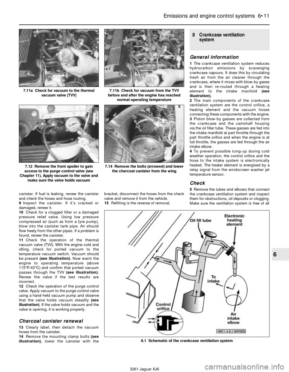
be present (see illustration). Now warm the
engine to operating temperature (above
115°F/43°C) and confirm that ported vacuum
passes through the TVV (see illustration).
Renew the valve if the test results are
incorrect.
12Check the operation of the purge control
valve. Apply vacuum to the purge control valve
using a hand-held vacuum pump and observe
that the valve holds vacuum steadily (see
illustration). If the valve holds vacuum and the
valve is opening, it is working properly.
Charcoal canister renewal
13Clearly label, then detach the vacuum
hoses from the canister.
14Remove the mounting clamp bolts (see
illustration), lower the canister with thebracket, disconnect the hoses from the check
valve and remove it from the vehicle.
15Refitting is the reverse of removal.
8 Crankcase ventilation
system
General information
1The crankcase ventilation system reduces
hydrocarbon emissions by scavenging
crankcase vapours. It does this by circulating
fresh air from the air cleaner through the
crankcase, where it mixes with blow-by gases
and is then re-routed through a heating
element to the intake manifold(see
illustration).
2The main components of the crankcase
ventilation system are the control orifice, a
heating element and the vacuum hoses
connecting these components with the engine.
3Piston blow-by gasses are collected from
the crankcase and the camshaft housing
via the oil filler tube. These gasses are fed into
the intake manifold at part throttle through the
part throttle orifice and when the engine is at
full throttle, the gasses are fed through the air
intake elbow.
4To prevent possible icing-up during cold
weather operation, the control orifice and the
hose to the intake system is electronically
heated. The heater element is energised by a
relay signal from the windscreen washer jet
temperature sensor.
Check
5Remove the tubes and elbows that connect
the crankcase ventilation system and inspect
them for obstructions, oil deposits or clogging.
Make sure the ventilation system is free of all
Emissions and engine control systems 6•11
6
7.11a Check for vacuum to the thermal
vacuum valve (TVV)7.11b Check for vacuum from the TVV
before and after the engine has reached
normal operating temperature
7.12 Remove the front spoiler to gain
access to the purge control valve (see
Chapter 11). Apply vacuum to the valve and
make sure the valve holds vacuum7.14 Remove the bolts (arrowed) and lower
the charcoal canister from the wing
8.1 Schematic of the crankcase ventilation system
3261 Jaguar XJ6
Page 122 of 227
obstructions to ensure complete recirculation
of gasses from the crankcase back into the
intake manifold. In the event of clogging, the
pressure will increase causing blow-by and oil
leaks through seals and gaskets.
6Check the operation of the heating element.
Check for battery voltage to the element while
the engine is cold. If no voltage is available
to the heating element, check the circuit from
the windscreen washer jet temperature
sensor.
Renewal
7Disconnect the electrical connector from
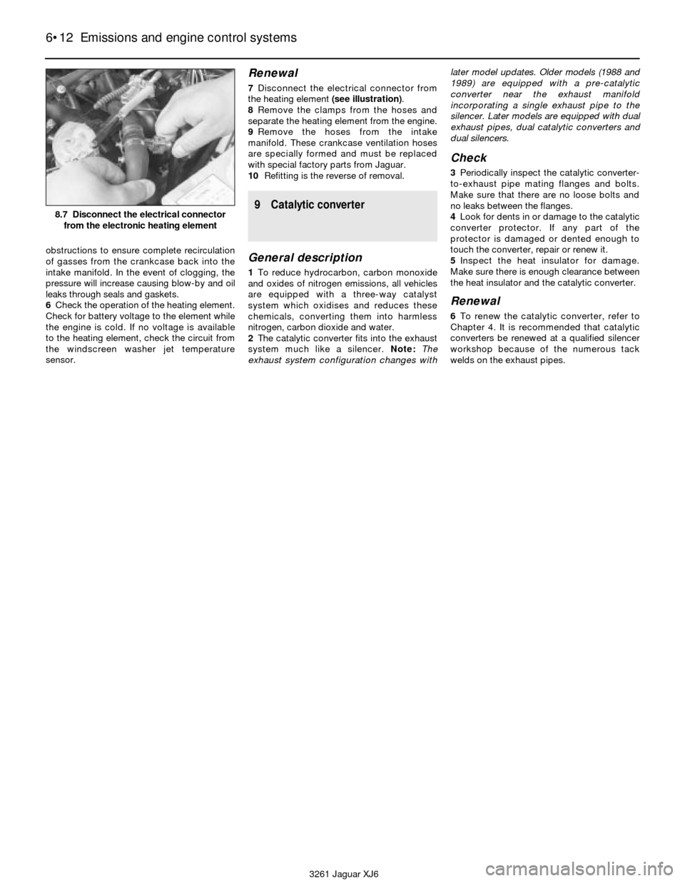
the heating element (see illustration).
8Remove the clamps from the hoses and
separate the heating element from the engine.
9Remove the hoses from the intake
manifold. These crankcase ventilation hoses
are specially formed and must be replaced
with special factory parts from Jaguar.
10Refitting is the reverse of removal.
9 Catalytic converter
General description
1To reduce hydrocarbon, carbon monoxide
and oxides of nitrogen emissions, all vehicles
are equipped with a three-way catalyst
system which oxidises and reduces these
chemicals, converting them into harmless
nitrogen, carbon dioxide and water.
2The catalytic converter fits into the exhaust
system much like a silencer. Note:The
exhaust system configuration changes withlater model updates. Older models (1988 and
1989) are equipped with a pre-catalytic
converter near the exhaust manifold
incorporating a single exhaust pipe to the
silencer. Later models are equipped with dual
exhaust pipes, dual catalytic converters and
dual silencers.
Check
3Periodically inspect the catalytic converter-
to-exhaust pipe mating flanges and bolts.
Make sure that there are no loose bolts and
no leaks between the flanges.
4Look for dents in or damage to the catalytic
converter protector. If any part of the
protector is damaged or dented enough to
touch the converter, repair or renew it.
5Inspect the heat insulator for damage.
Make sure there is enough clearance between
the heat insulator and the catalytic converter.
Renewal
6To renew the catalytic converter, refer to
Chapter 4. It is recommended that catalytic
converters be renewed at a qualified silencer
workshop because of the numerous tack
welds on the exhaust pipes.
6•12 Emissions and engine control systems
3261 Jaguar XJ6
8.7 Disconnect the electrical connector
from the electronic heating element
Page 163 of 227
3261 Jaguar XJ6
12
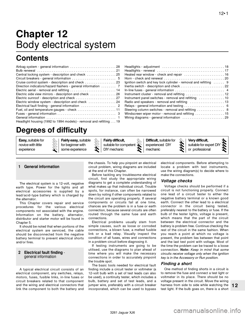
Chapter 12
Body electrical system
1 General information
The electrical system is a 12-volt, negative
earth type. Power for the lights and all
electrical accessories is supplied by a
lead/acid-type battery which is charged by
the alternator.
This Chapter covers repair and service
procedures for the various electrical
components not associated with the engine.
Information on the battery, alternator,
distributor and starter motor will be found in
Chapter 5.
It should be noted that when portions of the
electrical system are serviced, the cable
should be disconnected from the negative
battery terminal to prevent electrical shorts
and/or fires.
2 Electrical fault finding-
general information
A typical electrical circuit consists of an
electrical component, any switches, relays,
motors, fuses, fusible links, in-line fuses or
circuit breakers related to that component
and the wiring and electrical connectors that
link the component to both the battery andthe chassis. To help you pinpoint an electrical
circuit problem, wiring diagrams are included
at the end of this Chapter.
Before tackling any troublesome electrical
circuit, first study the appropriate wiring
diagrams to get a complete understanding of
what makes up that individual circuit. Trouble
spots, for instance, can often be narrowed
down by noting if other components related to
the circuit are operating properly. If several
components or circuits fail at one time,
chances are the problem is in a fuse or earth
connection, because several circuits are often
routed through the same fuse and earth
connections.
Electrical problems usually stem from
simple causes, such as loose or corroded
connections, a blown fuse, a melted fusible
link or a bad relay. Visually inspect the
condition of all fuses, wires and connections
in a problem circuit before diagnosing it.
If testing instruments are going to be
utilised, use the diagrams to plan ahead of
time where you will make the necessary
connections in order to accurately pinpoint
the trouble spot.
The basic tools needed for electrical fault
finding include a circuit tester or voltmeter (a
12-volt bulb with a set of test leads can also
be used), a continuity tester, which includes a
bulb, battery and set of test leads, and a
jumper wire, preferably with a circuit breaker
incorporated, which can be used to bypasselectrical components. Before attempting to
locate a problem with test instruments,
use the wiring diagram(s) to decide where to
make the connections.
Voltage checks
Voltage checks should be performed if a
circuit is not functioning properly. Connect
one lead of a circuit tester to either the
negative battery terminal or a known good
earth. Connect the other lead to a electrical
connector in the circuit being tested,
preferably nearest to the battery or fuse. If the
bulb of the tester lights, voltage is present,
which means that the part of the circuit
between the electrical connector and the
battery is problem free. Continue checking the
rest of the circuit in the same fashion. When
you reach a point at which no voltage is
present, the problem lies between that point
and the last test point with voltage. Most of
the time the problem can be traced to a loose
connection. Note:Keep in mind that some
circuits receive voltage only when the ignition
key is in the Accessory or Run position.
Finding a short
One method of finding shorts in a circuit is
to remove the fuse and connect a test light or
voltmeter in its place. There should be no
voltage present in the circuit. Move the wiring
harness from side to side while watching the
test light. If the bulb goes on, there is a short Airbag system - general information . . . . . . . . . . . . . . . . . . . . . . . . . 28
Bulb renewal . . . . . . . . . . . . . . . . . . . . . . . . . . . . . . . . . . . . . . . . . . . 21
Central locking system - description and check . . . . . . . . . . . . . . . . 25
Circuit breakers - general information . . . . . . . . . . . . . . . . . . . . . . . . 5
Cruise control system - description and check . . . . . . . . . . . . . . . . . 23
Direction indicators/hazard flashers - general information . . . . . . . . 7
Electric aerial - removal and refitting . . . . . . . . . . . . . . . . . . . . . . . . . 14
Electric side view mirrors - description and check . . . . . . . . . . . . . . 26
Electric sunroof - description and check . . . . . . . . . . . . . . . . . . . . . . 27
Electric window system - description and check . . . . . . . . . . . . . . . 24
Electrical fault finding - general information . . . . . . . . . . . . . . . . . . . 2
Fuel, oil and temperature gauges - check . . . . . . . . . . . . . . . . . . . . . 11
Fuses - general information . . . . . . . . . . . . . . . . . . . . . . . . . . . . . . . . 3
General information . . . . . . . . . . . . . . . . . . . . . . . . . . . . . . . . . . . . . . 1
Headlight housing (1992 to 1994 models) - removal and refitting . . . 19Headlights - adjustment . . . . . . . . . . . . . . . . . . . . . . . . . . . . . . . . . . 18
Headlights - renewal . . . . . . . . . . . . . . . . . . . . . . . . . . . . . . . . . . . . . 17
Heated rear window - check and repair . . . . . . . . . . . . . . . . . . . . . . 16
Horn - check and renewal . . . . . . . . . . . . . . . . . . . . . . . . . . . . . . . . . 20
Ignition switch and key lock cylinder - removal and refitting . . . . . . 9
Inertia switch - description and check . . . . . . . . . . . . . . . . . . . . . . . . 22
In-line fuses - general information . . . . . . . . . . . . . . . . . . . . . . . . . . . 4
Instrument cluster - removal and refitting . . . . . . . . . . . . . . . . . . . . . 12
Instrument panel switches - removal and refitting . . . . . . . . . . . . . . 10
Radio and speakers - removal and refitting . . . . . . . . . . . . . . . . . . . 13
Relays - general information and testing . . . . . . . . . . . . . . . . . . . . . . 6
Steering column switches - removal and refitting . . . . . . . . . . . . . . . 8
Windscreen wiper motor - removal and refitting . . . . . . . . . . . . . . . . 15
Wiring diagrams - general information . . . . . . . . . . . . . . . . . . . . . . . 29
12•1
Contents
Easy,suitable for
novice with little
experienceFairly easy,suitable
for beginner with
some experienceFairly difficult,
suitable for competent
DIY mechanic
Difficult,suitable for
experienced DIY
mechanicVery difficult,
suitable for expert DIY
or professional
Degrees of difficulty
54321