wheel JAGUAR XJ6 1997 2.G Owner's Manual
[x] Cancel search | Manufacturer: JAGUAR, Model Year: 1997, Model line: XJ6, Model: JAGUAR XJ6 1997 2.GPages: 227, PDF Size: 7.2 MB
Page 54 of 227

2Use a centre punch or paint to make
alignment marks on the driveplate and
crankshaft to ensure correct alignment during
refitting(see illustration).
3Remove the bolts that secure the driveplate
to the crankshaft. If the crankshaft turns,
wedge a screwdriver through a hole in the
driveplate to keep it from turning (see
illustration).
4Remove the driveplate from the crankshaft.
A spacer is located behind the driveplate(see
illustration). Pry it off and store it with the
driveplate.
Warning: The ring-gear teeth
may be sharp, wear gloves to
protect your hands when
handling the driveplate.
Refitting
5Clean the driveplate to remove grease and
oil. Inspect the surface for cracks. Check for
cracked and broken ring gear teeth. Note:If
there is any damage to the driveplate, replace
the driveplate with a new driveplate, a new
spacer and new bolts. Improved parts are
available as a set from the dealer.
6Clean and inspect the mating surfaces of
the driveplate and the crankshaft. If the
crankshaft rear seal is leaking, renew it before
refitting the driveplate (see Section 15).
7Position the driveplate against the
crankshaft. Be sure to align the marks made
during removal. Some models may have an
alignment dowel or staggered bolt holes to
ensure correct refitting. Before refitting the
bolts, apply thread-locking compound to the
bolt threads.
8Wedge a screwdriver in the ring gear teeth
to keep the driveplate from turning and tighten
the bolts to the torque listed in this Chapter’s
Specifications. Follow a criss-cross pattern
and work up to the final torque in three or four
steps.
9The remainder of refitting is the reverse of
the removal procedure.
15 Crankshaft rear oil seal-
renewal
4
1The transmission adapter plate and
driveplate must be removed from the car for
this procedure (see Chapter 7).
2Remove the bolts, and detach the oil seal
retainer. Remove the gasket material from the
block and the seal retainer (see illustration).
3Position the oil seal and retainer assembly
between two wood blocks on a workbench
and drive the old seal out from the backside
(see illustration).
4The new seal must be driven into the
retainer plate from the engine side. Drive thenew seal into the retainer with a wood block
or a section of pipe slightly smaller in diameter
than the outside diameter of the seal (see
illustration). The seal should be driven in only
until it is flush with the transmission side of
the retainer.
Caution: The new seal comes with a
special plastic refitting sleeve inserted in
the seal. It is designed to allow the seal to
slide over the end of the crankshaft
without displacing the seal lip. Do NOT
remove this plastic sleeve until the retainer
and seal have been installed on the engine.
5Lubricate the seal area of the crankshaft
with engine oil. Apply a bead of RTV sealant
to the sealing surface of the retainer (see
illustration).
Engine in-car repair procedures 2A•17
2A
14.2 Mark the driveplate and the
crankshaft so they can be reassembled in
the same relative position14.3 Use a screwdriver to secure the
flywheel while the bolts are removed14.4 Pry off the driveplate spacer - if a
driveplate is replaced, the spacer should
be replaced also
15.2 Remove the bolts (arrowed) and the
crankshaft rear oil seal retainer from the
back of the engine block15.3 After removing the retainer assembly
from the engine block, support it between
two wood blocks and drive out the old seal
with a drift punch and hammer
15.4 Drive the new seal into the retainer
with a wood block
3261 Jaguar XJ6
15.5 Apply RTV sealant
to the sealing surface
Page 58 of 227
rebuilt engine or short block, some rebuilders
will not warranty their engines unless the
radiator has been professionally flushed. Also,
we don’t recommend overhauling the oil
pump - always refit a new one when an engine
is rebuilt.
Before beginning the engine overhaul, read
through the entire procedure to familiarise
yourself with the scope and requirements of
the job. Overhauling an engine isn’t difficult,
but it is time-consuming. Plan on the vehicle
being tied up for a minimum of two weeks,
especially if parts must be taken to an
automotive machine workshop for repair or
reconditioning. Check on availability of parts
and make sure that any necessary special
tools and equipment are obtained in advance.
Most work can be done with typical hand
tools, although a number of precision
measuring tools are required for inspecting
parts to determine if they must be renewed.
Often an automotive machine workshop will
handle the inspection of parts and offer
advice concerning reconditioning and
renewal. Note:Always wait until the engine
has been completely dismantled and all
components, especially the engine block,
have been inspected before deciding what
service and repair operations must be
performed by an automotive machine
workshop. Since the engine block’s condition
will be the major factor to consider when
determining whether to overhaul the original
engine or buy a rebuilt one, never purchase
parts or have machine work done on other
components until the engine block has been
thoroughly inspected. As a general rule, time
is the primary cost of an overhaul, so it
doesn’t pay to refit worn or substandard
parts.
If it turns out that a number of major
components are beyond reconditioning, it
may be cost effective to buy a factory-rebuilt
engine from a Jaguar dealership.
As a final note, to ensure maximum life and
minimum trouble from a rebuilt engine,
everything must be assembled with care in a
spotlessly-clean environment.
3 Vacuum gauge
diagnostic checks
2
A vacuum gauge provides valuable
information about what is going on in the
engine at a low cost. You can check for worn
rings or cylinder walls, leaking cylinder head or
intake manifold gaskets, incorrect carburettor
adjustments, restricted exhaust, stuck or
burned valves, weak valve springs, improper
ignition or valve timing and ignition problems.
Unfortunately, vacuum gauge readings are
easy to misinterpret, so they should be used
with other tests to confirm the diagnosis.
Both the absolute readings and the rate of
needle movement are important for accurate
interpretation. Most gauges measure vacuumin inches of mercury (in-Hg). As vacuum
increases (or atmospheric pressure decreases),
the reading will decrease. Also, for every
1000 foot increase in elevation above sea level;
the gauge readings will decrease about one
inch of mercury.
Connect the vacuum gauge directly to
intake manifold vacuum, not to ported (above
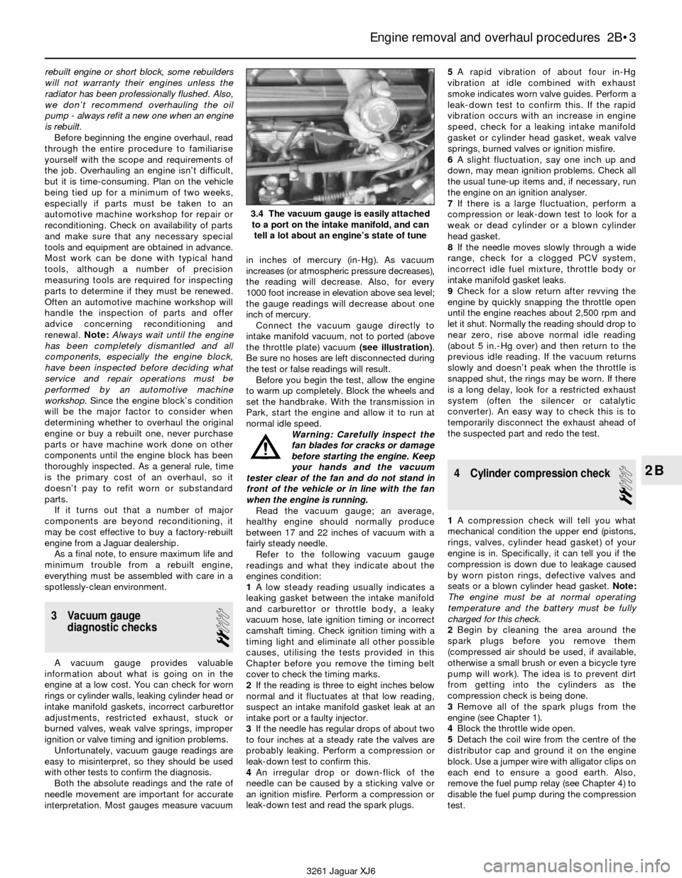
the throttle plate) vacuum (see illustration).
Be sure no hoses are left disconnected during
the test or false readings will result.
Before you begin the test, allow the engine
to warm up completely. Block the wheels and
set the handbrake. With the transmission in
Park, start the engine and allow it to run at
normal idle speed.
Warning: Carefully inspect the
fan blades for cracks or damage
before starting the engine. Keep
your hands and the vacuum
tester clear of the fan and do not stand in
front of the vehicle or in line with the fan
when the engine is running.
Read the vacuum gauge; an average,
healthy engine should normally produce
between 17 and 22 inches of vacuum with a
fairly steady needle.
Refer to the following vacuum gauge
readings and what they indicate about the
engines condition:
1A low steady reading usually indicates a
leaking gasket between the intake manifold
and carburettor or throttle body, a leaky
vacuum hose, late ignition timing or incorrect
camshaft timing. Check ignition timing with a
timing light and eliminate all other possible
causes, utilising the tests provided in this
Chapter before you remove the timing belt
cover to check the timing marks.
2If the reading is three to eight inches below
normal and it fluctuates at that low reading,
suspect an intake manifold gasket leak at an
intake port or a faulty injector.
3If the needle has regular drops of about two
to four inches at a steady rate the valves are
probably leaking. Perform a compression or
leak-down test to confirm this.
4An irregular drop or down-flick of the
needle can be caused by a sticking valve or
an ignition misfire. Perform a compression or
leak-down test and read the spark plugs.5A rapid vibration of about four in-Hg
vibration at idle combined with exhaust
smoke indicates worn valve guides. Perform a
leak-down test to confirm this. If the rapid
vibration occurs with an increase in engine
speed, check for a leaking intake manifold
gasket or cylinder head gasket, weak valve
springs, burned valves or ignition misfire.
6A slight fluctuation, say one inch up and
down, may mean ignition problems. Check all
the usual tune-up items and, if necessary, run
the engine on an ignition analyser.
7If there is a large fluctuation, perform a
compression or leak-down test to look for a
weak or dead cylinder or a blown cylinder
head gasket.
8If the needle moves slowly through a wide
range, check for a clogged PCV system,
incorrect idle fuel mixture, throttle body or
intake manifold gasket leaks.
9Check for a slow return after revving the
engine by quickly snapping the throttle open
until the engine reaches about 2,500 rpm and
let it shut. Normally the reading should drop to
near zero, rise above normal idle reading
(about 5 in.-Hg over) and then return to the
previous idle reading. If the vacuum returns
slowly and doesn’t peak when the throttle is
snapped shut, the rings may be worn. If there
is a long delay, look for a restricted exhaust
system (often the silencer or catalytic
converter). An easy way to check this is to
temporarily disconnect the exhaust ahead of
the suspected part and redo the test.
4 Cylinder compression check
2
1A compression check will tell you what
mechanical condition the upper end (pistons,
rings, valves, cylinder head gasket) of your
engine is in. Specifically, it can tell you if the
compression is down due to leakage caused
by worn piston rings, defective valves and
seats or a blown cylinder head gasket. Note:
The engine must be at normal operating
temperature and the battery must be fully
charged for this check.
2Begin by cleaning the area around the
spark plugs before you remove them
(compressed air should be used, if available,
otherwise a small brush or even a bicycle tyre
pump will work). The idea is to prevent dirt
from getting into the cylinders as the
compression check is being done.
3Remove all of the spark plugs from the
engine (see Chapter 1).
4Block the throttle wide open.
5Detach the coil wire from the centre of the
distributor cap and ground it on the engine
block. Use a jumper wire with alligator clips on
each end to ensure a good earth. Also,
remove the fuel pump relay (see Chapter 4) to
disable the fuel pump during the compression
test.
Engine removal and overhaul procedures 2B•3
2B
3.4 The vacuum gauge is easily attached
to a port on the intake manifold, and can
tell a lot about an engine’s state of tune
3261 Jaguar XJ6
Page 60 of 227
11Disconnect the throttle linkage,
transmission linkage (and dipstick tube) and
speed control cable, if equipped, from the
engine (see Chapters 4 and 7).
12Refer to Part A of this Chapter and
remove the intake and exhaust manifolds.
13Unbolt the power steering pump (see
Chapter 10). Tie the pump aside without
disconnecting the hoses. Refer to Part A for
removal of the hydraulic pump (if equipped)
from the timing chain cover.
14On air-conditioned models, unbolt the
compressor and set it aside. Do not
disconnect the refrigerant hoses. Note:Wire
the compressor out of the way with a coat
hanger, don’t let the compressor hang on the
hoses.
15Refer to Part A of this Chapter and
remove the drivebelts, water pump pulley and
crankshaft pulley.
16Attach a lifting sling to the engine.
Position a hoist and connect the sling to it.
Take up the slack until there is slight tension
on the hoist.
17With a trolley jack and piece of wood
supporting the bottom of the transmission
sump, refer to Chapter 8 and remove the
driveshaft and rear transmission mount.
Warning: Do not place any part
of your body under the
engine/transmission when it’s
supported only by a hoist or
other lifting device.
18With the hoist taking the weight of the
engine, unbolt the engine mounts (see Part A
of this Chapter).
19Recheck to be sure nothing is still
connecting the engine or transmission to the
vehicle. Disconnect and label anything still
remaining.
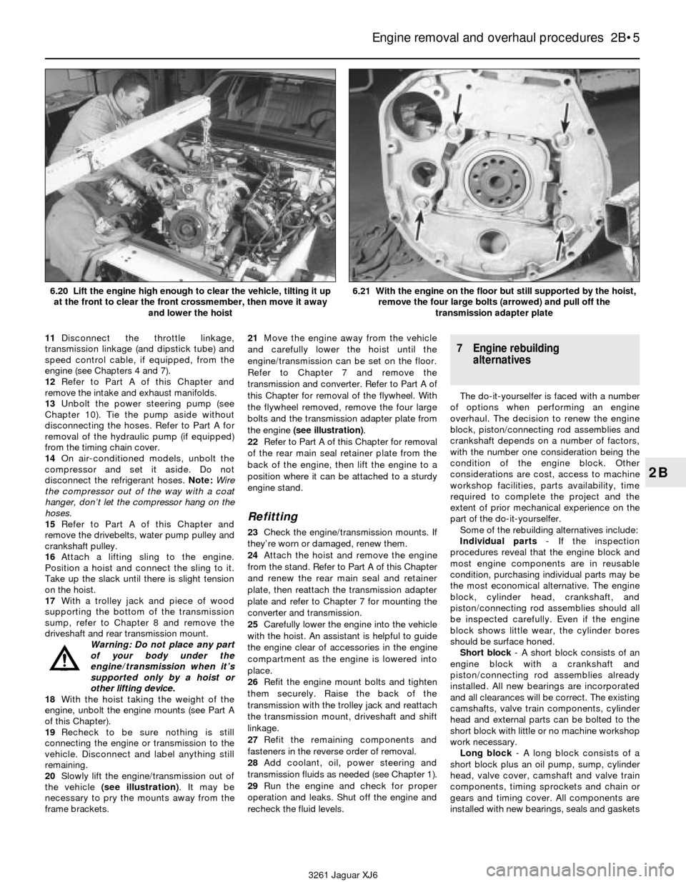
20Slowly lift the engine/transmission out of
the vehicle (see illustration). It may be
necessary to pry the mounts away from the
frame brackets.21Move the engine away from the vehicle
and carefully lower the hoist until the
engine/transmission can be set on the floor.
Refer to Chapter 7 and remove the
transmission and converter. Refer to Part A of
this Chapter for removal of the flywheel. With
the flywheel removed, remove the four large
bolts and the transmission adapter plate from
the engine (see illustration).
22Refer to Part A of this Chapter for removal
of the rear main seal retainer plate from the
back of the engine, then lift the engine to a
position where it can be attached to a sturdy
engine stand.
Refitting
23Check the engine/transmission mounts. If
they’re worn or damaged, renew them.
24Attach the hoist and remove the engine
from the stand. Refer to Part A of this Chapter
and renew the rear main seal and retainer
plate, then reattach the transmission adapter
plate and refer to Chapter 7 for mounting the
converter and transmission.
25Carefully lower the engine into the vehicle
with the hoist. An assistant is helpful to guide
the engine clear of accessories in the engine
compartment as the engine is lowered into
place.
26Refit the engine mount bolts and tighten
them securely. Raise the back of the
transmission with the trolley jack and reattach
the transmission mount, driveshaft and shift
linkage.
27Refit the remaining components and
fasteners in the reverse order of removal.
28Add coolant, oil, power steering and
transmission fluids as needed (see Chapter 1).
29Run the engine and check for proper
operation and leaks. Shut off the engine and
recheck the fluid levels.
7 Engine rebuilding
alternatives
The do-it-yourselfer is faced with a number
of options when performing an engine
overhaul. The decision to renew the engine
block, piston/connecting rod assemblies and
crankshaft depends on a number of factors,
with the number one consideration being the
condition of the engine block. Other
considerations are cost, access to machine
workshop facilities, parts availability, time
required to complete the project and the
extent of prior mechanical experience on the
part of the do-it-yourselfer.
Some of the rebuilding alternatives include:
Individual parts- If the inspection
procedures reveal that the engine block and
most engine components are in reusable
condition, purchasing individual parts may be
the most economical alternative. The engine
block, cylinder head, crankshaft, and
piston/connecting rod assemblies should all
be inspected carefully. Even if the engine
block shows little wear, the cylinder bores
should be surface honed.
Short block- A short block consists of an
engine block with a crankshaft and
piston/connecting rod assemblies already
installed. All new bearings are incorporated
and all clearances will be correct. The existing
camshafts, valve train components, cylinder
head and external parts can be bolted to the
short block with little or no machine workshop
work necessary.
Long block- A long block consists of a
short block plus an oil pump, sump, cylinder
head, valve cover, camshaft and valve train
components, timing sprockets and chain or
gears and timing cover. All components are
installed with new bearings, seals and gaskets
Engine removal and overhaul procedures 2B•5
2B
3261 Jaguar XJ6 6.20 Lift the engine high enough to clear the vehicle, tilting it up
at the front to clear the front crossmember, then move it away
and lower the hoist
6.21 With the engine on the floor but still supported by the hoist,
remove the four large bolts (arrowed) and pull off the
transmission adapter plate
Page 70 of 227

21 Engine overhaul-
reassembly sequence
1Before beginning engine reassembly, make
sure you have all the necessary new parts,
gaskets and seals as well as the following
items on hand:
Common hand tools
A 1/2-inch drive torque wrench
Piston ring refitting tool
Piston ring compressor
Short lengths of rubber or plastic hose to
fit over connecting rod bolts
Plastigauge
Feeler gauges
A fine-tooth file
New engine oil
Engine assembly lube or moly-base
grease
Gasket sealer
Thread locking compound
Special Jaguar tools:
Engine lifting brackets (18G 1465)
Timing damper simulator (18E 1436)
Camshaft TDC tool (18G 1433)
2In order to save time and avoid problems,
engine reassembly must be done in the
following general order:
Piston rings (Part B)
Crankshaft and main bearings (Part B)
Piston/connecting rod assemblies (Part B)
Rear main (crankshaft) oil seal (Part B)
Auxiliary shaft (Part A)
Timing chains and sprockets (Part A)
Oil pump (Part A)
Timing chain cover (Part A)
Cylinder head and lifters (Part A)
Camshafts (Part A)
Oil pick-up (Part A)
Sump (Part A)
Intake and exhaust manifolds (Part A)
Valve cover (Part A)
Flywheel/driveplate (Part A)
22 Piston rings- refitting
3
1Before refitting the new piston rings, the ring
end gaps must be checked. It’s assumed that
the piston ring groove clearance has been
checked and verified correct (see Section 18).
2Lay out the piston/connecting rod
assemblies and the new ring sets so the ring
sets will be matched with the same piston and
cylinder during the end gap measurement and
engine assembly.
3Insert the top (number one) ring into the first
cylinder and square it up with the cylinder
walls by pushing it in with the top of the piston
(see illustration). The ring should be near the
bottom of the cylinder, at the lower limit of
ring travel.
4To measure the end gap, slip feeler gauges
between the ends of the ring until a gauge
equal to the gap width is found (see
illustration). The feeler gauge should slide
between the ring ends with a slight amount of
drag. Compare the measurement to that
found in this Chapter’s Specifications. If the
gap is larger or smaller than specified,
double-check to make sure you have the
correct rings before proceeding.
5If the gap is too small, it must be enlarged
or the ring ends may come in contact with
each other during engine operation, which
can cause serious damage to the engine. The
end gap can be increased by filing the ring
ends very carefully with a fine file. Mount thefile in a vice equipped with soft jaws, slip the
ring over the file with the ends contacting the
file face and slowly move the ring to remove
material from the ends(see illustration).
Caution: When performing this operation,
file only from the outside in, and after the
correct gap is achieved, deburr the filed
ends of the rings with a fine whetstone.
6Excess end gap isn’t critical unless it’s
greater than Specifications. Again, double-
check to make sure you have the correct rings
for your engine.
7Repeat the procedure for each ring that will
be installed in the first cylinder and for each
ring in the remaining cylinders. Remember to
keep rings, pistons and cylinders matched.
8Once the ring end gaps have been
checked/corrected, the rings can be installed
on the pistons.
9The oil control ring (lowest one on the
piston) is usually installed first. It’s composed
of three separate components. Slip the
spacer/expander into the groove (see
illustration). If an anti-rotation tang is used,
make sure it’s inserted into the drilled hole in
the ring groove. Next, refit the lower side rail.
Don’t use a piston ring refitting tool on the oil
ring side rails, as they may be damaged.
Instead, place one end of the side rail into the
groove between the spacer/expander and the
ring land, hold it firmly in place and slide a
finger around the piston while pushing the rail
into the groove (see illustrations). Next, refit
the upper side rail in the same manner.
10After the three oil ring components have
been installed, check to make sure that both
Engine removal and overhaul procedures 2B•15
2B
22.3 When checking piston ring end gap,
the ring must be square in the cylinder
bore (this is done by pushing the ring down
with the top of a piston as shown)22.4 With the ring square in the cylinder,
measure the end gap with a feeler gauge22.5 If the end gap is too small, clamp a
file in a vice and file the ring ends (from the
outside in only) to enlarge the gap slightly
22.9a Refit the spacer/expander in the oil
control ring groove22.9b DO NOT use a piston ring refitting
tool when refitting the oil ring side rails
3261 Jaguar XJ6
Page 80 of 227
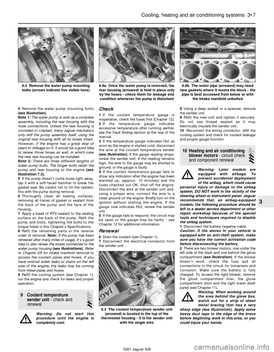
4Remove the water pump mounting bolts
(see illustration).
Note 1:The water pump is sold as a complete
assembly, including the rear housing with the
hose connections. Unless the rear housing is
corroded or cracked, many Jaguar mechanics
only refit the pump assembly itself, using the
original rear housing with all its hoses intact.
However, if the engine has a great deal of
years or mileage on it, it would be a good idea
to renew those hoses as well, in which case
the new rear housing can be installed.
Note 2:There are three different lengths of
water pump bolts. The longer bolts retain the
pump and rear housing to the engine(see
illustration 7.3).
5If the pump doesn’t come loose right away,
tap it with a soft-faced hammer to break the
gasket seal. Be careful not to hit the radiator
fins with the pump during removal.
6Thoroughly clean all sealing surfaces,
removing all traces of gasket or sealant from
the back of the pump and the face of the
housing.
7Apply a bead of RTV sealant to the sealing
surface on the back of the pump. Refit the
pump and bolts, tightening the bolts to the
torque listed in this Chapter’s Specifications.
8Refit the remaining parts in the reverse
order of removal. Note:If the pump has been
renewed after many miles of usage, it’s a good
idea to also renew the hoses connected to the
water pump housing(see illustrations). Refer
to Chapter 2A for intake manifold removal to
access the coolant pipes and hoses. If you
have noticed water leaks or stains on the left
side of the engine, the leaks may be coming
from these pipes and hoses.
9Refill the cooling system (see Chapter 1),
run the engine and check for leaks and proper
operation.
9 Coolant temperature
sender unit- check and
renewal
2
Warning: Do not start this
procedure until the engine is
completely cool.
Check
1If the coolant temperature gauge is
inoperative, check the fuses first (Chapter 12).
2If the temperature gauge indicates
excessive temperature after running awhile,
see the Fault finding section at the rear of the
manual.
3If the temperature gauge indicates Hot as
soon as the engine is started cold, disconnect
the wire at the coolant temperature sender
(see illustration). If the gauge reading drops,
renew the sender unit. If the reading remains
high, the wire to the gauge may be shorted to
ground, or the gauge is faulty.
4If the coolant temperature gauge fails to
show any indication after the engine has been
warmed up, (approx. 10 minutes) and the
fuses checked out OK, shut off the engine.
Disconnect the wire at the sender unit and,
using a jumper wire, connect the wire to a
clean ground on the engine. Briefly turn on the
ignition without starting the engine. If the
gauge now indicates Hot, renew the sender
unit.
5If the gauge fails to respond, the circuit may
be open or the gauge may be faulty - see
Chapter 12 for additional information.
Renewal
6Drain the coolant (see Chapter 1).
7Disconnect the electrical connector from
the sender unit.8Using a deep socket or a spanner, remove
the sender unit.
9Refit the new unit and tighten it securely.
Do not use thread sealant as it may
electrically insulate the sender unit.
10Reconnect the wiring connector, refill the
cooling system and check for coolant leakage
and proper gauge function.
10 Heating and air conditioning
blower motors- circuit check
and component renewal
3
Warning: Later models are
equipped with airbags. To
prevent accidental deployment
of the airbag, which could cause
personal injury or damage to the airbag
system, DO NOT work in the vicinity of the
steering wheel or instrument panel. Jaguar
recommends that, on airbag-equipped
models, the following procedure should be
left to a dealer service department or other
repair workshop because of the special
tools and techniques required to disable
the airbag system.
1Disconnect the battery negative cable.
Caution: If the stereo in your vehicle is
equipped with an anti-theft system, make
sure you have the correct activation code
before disconnecting the battery.
2There are two blower motors, one under the
left side of the dash and one behind the glove
compartment (see illustration). If the blower
doesn’t work, check the fuse and all
connections in the circuit for looseness and
corrosion. Make sure the battery is fully
charged. To access the right blower, remove
the glove compartment liner, the glove
compartment door and the right lower dash
panel (see Chapter 11).
Warning: When working around
the area behind the glove box,
watch out for a strip of sheet
metal bracing that has a very
sharp edge (see illustration). Apply some
heavy duct tape to the edge of the brace
before beginning work in this area, or you
could injure your hands.
Cooling, heating and air conditioning systems 3•7
3
8.4 Remove the water pump mounting
bolts (arrows indicate five visible here)8.8a Once the water pump is removed, the
rear housing (arrowed) is held in place only
by the hoses - check them for leakage and
condition whenever the pump is disturbed8.8b The water pipe (arrowed) may need
new gaskets where it meets the block - the
pipe is best accessed from below or with
the intake manifold unbolted
9.3 The coolant temperature sender unit
(arrowed) is located in the top of the
thermostat housing - it is the sender unit
with the single wire
3261 Jaguar XJ6
Page 82 of 227

11Separate the housing halves and pull up
the plastic plate holding the motor and fan
(see illustration). The fan doesn’t come off
the motor, but loosen the clamp-bolt on the
motor’s mount bracket and slide the motor
and fan out for renewal (see illustration).
Note:Some 1988 models had problems with
cracking of the fan blades and noise from the
blowers. These blowers and fans have been
superseded with improved parts, available
from your Jaguar dealer.
12When either blower housing is separated,
you’ll find two relays mounted inside (see
illustration). These are the blower isolation
relay and blower relay. Before refitting the
blower housing in the car, refer to Chapter 12
for testing of these relays.
13Refitting is the reverse of removal. Check
for proper operation.11 Heater core-
removal and refitting
4
Warning: Later model vehicles
are equipped with airbags. To
prevent the accidental deploy-
ment of the airbag, which could
cause personal injury or damage to the
airbag system, DO NOT work in the vicinity
of the steering wheel or instrument panel.
The manufacturer recommends that, on
airbag-equipped models, the following
procedure should be left to a dealer service
department or other repair workshop
because of the special tools and techniques
required to disable the airbag system.1Disconnect the battery negative cable.
Caution: If the stereo in your vehicle is
equipped with an anti-theft system, make
sure you have the correct activation code
before disconnecting the battery.
2Drain the cooling system (see Chapter 1).
Disconnect the heater hoses where they enter
the bulkhead (see illustration). Note:Use
compressed air in one of the pipes to blow out
any remaining coolant and collect it. This will
prevent any spills on the carpeting when the
heater core is removed. Plug the pipes to
prevent any remaining coolant from spilling out.
3Refer to Chapter 11 for removal of the
under-dash panels on both the driver and
passenger sides, and removal of the glovebox.
Warning: When working around
the area behind the glove box,
watch out for a strip of sheet
Cooling, heating and air conditioning systems 3•9
3
3261 Jaguar XJ6 10.11a Separate the housing halves - the blower motor (arrowed)
is attached to a plastic plate sandwiched between the
two housing halves
10.11b Loosen the clamp bolt (arrowed) on the motor bracket and
then pull the motor and fan out as an assembly
10.12 Inside the blower case are the blower and isolation relays
(arrowed) - while the case is apart, test these relays for
proper operation11.2 Disconnect the heater hoses from the pipes at the bulkhead
(small arrows) - the large arrow indicates the evaporator case
retaining nut
Page 83 of 227
metal bracing that has a very sharp edge
(see illustration 10.2b). Apply some heavy
duct tape to the edge of the brace before
beginning work in this area, or you could
injure your hands.
4On the passenger’s side, under the dash,
remove the screws holding the plastic cover
where the heater pipes enter the heater/air
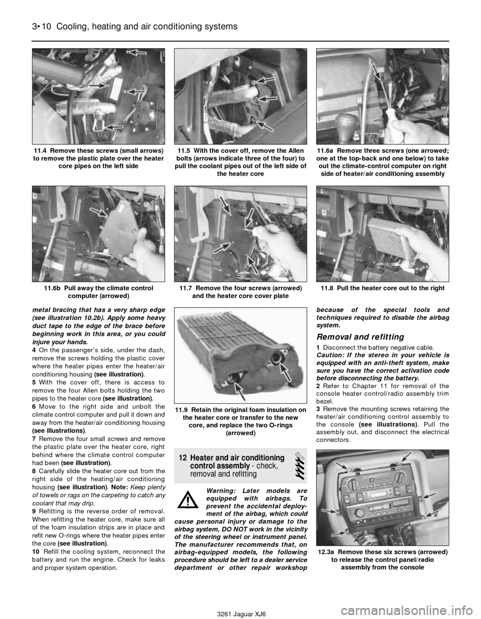
conditioning housing (see illustration).
5With the cover off, there is access to
remove the four Allen bolts holding the two
pipes to the heater core (see illustration).
6Move to the right side and unbolt the
climate control computer and pull it down and
away from the heater/air conditioning housing
(see illustrations).
7Remove the four small screws and remove
the plastic plate over the heater core, right
behind where the climate control computer
had been (see illustration).
8Carefully slide the heater core out from the
right side of the heating/air conditioning
housing (see illustration). Note:Keep plenty
of towels or rags on the carpeting to catch any
coolant that may drip.
9Refitting is the reverse order of removal.
When refitting the heater core, make sure all
of the foam insulation strips are in place and
refit new O-rings where the heater pipes enter
the core (see illustration).
10Refill the cooling system, reconnect the
battery and run the engine. Check for leaks
and proper system operation.
12 Heater and air conditioning
control assembly- check,
removal and refitting
4
Warning: Later models are
equipped with airbags. To
prevent the accidental deploy-
ment of the airbag, which could
cause personal injury or damage to the
airbag system, DO NOT work in the vicinity
of the steering wheel or instrument panel.
The manufacturer recommends that, on
airbag-equipped models, the following
procedure should be left to a dealer service
department or other repair workshopbecause of the special tools and
techniques required to disable the airbag
system.
Removal and refitting
1Disconnect the battery negative cable.
Caution: If the stereo in your vehicle is
equipped with an anti-theft system, make
sure you have the correct activation code
before disconnecting the battery.
2Refer to Chapter 11 for removal of the
console heater control/radio assembly trim
bezel.
3Remove the mounting screws retaining the
heater/air conditioning control assembly to
the console (see illustrations). Pull the
assembly out, and disconnect the electrical
connectors.
3•10 Cooling, heating and air conditioning systems
11.4 Remove these screws (small arrows)
to remove the plastic plate over the heater
core pipes on the left side11.5 With the cover off, remove the Allen
bolts (arrows indicate three of the four) to
pull the coolant pipes out of the left side of
the heater core11.6a Remove three screws (one arrowed;
one at the top-back and one below) to take
out the climate-control computer on right
side of heater/air conditioning assembly
11.6b Pull away the climate control
computer (arrowed)11.7 Remove the four screws (arrowed)
and the heater core cover plate11.8 Pull the heater core out to the right
3261 Jaguar XJ6
11.9 Retain the original foam insulation on
the heater core or transfer to the new
core, and replace the two O-rings
(arrowed)
12.3a Remove these six screws (arrowed)
to release the control panel/radio
assembly from the console
Page 87 of 227
cushions fit on the mounting points and that
any foam insulator strips are still in place or
transferred to the new condenser.
6Reconnect the refrigerant lines, using new
O-rings. If a new condenser has been
installed, add 84 cc (3 fluid ounces) of new
refrigerant oil. Note:The oil and O-rings must
be compatible with the type of refrigerant you
are using.
7Refit the remaining parts in the reverse
order of removal.
8Have the system evacuated, charged and
leak tested by the workshop that discharged
it.
17 Air conditioning evaporator
and expansion valve-
removal and refitting
4
Warning 1: The air conditioning
system is under high pressure.
Do not loosen any hose fittings
or remove any components until
the system has been discharged. Air
conditioning refrigerant should be properly
discharged into an EPA-approved
recovery/recycling unit by a dealer service
department or an automotive airconditioning repair facility. Always wear
eye protection when disconnecting air
conditioning system fittings.
Warning 2: Later model vehicles
are equipped with airbags. To
prevent the accidental
deployment of the airbag, which
could cause personal injury or damage to
the airbag system, DO NOT work in the
vicinity of the steering wheel or instrument
panel. The manufacturer recommends
that, on airbag-equipped models, the
following procedure should be left to a
dealer service department or other repair
workshop because of the special tools and
techniques required to disable the airbag
system.
1Refer to Chapter 11 for removal of the glove
compartment, under-dash panels and
console. Note:The removal of the
heater/evaporator housing is difficult and
time-consuming, much more so than the
removal of the heater core (see Section 11).
For some home mechanics, the job is better
left to a Jaguar dealership or other qualified
repair workshop.
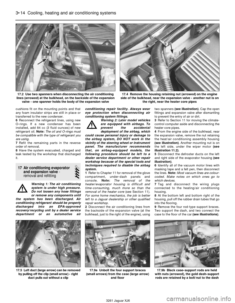
2Disconnect the air conditioning lines from
the backside of the expansion valve (at the
bulkhead, just to the right of the engine), usingtwo spanners (see illustration). Cap the open
fittings and expansion valve after dismantling
to prevent the entry of air or dirt.
3Refer to Section 11 for moving the climate-
control computer aside and disconnecting the
heater core pipes.
4From the engine side of the bulkhead, near
the expansion valve, remove the nut retaining
the heat/air conditioning assembly housing
(see illustration). Another mounting nut is on
the left side, under the wiper motor (see
illustration 11.2).
5Disconnect the defroster ducts on the left
and right side of the evaporator housing (see
illustration).
6Identify all of the vacuum motor lines with
masking tape and a felt pen, then disconnect
the lines. Note:Most vacuum lines are colour-
coded. Make notes on which ones go to
which devices.
7Tag and disconnect the wiring plugs
connected to the heating/air conditioning
housing.
8At the bottom left and bottom right of the
housing, pull off the rubber drain tubes that go
into the flooring.
9Remove the four rod-type support braces.
Two support the dash, and two connect the
case to the floor of the car (see illustrations).
3•14 Cooling, heating and air conditioning systems
17.5 Left duct (large arrow) can be removed
by pulling off the clip (small arrow) - right
duct pulls out without a clip17.9a Unbolt the four support braces
(small arrows) from the case (large arrow)
and floor17.9b Black case-support rods are held
with nuts (arrowed), the gold dash-support
rods are retained by a bolt/nut to the dash
3261 Jaguar XJ6 17.2 Use two spanners when disconnecting the air conditioning
lines (arrowed) at the bulkhead, on the backside of the expansion
valve - one spanner holds the body of the expansion valve
17.4 Remove the housing retaining nut (arrowed) on the engine
side of the bulkhead, near the expansion valve - another nut is on
the right, near the heater core pipes
Page 90 of 227
special electrical device that provides circuit
protection by switching off the ignition and
fuel pump upon impact in the event of vehicle
collision. Later Jaguar models are equipped
with an additional specialised inertia switch.
This later device switches OFF all ignition fed
circuits, locks the fuel filler cap, locks the boot
(only if doors are locked) and unlocks the
doors if they are locked during the accident.
All these functions are directed by the inertia
switch. The inertia switch is located behind
the left kick panel. Refer to Chapter 12 for
more information.
Exhaust system
The exhaust system includes an exhaust
manifold equipped with an exhaust oxygen
sensor, a catalytic converter, an exhaust pipe,
and a silencer.
The catalytic converter is an emission
control device added to the exhaust system to
reduce pollutants. A single-bed converter is
used in combination with a three-way
(reduction) catalyst. See Chapter 6 for more
information regarding the catalytic converter.
2 Fuel pressure relief
1
Warning: Petrol is extremely
flammable, so take extra
precautions when you work on
any part of the fuel system.
Don’t smoke or allow open flames or bare
light bulbs near the work area, and don’t
work in a garage where a natural gas-type
appliance (such as a water heater or a
clothes dryer) with a pilot light is present.
Since petrol is carcinogenic, wear latex
gloves when there’s a possibility of being
exposed to fuel, and, if you spill any fuel on
your skin, rinse it off immediately with soap
and water. Mop up any spills immediately
and do not store fuel-soaked rags wherethey could ignite. The fuel system is under
constant pressure, so, if any fuel lines are
to be disconnected, the fuel pressure in
the system must be relieved first. When
you perform any kind of work on the fuel
system, wear safety glasses and have a
Class B type fire extinguisher on hand.
1Before servicing any fuel system
component, you must relieve the fuel pressure
to minimise the risk of fire or personal injury.
2Remove the fuel filler cap - this will relieve
any pressure built up in the tank.
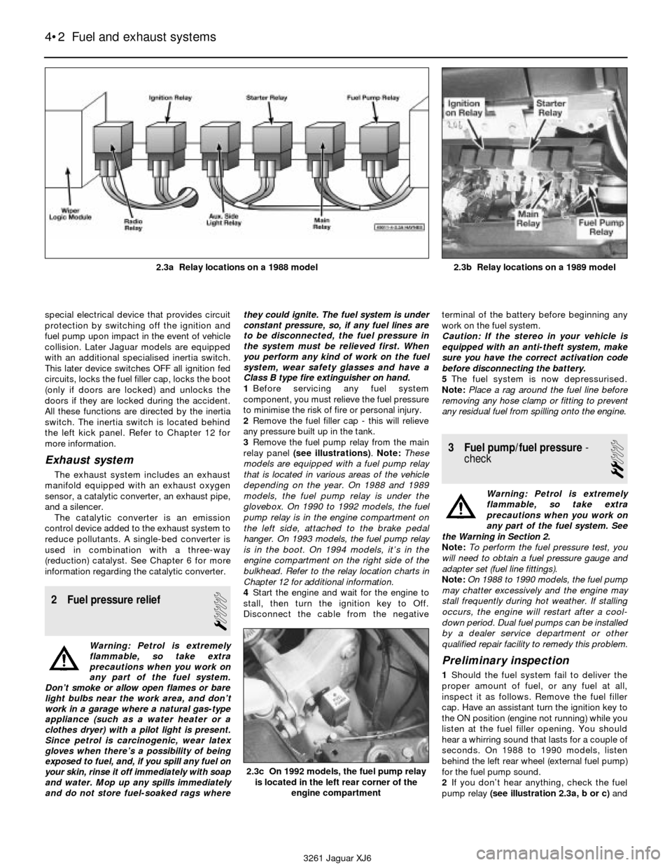
3Remove the fuel pump relay from the main
relay panel (see illustrations). Note:These
models are equipped with a fuel pump relay
that is located in various areas of the vehicle
depending on the year. On 1988 and 1989
models, the fuel pump relay is under the
glovebox. On 1990 to 1992 models, the fuel
pump relay is in the engine compartment on
the left side, attached to the brake pedal
hanger. On 1993 models, the fuel pump relay
is in the boot. On 1994 models, it’s in the
engine compartment on the right side of the
bulkhead. Refer to the relay location charts in
Chapter 12 for additional information.
4Start the engine and wait for the engine to
stall, then turn the ignition key to Off.
Disconnect the cable from the negativeterminal of the battery before beginning any
work on the fuel system.
Caution: If the stereo in your vehicle is
equipped with an anti-theft system, make
sure you have the correct activation code
before disconnecting the battery.
5The fuel system is now depressurised.
Note:Place a rag around the fuel line before
removing any hose clamp or fitting to prevent
any residual fuel from spilling onto the engine.
3 Fuel pump/fuel pressure-
check
2
Warning: Petrol is extremely
flammable, so take extra
precautions when you work on
any part of the fuel system. See
the Warning in Section 2.
Note: To perform the fuel pressure test, you
will need to obtain a fuel pressure gauge and
adapter set (fuel line fittings).
Note: On 1988 to 1990 models, the fuel pump
may chatter excessively and the engine may
stall frequently during hot weather. If stalling
occurs, the engine will restart after a cool-
down period. Dual fuel pumps can be installed
by a dealer service department or other
qualified repair facility to remedy this problem.
Preliminary inspection
1Should the fuel system fail to deliver the
proper amount of fuel, or any fuel at all,
inspect it as follows. Remove the fuel filler
cap. Have an assistant turn the ignition key to
the ON position (engine not running) while you
listen at the fuel filler opening. You should
hear a whirring sound that lasts for a couple of
seconds. On 1988 to 1990 models, listen
behind the left rear wheel (external fuel pump)
for the fuel pump sound.
2If you don’t hear anything, check the fuel
pump relay (see illustration 2.3a, b or c)and
4•2 Fuel and exhaust systems
2.3c On 1992 models, the fuel pump relay
is located in the left rear corner of the
engine compartment
3261 Jaguar XJ6 2.3a Relay locations on a 1988 model
2.3b Relay locations on a 1989 model
Page 91 of 227
circuit. If all circuits are intact and not
damaged, check the inertia switch. Note: The
inertia switch is a special device that shuts
down power to the ignition and the fuel pump
in the event of an accident. See Chapter 12 for
checking and resetting procedures for the
inertia switch.
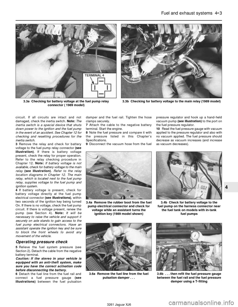
3Remove the relay and check for battery
voltage to the fuel pump relay connector (see
illustration). If there is battery voltage
present, check the relay for proper operation.
Refer to the relay checking procedure in
Chapter 12. Note:If battery voltage is not
available, check for battery voltage to the main
relay(see illustration). Refer to the relay
location diagrams in Chapter 12. The main
relay, which is located next to the fuel pump
relay, supplies voltage to the fuel pump and
ignition system.
4If battery voltage is present, check for
battery voltage directly at the fuel pump
electrical connector (see illustrations), within
two seconds of the ignition key being turned
On. If there is no voltage, check the fuel pump
circuit. If there is voltage present, renew the
pump (see Section 4). Note:It will be
necessary to raise the vehicle and support it
securely on axle stands to gain access to the
fuel pump electrical connectors. Have an
assistant operate the ignition key and be sure
to block the front wheels to avoid any
movement of the vehicle.
Operating pressure check
5Relieve the fuel system pressure (see
Section 2). Detach the cable from the negative
battery terminal.
Caution: If the stereo in your vehicle is
equipped with an anti-theft system, make
sure you have the correct activation code
before disconnecting the battery.
6Detach the fuel line from the fuel rail and
connect a fuel pressure gauge(see
illustrations)between the fuel pulsationdamper and the fuel rail. Tighten the hose
clamps securely.
7Attach the cable to the negative battery
terminal. Start the engine.
8Note the fuel pressure and compare it with
the pressure listed in this Chapter’s
Specifications.
9Disconnect the vacuum hose from the fuelpressure regulator and hook up a hand-held
vacuum pump (see illustration)to the port on
the fuel pressure regulator.
10Read the fuel pressure gauge with vacuum
applied to the pressure regulator and also with
no vacuum applied. The fuel pressure should
decrease as vacuum increases (and increase
as vacuum decreases).
Fuel and exhaust systems 4•3
4
3261 Jaguar XJ6 3.3a Checking for battery voltage at the fuel pump relay
connector ( 1989 model)
3.3b Checking for battery voltage to the main relay (1989 model)
3.6a Remove the fuel line from the fuel
pulsation damper . . .
3.4b Check for battery voltage to the
fuel pump on the harness connector near
the fuel tank on models with in-tank
fuel pumps3.4a Remove the rubber boot from the fuel
pump electrical connector and check for
voltage while an assistant turns the
ignition key (1989 model shown)
3.6b . . . then refit the fuel pressure gauge
between the fuel rail and the fuel pressure
damper using a T-fitting