tow JAGUAR XJ6 1997 2.G Workshop Manual
[x] Cancel search | Manufacturer: JAGUAR, Model Year: 1997, Model line: XJ6, Model: JAGUAR XJ6 1997 2.GPages: 227, PDF Size: 7.2 MB
Page 2 of 227

3261 Jaguar XJ6
LIVING WITH YOUR JAGUAR XJ6
IntroductionPage 0•4
Notes for UK readersPage 0•4
Safety first!Page 0•5
Roadside repairs
IntroductionPage 0•6
If your car won’t startPage 0•6
Jump startingPage 0•7
Wheel changingPage 0•8
Identifying leaksPage 0•9
TowingPage 0•9
Weekly checks
IntroductionPage 0•10
Underbonnet check points Page 0•10
Engine oil levelPage 0•11
Coolant levelPage 0•11
Brake fluid levelPage 0•12
Screen washer fluid level Page 0•12
Power steering fluid level Page 0•13
Wiper bladesPage 0•13
Tyre condition and pressure Page 0•14
BatteryPage 0•15
Bulbs and fusesPage 0•15
Lubricants, fluids and tyre pressuresPage 0•16
MAINTENANCE
Routine maintenance and servicingPage 1•1
Servicing specificationsPage 1•2
Maintenance schedulePage 1•3
Maintenance procedures Page 1•6
Contents
Page 8 of 227
3261 Jaguar XJ6
0•8Roadside repairs
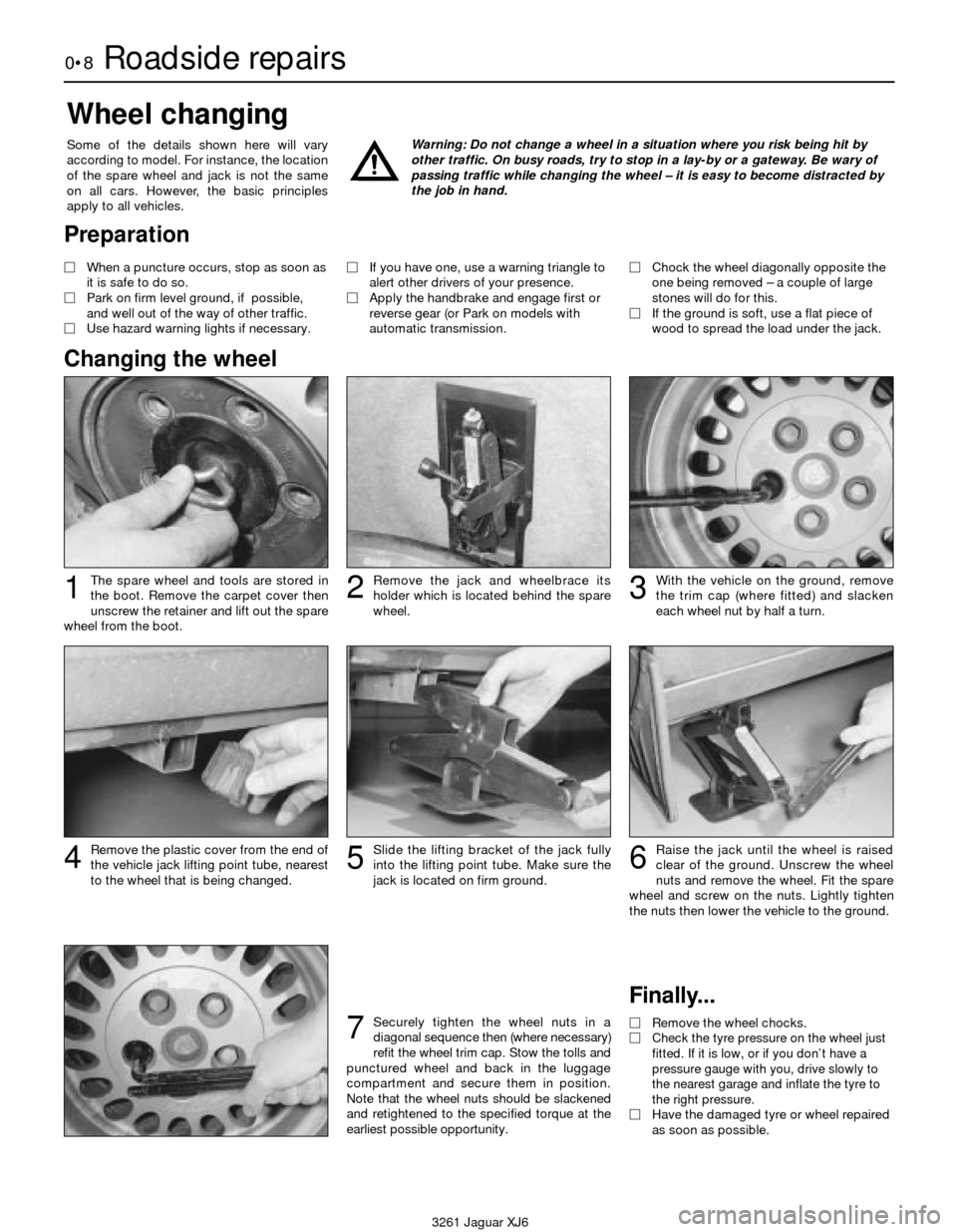
The spare wheel and tools are stored in
the boot. Remove the carpet cover then
unscrew the retainer and lift out the spare
wheel from the boot.
Wheel changing
Some of the details shown here will vary
according to model. For instance, the location
of the spare wheel and jack is not the same
on all cars. However, the basic principles
apply to all vehicles.Warning: Do not change a wheel in a situation where you risk being hit by
other traffic. On busy roads, try to stop in a lay-by or a gateway. Be wary of
passing traffic while changing the wheel – it is easy to become distracted by
the job in hand.
Finally...
MRemove the wheel chocks.
MCheck the tyre pressure on the wheel just
fitted. If it is low, or if you don’t have a
pressure gauge with you, drive slowly to
the nearest garage and inflate the tyre to
the right pressure.
MHave the damaged tyre or wheel repaired
as soon as possible.
Remove the plastic cover from the end of
the vehicle jack lifting point tube, nearest
to the wheel that is being changed.Slide the lifting bracket of the jack fully
into the lifting point tube. Make sure the
jack is located on firm ground.Raise the jack until the wheel is raised
clear of the ground. Unscrew the wheel
nuts and remove the wheel. Fit the spare
wheel and screw on the nuts. Lightly tighten
the nuts then lower the vehicle to the ground.
With the vehicle on the ground, remove
the trim cap (where fitted) and slacken
each wheel nut by half a turn.Remove the jack and wheelbrace its
holder which is located behind the spare
wheel.123
4
Securely tighten the wheel nuts in a
diagonal sequence then (where necessary)
refit the wheel trim cap. Stow the tolls and
punctured wheel and back in the luggage
compartment and secure them in position.
Note that the wheel nuts should be slackened
and retightened to the specified torque at the
earliest possible opportunity.7
56
Preparation
MWhen a puncture occurs, stop as soon as
it is safe to do so.
MPark on firm level ground, if possible,
and well out of the way of other traffic.
MUse hazard warning lights if necessary. MIf you have one, use a warning triangle to
alert other drivers of your presence.
MApply the handbrake and engage first or
reverse gear (or Park on models with
automatic transmission.MChock the wheel diagonally opposite the
one being removed – a couple of large
stones will do for this.
MIf the ground is soft, use a flat piece of
wood to spread the load under the jack.
Changing the wheel
Page 9 of 227
3261 Jaguar XJ6
Roadside repairs0•9
When all else fails, you may find yourself
having to get a tow home – or of course you
may be helping somebody else. Long-distance
recovery should only be done by a garage or
breakdown service. For shorter distances, DIY
towing using another car is easy enough, but
observe the following points:
MUse a proper tow-rope – they are not
expensive. The vehicle being towed must
display an ‘ON TOW’ sign in its rear window.
MAlways turn the ignition key to the ‘on’
position when the vehicle is being towed, so
that the steering lock is released, and that the
direction indicator and brake lights will work.
MOnly attach the tow-rope to the towing
eyes provided. On some models with energy-
absorbing bumpers there are no front towing
eyes; on these vehicles the tow-rope shouldbe attached around the rear arm of the lower
control arm so that the rope passes on the
inside of the coil spring.
MBefore being towed, release the handbrake
and select neutral on the transmission.
MNote that greater-than-usual pedal
pressure will be required to operate the
brakes, since the vacuum servo unit is only
operational with the engine running.
MOn models with power steering, greater-
than-usual steering effort will also be required.
MThe driver of the car being towed must
keep the tow-rope taut at all times to avoid
snatching.
MMake sure that both drivers know the route
before setting off.
MOnly drive at moderate speeds and keep
the distance towed to a minimum. Drivesmoothly and allow plenty of time for slowing
down at junctions.
MOn models with automatic transmission,
special precautions apply. If in doubt, do not
tow, or transmission damage may result.
Caution: On models with automatic
transmission, if the vehicle is to be towed
with its rear wheels on the ground, and
extra 1.7 litres of fluid should be added to
the transmission, prior to towing (this extra
fluid must be drained before driving the
vehicle). Even with the extra fluid added to
the transmission, do not tow the vehicle at
speeds in excess of 30 mph (50 kmh) or for
a distance of greater than 15 miles (25 km).
If towing speed/distance are to exceed
these limits, then the vehicle must be
towed with its rear wheels off the ground.
Towing
Puddles on the garage floor or drive, or
obvious wetness under the bonnet or
underneath the car, suggest a leak that needs
investigating. It can sometimes be difficult to
decide where the leak is coming from,
especially if the engine bay is very dirty
already. Leaking oil or fluid can also be blown
rearwards by the passage of air under the car,
giving a false impression of where the
problem lies.Warning: Most automotive oils
and fluids are poisonous. Wash
them off skin, and change out of
contaminated clothing, without
delay.The smell of a fluid leaking
from the car may provide a
clue to what’s leaking. Some
fluids are distinctively
coloured. It may help to clean the car and
to park it over some clean paper as an
aid to locating the source of the leak.
Remember that some leaks may only
occur while the engine is running.
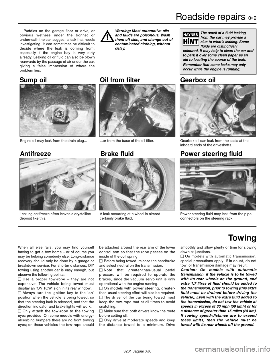
Sump oil Gearbox oil
Brake fluid
Power steering fluid
Oil from filter
Antifreeze
Engine oil may leak from the drain plug......or from the base of the oil filter.
Leaking antifreeze often leaves a crystalline
deposit like this.Gearbox oil can leak from the seals at the
inboard ends of the driveshafts.
A leak occurring at a wheel is almost
certainly brake fluid.Power steering fluid may leak from the pipe
connectors on the steering rack.
Page 11 of 227
3261 Jaguar XJ6
Weekly checks0•11
Engine oil level
Before you start
4Make sure that your car is on level ground.
4Check the oil level before the car is driven,
or at least 5 minutes after the engine has been
switched off.
The correct oilModern engines place great demands on their
oil. It is very important that the correct oil for
your car is used (See “Lubricants, fluids and
tyre pressures”).
Car care
l If you have to add oil frequently, you should
check whether you have any oil leaks. Place
some clean paper under the car overnight,
and check for stains in the morning. If there
are no leaks, the engine may be burning oil
(see “Fault finding”).
lAlways maintain the level between the
upper and lower dipstick marks (see photo 3).
If the level is too low severe engine damage
may occur. Oil seal failure may result if the
engine is overfilled by adding too much oil.
If the oil level is checked
immediately after driving the
vehicle, some of the oil will
remain in the upper engine
components, resulting in an inaccurate
reading on the dipstick!
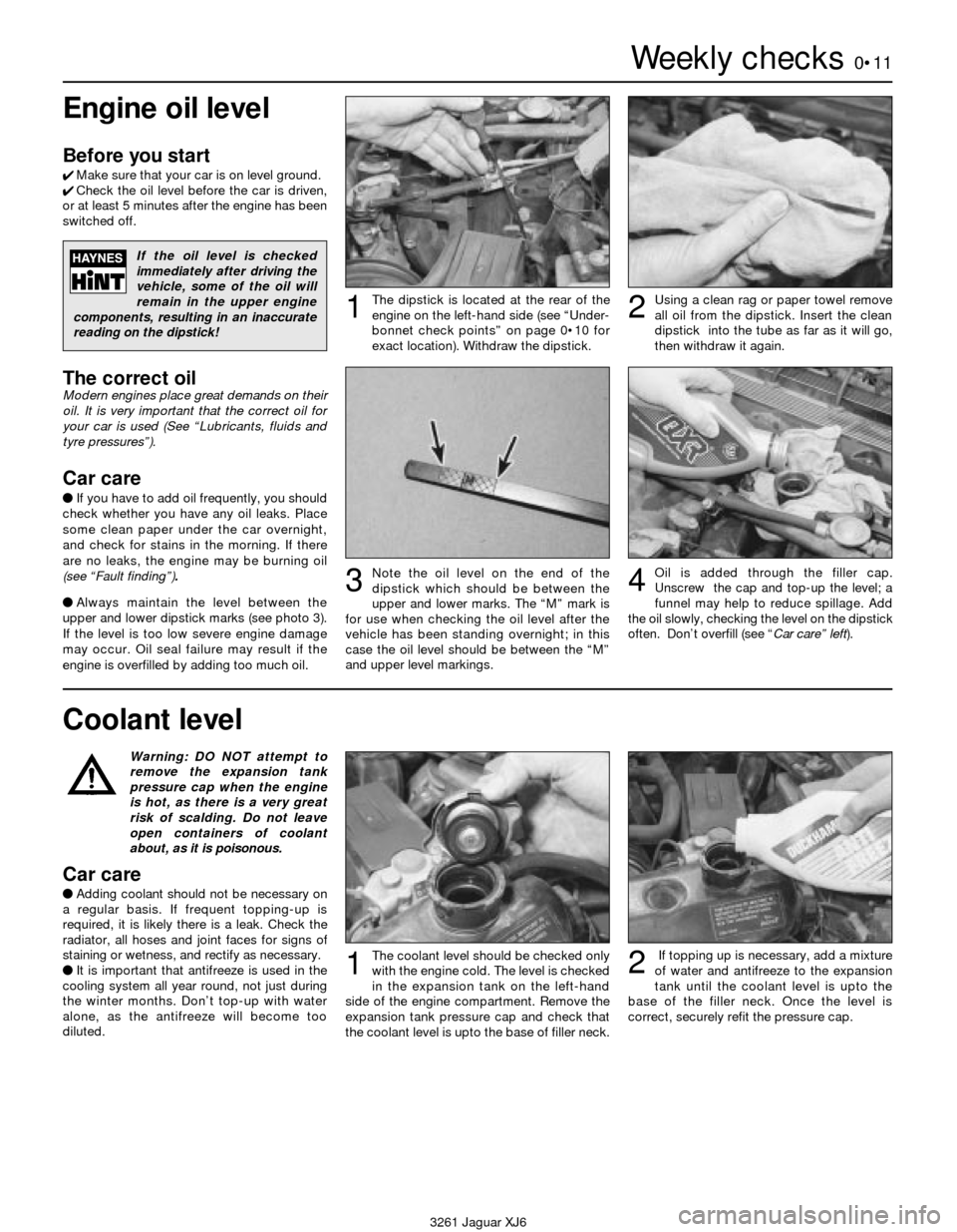
The dipstick is located at the rear of the
engine on the left-hand side (see “Under-
bonnet check points” on page 0•10 for
exact location). Withdraw the dipstick.Using a clean rag or paper towel remove
all oil from the dipstick. Insert the clean
dipstick into the tube as far as it will go,
then withdraw it again.
Note the oil level on the end of the
dipstick which should be between the
upper and lower marks. The “M” mark is
for use when checking the oil level after the
vehicle has been standing overnight; in this
case the oil level should be between the “M”
and upper level markings.Oil is added through the filler cap.
Unscrew the cap and top-up the level; a
funnel may help to reduce spillage. Add
the oil slowly, checking the level on the dipstick
often. Don’t overfill (see “Car care” left).
12
34
Warning: DO NOT attempt to
remove the expansion tank
pressure cap when the engine
is hot, as there is a very great
risk of scalding. Do not leave
open containers of coolant
about, as it is poisonous.
Car care
lAdding coolant should not be necessary on
a regular basis. If frequent topping-up is
required, it is likely there is a leak. Check the
radiator, all hoses and joint faces for signs of
staining or wetness, and rectify as necessary.
lIt is important that antifreeze is used in the
cooling system all year round, not just during
the winter months. Don’t top-up with water
alone, as the antifreeze will become too
diluted.
Coolant level
The coolant level should be checked only
with the engine cold. The level is checked
in the expansion tank on the left-hand
side of the engine compartment. Remove the
expansion tank pressure cap and check that
the coolant level is upto the base of filler neck.If topping up is necessary, add a mixture
of water and antifreeze to the expansion
tank until the coolant level is upto the
base of the filler neck. Once the level is
correct, securely refit the pressure cap.12
Page 29 of 227
position, a worn or weak shock absorber is
probably the reason.
4Repeat the above check at each of the
three remaining corners of the vehicle.
Under the vehicle
5Raise the vehicle with a trolley jack and
support it securely on axle stands. See
“Jacking and towing”for proper jacking
points.
6Check the shock absorbers for evidence of
fluid leakage. Make sure that any fluid noted is
from the shocks and not from any other
source. Also check the rubber mounts at each
end for deterioration If the shock absorbers
fail any of the tests above replace the shocks
as a set.
7Check the tyres for irregular wear patterns
and proper inflation. See “Weekly checks”for
information regarding tyre wear.
8Inspect the universal joint between the
steering shaft and the steering gear housing.
Check the steering gear housing for grease
leakage. Make sure that the dust seals and
boots are not damaged and that the boot
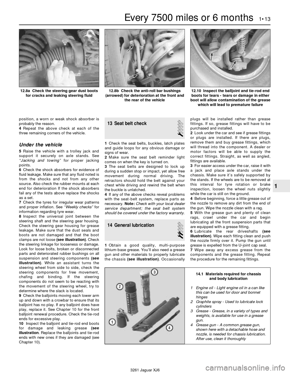
clamps are not loose (see illustration). Check
the steering linkage for looseness or damage.
Look for loose bolts, broken or disconnected
parts and deteriorated rubber bushings on all
suspension and steering components (see
illustration). While an assistant turns the
steering wheel from side to side, check the
steering components for free movement,
chafing and binding. If the steering
components do not seem to be reacting with
the movement of the steering wheel, try to
determine where the slack is located.
9Check the balljoints moving each lower arm
up and down with a crowbar to ensure that its
balljoint has no play. If any balljoint does have
play, replace it. See Chapter 10 for the front
balljoint renewal procedure. Check the tie-rod
ends for excessive play.
10Inspect the balljoint and tie-rod end boots
for damage and leaking grease (see
illustration. Replace the balljoints and tie-rod
ends with new ones if they are damaged (see
Chapter 10).
13 Seat belt check
1
1Check the seat belts, buckles, latch plates
and guide loops for any obvious damage or
signs of wear.
2Make sure the seat belt reminder light
comes on when the key is turned on.
3The seat belts are designed to lock up
during a sudden stop or impact, yet allow free
movement during normal driving. The
retractors should hold the belt against your
chest while driving and rewind the belt when
the buckle is unlatched.
4If any of the above checks reveal problems
with the seat-belt system, replace parts as
necessary.Note:Check with your local dealer
service department; the seat belt system
should be covered under the factory warranty.
14 General lubrication
2
1Obtain a good quality, multi-purpose
lithium-base grease. You’ll also need a grease
gun and other materials to properly lubricate
the chassis (see illustration). Occasionallyplugs will be installed rather than grease
fittings. If so, grease fittings will have to be
purchased and installed.
2Look under the car and see if grease fittings
or plugs are installed. If there are plugs,
remove them and buy grease fittings, which
will thread into the component. A dealer or
motor factors will be able to supply the
correct fittings. Straight, as well as angled,
fittings are available.
3For easier access under the car, raise it with
a jack and place axle stands under the
chassis. Make sure it’s safely supported by
the stands. If the wheels are to be removed at
this interval for tyre rotation or brake
inspection, loosen the wheel nuts slightly
while the car is still on the ground.
4Before beginning, force a little grease out of
the nozzle to remove any dirt from the end of
the gun. Wipe the nozzle clean with a rag.
5With the grease gun and plenty of clean
rags, crawl under the car and begin
lubricating all the front suspension parts that
are equipped with a grease fitting.
6Lubricate the rear driveshafts (see
illustration). Wipe each fitting clean and push
the nozzle firmly over it. Pump the gun until
grease is expelled from the U-joint cap seal.
7Wipe away any excess grease from the
components and the grease fitting. Repeat
the procedure for the remaining fittings.
Every 7500 miles or 6 months 1•13
1
14.1 Materials required for chassis
and body lubrication
3261 Jaguar XJ6 12.8a Check the steering gear dust boots
for cracks and leaking steering fluid
12.8b Check the anti-roll bar bushings
(arrowed) for deterioration at the front and
the rear of the vehicle12.10 Inspect the balljoint and tie-rod end
boots for tears - tears or damage in either
boot will allow contamination of the grease
which will lead to premature failure
1 Engine oil - Light engine oil in a can like
this can be used for door and bonnet
hinges
2 Graphite spray - Used to lubricate lock
cylinders
3 Grease - Grease, in a variety of types and
weights, is available for use in a grease
gun.
4 Grease gun - A common grease gun,
shown here with a detachable hose and
nozzle, is needed for chassis lubrication.
After use, clean it thoroughly
Page 31 of 227
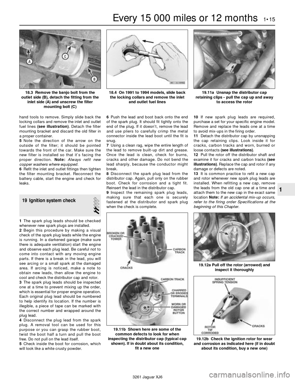
hand tools to remove. Simply slide back the
locking collars and remove the inlet and outlet
fuel lines (see illustration). Detach the filter
mounting bracket and discard the old filter in
a proper container.
5Note the direction of the arrow on the
outside of the filter; it should be pointed
towards the front of the car. Make sure the
new filter is installed so that it’s facing the
proper direction. Note:Always refit new
copper washers where equipped.
6Refit the inlet and outlet fittings then tighten
the filter mounting bracket. Reconnect the
battery cable, start the engine and check for
leaks.
19 Ignition system check
2
1The spark plug leads should be checked
whenever new spark plugs are installed.
2Begin this procedure by making a visual
check of the spark plug leads while the engine
is running. In a darkened garage (make sure
there is adequate ventilation) start the engine
and observe each plug lead. Be careful not to
come into contact with any moving engine
parts. If there is a break in the lead, you will
see arcing or a small spark at the damaged
area. If arcing is noticed, make a note to
obtain new leads, then allow the engine to
cool and check the distributor cap and rotor.
3The spark plug leads should be inspected
one at a time to prevent mixing up the order,
which is essential for proper engine operation.
Each original plug lead should be numbered
to help identify its location. If the number is
illegible, a piece of tape can be marked with
the correct number and wrapped around the
plug lead.
4Disconnect the plug lead from the spark
plug. A removal tool can be used for this
purpose or you can grasp the rubber boot,
twist the boot half a turn and pull the boot
free. Do not pull on the lead itself.
5Check inside the boot for corrosion, which
will look like a white crusty powder.6Push the lead and boot back onto the end
of the spark plug. It should fit tightly onto the
end of the plug. If it doesn’t, remove the lead
and use pliers to carefully crimp the metal
connector inside the lead boot until the fit is
snug.
7Using a clean rag, wipe the entire length of
the lead to remove built-up dirt and grease.
Once the lead is clean, check for burns,
cracks and other damage. Do not bend the
lead sharply, because the conductor might
break.
8Disconnect the spark plug lead from the
distributor cap. Again, pull only on the rubber
boot. Check for corrosion and a tight fit.
Reinsert the lead in the distributor cap.
9Inspect the remaining spark plug leads,
making sure that each one is securely
fastened at the distributor and spark plug
when the check is complete.10If new spark plug leads are required,
purchase a set for your specific engine model.
Remove and replace the leads one at a time
to avoid mix-ups in the firing order.
11Detach the distributor cap by unsnapping
the cap retaining clips. Look inside it for
cracks, carbon tracks and worn, burned or
loose contacts (see illustrations).
12Pull the rotor off the distributor shaft and
examine it for cracks and carbon tracks (see
illustrations). Replace the cap and rotor if any
damage or defects are noted.
13It is common practice to refit a new cap
and rotor whenever new spark plug leads are
installed. When refitting a new cap, remove
the leads from the old cap one at a time and
attach them to the new cap in the exact same
location Note:If an accidental mix-up occurs,
refer to the firing order Specifications at the
beginning of this Chapter.
Every 15 000 miles or 12 months 1•15
1
19.11a Unsnap the distributor cap
retaining clips - pull the cap up and away
to access the rotor
19.11b Shown here are some of the
common defects to look for when
inspecting the distributor cap (typical cap
shown). If in doubt about its condition,
fit a new one
19.12a Pull off the rotor (arrowed) and
inspect it thoroughly
19.12b Check the ignition rotor for wear
and corrosion as indicated here (if in doubt
about its condition, buy a new one)
3261 Jaguar XJ6 18.3 Remove the banjo bolt from the
outlet side (B), detach the fitting from the
inlet side (A) and unscrew the filter
mounting bolt (C)
18.4 On 1991 to 1994 models, slide back
the locking collars and remove the inlet
and outlet fuel lines
Page 32 of 227
20 Crankcase ventilation
system check
1
Refer to Chapter 6.
21 Drivebelt check and renewal
2
Check
1The drivebelts, or V-belts as they are
sometimes called, are located at the front of
the engine and play an important role in the
overall operation of the vehicle and its
components. Due to their function and
material make-up, the belts are prone to
failure after a period of time and should be
inspected and adjusted periodically to prevent
major engine damage.
2The number of belts used on a particular
vehicle depends on the accessories installed.
The main belt transmits power from the
crankshaft to the water pump, alternator and
the power steering pump. The second belt
transmits power from the crankshaft to the air
conditioning compressor.
3With the engine off, open the bonnet and
locate the drivebelts. With a flashlight, check
each belt for separation of the adhesive
rubber on both sides of the core, core
separation from the belt side, a severed core,
separation of the ribs from the adhesive
rubber, cracking or separation of the ribs, and
torn or worn ribs or cracks in the inner ridges
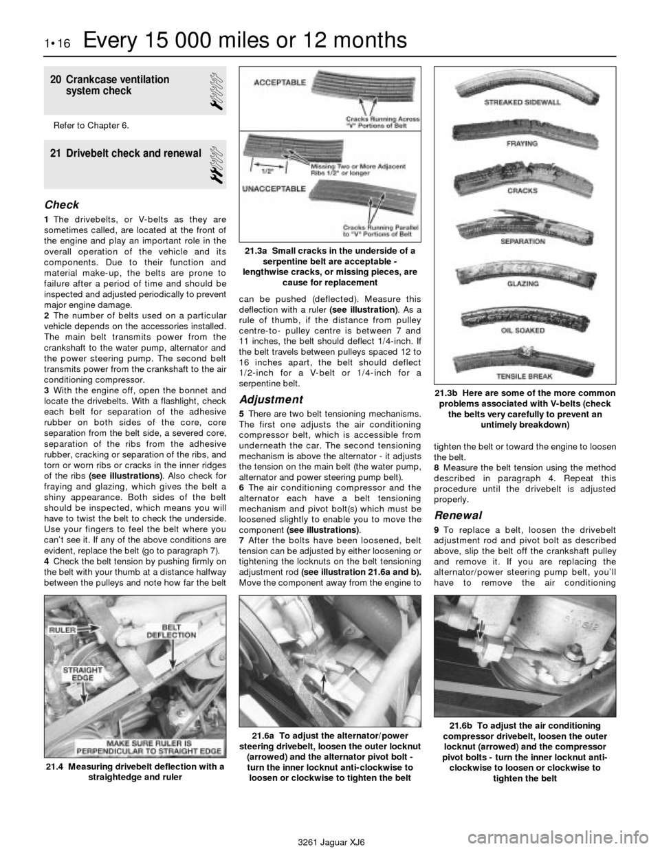
of the ribs (see illustrations). Also check for
fraying and glazing, which gives the belt a
shiny appearance. Both sides of the belt
should be inspected, which means you will
have to twist the belt to check the underside.
Use your fingers to feel the belt where you
can’t see it. If any of the above conditions are
evident, replace the belt (go to paragraph 7).
4Check the belt tension by pushing firmly on
the belt with your thumb at a distance halfway
between the pulleys and note how far the beltcan be pushed (deflected). Measure this
deflection with a ruler (see illustration). As a
rule of thumb, if the distance from pulley
centre-to- pulley centre is between 7 and
11 inches, the belt should deflect 1/4-inch. If
the belt travels between pulleys spaced 12 to
16 inches apart, the belt should deflect
1/2-inch for a V-belt or 1/4-inch for a
serpentine belt.
Adjustment
5There are two belt tensioning mechanisms.
The first one adjusts the air conditioning
compressor belt, which is accessible from
underneath the car. The second tensioning
mechanism is above the alternator - it adjusts
the tension on the main belt (the water pump,
alternator and power steering pump belt).
6The air conditioning compressor and the
alternator each have a belt tensioning
mechanism and pivot bolt(s) which must be
loosened slightly to enable you to move the
component (see illustrations).
7After the bolts have been loosened, belt
tension can be adjusted by either loosening or
tightening the locknuts on the belt tensioning
adjustment rod (see illustration 21.6a and b).
Move the component away from the engine totighten the belt or toward the engine to loosen
the belt.
8Measure the belt tension using the method
described in paragraph 4. Repeat this
procedure until the drivebelt is adjusted
properly.
Renewal
9To replace a belt, loosen the drivebelt
adjustment rod and pivot bolt as described
above, slip the belt off the crankshaft pulley
and remove it. If you are replacing the
alternator/power steering pump belt, you’ll
have to remove the air conditioning
1•16Every 15 000 miles or 12 months
21.3a Small cracks in the underside of a
serpentine belt are acceptable -
lengthwise cracks, or missing pieces, are
cause for replacement
21.3b Here are some of the more common
problems associated with V-belts (check
the belts very carefully to prevent an
untimely breakdown)
21.4 Measuring drivebelt deflection with a
straightedge and ruler
21.6a To adjust the alternator/power
steering drivebelt, loosen the outer locknut
(arrowed) and the alternator pivot bolt -
turn the inner locknut anti-clockwise to
loosen or clockwise to tighten the belt21.6b To adjust the air conditioning
compressor drivebelt, loosen the outer
locknut (arrowed) and the compressor
pivot bolts - turn the inner locknut anti-
clockwise to loosen or clockwise to
tighten the belt
3261 Jaguar XJ6
Page 41 of 227
8Tighten the screws to the torque listed in
this Chapter’s Specifications in three or four
equal steps.
9Refit the remaining components, start the
engine and check for oil leaks.
5 Intake manifold-
removal and refitting
2
Removal
1Disconnect the negative cable from the
battery.
Caution: If the stereo in your vehicle is
equipped with an anti-theft system, make
sure you have the correct activation code
before disconnecting the battery.
2Refer to Chapter 4 to remove the
accelerator and cruise-control linkage, safely
relieve the fuel system pressure, and
disconnect the fuel supply lines.
3Label or mark and detach the PCV and
vacuum hoses connected to the intake
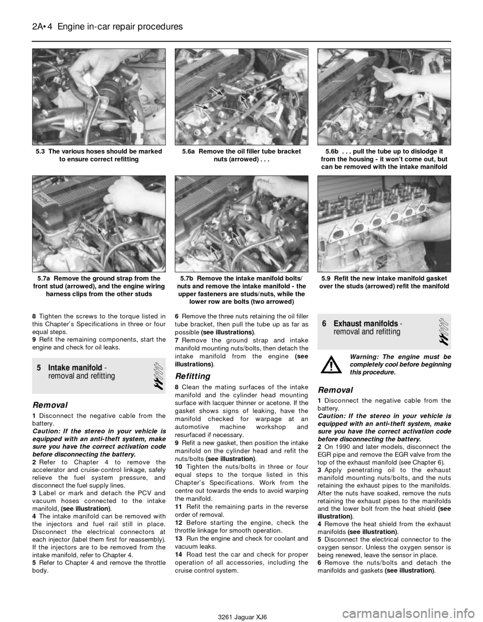
manifold, (see illustration).
4The intake manifold can be removed with
the injectors and fuel rail still in place.
Disconnect the electrical connectors at
each injector (label them first for reassembly).
If the injectors are to be removed from the
intake manifold, refer to Chapter 4.
5Refer to Chapter 4 and remove the throttle
body.6Remove the three nuts retaining the oil filler
tube bracket, then pull the tube up as far as
possible (see illustrations).
7Remove the ground strap and intake
manifold mounting nuts/bolts, then detach the
intake manifold from the engine (see
illustrations).
Refitting
8Clean the mating surfaces of the intake
manifold and the cylinder head mounting
surface with lacquer thinner or acetone. If the
gasket shows signs of leaking, have the
manifold checked for warpage at an
automotive machine workshop and
resurfaced if necessary.
9Refit a new gasket, then position the intake
manifold on the cylinder head and refit the
nuts/bolts (see illustration).
10Tighten the nuts/bolts in three or four
equal steps to the torque listed in this
Chapter’s Specifications. Work from the
centre out towards the ends to avoid warping
the manifold.
11Refit the remaining parts in the reverse
order of removal.
12Before starting the engine, check the
throttle linkage for smooth operation.
13Run the engine and check for coolant and
vacuum leaks.
14Road test the car and check for proper
operation of all accessories, including the
cruise control system.
6 Exhaust manifolds-
removal and refitting
2
Warning: The engine must be
completely cool before beginning
this procedure.
Removal
1Disconnect the negative cable from the
battery.
Caution: If the stereo in your vehicle is
equipped with an anti-theft system, make
sure you have the correct activation code
before disconnecting the battery.
2On 1990 and later models, disconnect the
EGR pipe and remove the EGR valve from the
top of the exhaust manifold (see Chapter 6).
3Apply penetrating oil to the exhaust
manifold mounting nuts/bolts, and the nuts
retaining the exhaust pipes to the manifolds.
After the nuts have soaked, remove the nuts
retaining the exhaust pipes to the manifolds
and the lower bolt from the heat shield (see
illustration).
4Remove the heat shield from the exhaust
manifolds(see illustration).
5Disconnect the electrical connector to the
oxygen sensor. Unless the oxygen sensor is
being renewed, leave the sensor in place.
6Remove the nuts/bolts and detach the
manifolds and gaskets (see illustration).
2A•4 Engine in-car repair procedures
5.3 The various hoses should be marked
to ensure correct refitting5.6a Remove the oil filler tube bracket
nuts (arrowed) . . .5.6b . . . pull the tube up to dislodge it
from the housing - it won’t come out, but
can be removed with the intake manifold
5.7a Remove the ground strap from the
front stud (arrowed), and the engine wiring
harness clips from the other studs5.7b Remove the intake manifold bolts/
nuts and remove the intake manifold - the
upper fasteners are studs/nuts, while the
lower row are bolts (two arrowed)5.9 Refit the new intake manifold gasket
over the studs (arrowed) refit the manifold
3261 Jaguar XJ6
Page 42 of 227
Refitting
7Use a scraper to remove all traces of old
gasket material and carbon deposits from the
manifold and cylinder head mating surfaces. If
the gasket was leaking, have the manifold
checked for warpage at an automotive
machine workshop and resurfaced if
necessary.
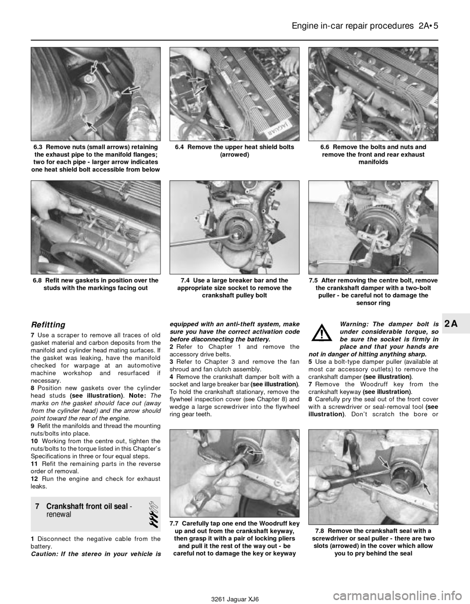
8Position new gaskets over the cylinder
head studs (see illustration). Note:The
marks on the gasket should face out (away
from the cylinder head) and the arrow should
point toward the rear of the engine.
9Refit the manifolds and thread the mounting
nuts/bolts into place.
10Working from the centre out, tighten the
nuts/bolts to the torque listed in this Chapter’s
Specifications in three or four equal steps.
11Refit the remaining parts in the reverse
order of removal.
12Run the engine and check for exhaust
leaks.
7 Crankshaft front oil seal-
renewal
3
1Disconnect the negative cable from the
battery.
Caution: If the stereo in your vehicle isequipped with an anti-theft system, make
sure you have the correct activation code
before disconnecting the battery.
2Refer to Chapter 1 and remove the
accessory drive belts.
3Refer to Chapter 3 and remove the fan
shroud and fan clutch assembly.
4Remove the crankshaft damper bolt with a
socket and large breaker bar (see illustration).
To hold the crankshaft stationary, remove the
flywheel inspection cover (see Chapter 8) and
wedge a large screwdriver into the flywheel
ring gear teeth. Warning: The damper bolt is
under considerable torque, so
be sure the socket is firmly in
place and that your hands are
not in danger of hitting anything sharp.
5Use a bolt-type damper puller (available at
most car accessory outlets) to remove the
crankshaft damper (see illustration).
7Remove the Woodruff key from the
crankshaft keyway (see illustration).
8Carefully pry the seal out of the front cover
with a screwdriver or seal-removal tool(see
illustration). Don’t scratch the bore or
Engine in-car repair procedures 2A•5
2A
6.3 Remove nuts (small arrows) retaining
the exhaust pipe to the manifold flanges;
two for each pipe - larger arrow indicates
one heat shield bolt accessible from below6.4 Remove the upper heat shield bolts
(arrowed)6.6 Remove the bolts and nuts and
remove the front and rear exhaust
manifolds
6.8 Refit new gaskets in position over the
studs with the markings facing out
7.7 Carefully tap one end the Woodruff key
up and out from the crankshaft keyway,
then grasp it with a pair of locking pliers
and pull it the rest of the way out - be
careful not to damage the key or keyway7.8 Remove the crankshaft seal with a
screwdriver or seal puller - there are two
slots (arrowed) in the cover which allow
you to pry behind the seal
7.4 Use a large breaker bar and the
appropriate size socket to remove the
crankshaft pulley bolt7.5 After removing the centre bolt, remove
the crankshaft damper with a two-bolt
puller - be careful not to damage the
sensor ring
3261 Jaguar XJ6
Page 46 of 227

2Refer to Section 8 and remove the front
cover and upper and lower timing chains.
3Remove the power steering drive coupling
from the auxiliary shaft (see illustration).
4Use a small drill to drill holes in the oil seal,
then use a slide-hammer puller to remove the
seal from the rear of the auxiliary shaft
housing (see illustration).
Caution: Drill straight and carefully to avoid
damaging the auxiliary shaft.
5Use a pair of snap-ring pliers to remove the
snap ring from the rear of the auxiliary shaft
(see illustration).
6Pull the auxiliary shaft out toward the front
of the engine.
7Remove the three internal hex-head bolts
and the auxiliary shaft housing.
8Examine the surface of the auxiliary shaft,
it’s sprocket, and the distributor drive-gear. If
there is noticeable wear or damage, replace
the auxiliary shaft assembly with a new one
(see illustration).
9If the auxiliary shaft housing has been
removed, clean it, scrape away the old gasket
material from the housing and the engine
block and refit the housing with a new gasket
(see illustration).
10Clean the auxiliary shaft, lubricate it with
engine oil and refit it through the front of the
block, then refit the washer (see illustration).
Refit the snap-ring(refer to illustration 9.4).11The new oil seal for the rear of the auxiliary
shaft comes with a plastic refitting sleeve that
keeps the seal lip from folding back during
refitting. Keep this sleeve in place until the seal
is fully installed. Tap the new seal into the
housing with a hammer and appropriate-size
socket until the seal is flush, then remove the
plastic sleeve (see illustration).
12The remainder of the refitting is the
reverse of removal. Note:When refitting the
distributor (see Chapter 5), use a new O-ring
to prevent oil leaks at the distributor.
13Run the engine and check for oil leaks at
the power steering pump-to-housing interface.10 Camshafts and valve lifters-
removal, inspection and
refitting
4
Removal
Note:The renewal of the camshafts requires
the use of several special tools. Read through
the procedure and acquire the special tools,
or their equivalent, before beginning work.
1Remove the valve cover (see Section 4).
2Refer to Section 3 and position the engine
at TDC for number 1 cylinder.
3Refer to Chapter 5 and remove the
distributor cap and set it aside along with the
spark plug leads. Mark the positions of the
distributor body and rotor.
4Using a feeler gauge, measure and record
the clearance between the intake and exhaust
camshaft lobes and the lifters for cylinder
number 1 (see illustration). Rotate the
crankshaft until the next cylinder in the firing
order is at TDC and check and record the
valve clearance for that cylinder. Following the
firing order, check and record the valve
clearance for the remaining valves with the
appropriate cylinder at TDC.
5Return the engine to TDC for cylinder
number 1. Using the special tool (Jaguar tool
no. 18G 1433), check the position of each
Engine in-car repair procedures 2A•9
2A
9.3 Use a screwdriver to hold the drive
coupling (arrowed) stationary while
removing the bolt9.4 Remove the auxiliary shaft seal with a
small slide-hammer puller9.5 Use snap-ring pliers to remove the
snap ring (arrowed) from the shaft - note
the three internal hex-head bolts retaining
the housing to the engine block
9.8 Inspect these areas of the auxiliary
shaft for wear
A Oil seal surface
B Bearing journalC Sprocket
D Distributor drive9.9 Refit the auxiliary shaft rear housing
with a new gasket, aligning the oil slot
(arrowed) with the housing
3261 Jaguar XJ6
9.10 Refit the washer before replacing the
snap-ring
9.11 Tap the seal squarely into the bore
with a socket until the seal is flush
with the housing, then remove the
plastic fitting sleeve