Chapter 12 JAGUAR XJ6 1997 2.G Workshop Manual
[x] Cancel search | Manufacturer: JAGUAR, Model Year: 1997, Model line: XJ6, Model: JAGUAR XJ6 1997 2.GPages: 227, PDF Size: 7.2 MB
Page 4 of 227
These models are equipped with dual overhead cam in-line six-
cylinder engines. The engines feature a computer-controlled ignition
system and electronic fuel injection. Transmissions are a four-speed
automatic equipped with a lock-up torque converter. The transmission
is mounted to the back of the engine, and power is transmitted to the
fully independent rear axle through a two-piece propshaft. The
differential is bolted solidly to a frame crossmember and drives the
wheels through driveshafts equipped with inner and outer U-joints.
The front suspension is fitted with upper and lower control arms, coil
springs and shock absorbers. The rear suspension is an independent
type suspension which also have coil spring/shock absorber
assemblies and a lower control arm. The rear driveshaft acts as the
upper control arm.
Power-assisted Anti-lock Brake Systems (ABS) with four-wheel disc
brakes are standard equipment on all Jaguar XJ6 models covered in
this manual. Power rack-and-pinion steering is also standard
equipment.
Your Jaguar manual
The aim of this manual is to help you get the best value from your
vehicle. It can do so in several ways. It can help you decide what work
must be done (even should you choose to get it done by a garage). It
will also provide information on routine maintenance and servicing, and
give a logical course of action and diagnosis when random faults
occur. However, it is hoped that you will use the manual by tackling the
work yourself. On simpler jobs it may even be quicker than booking the
car into a garage and going there twice, to leave and collect it. Perhaps
most important, a lot of money can be saved by avoiding the costs a
garage must charge to cover its labour and overheads.
The manual has drawings and descriptions to show the function of
the various components so that their layout can be understood. Tasks
are described and photographed in a clear step-by-step sequence.
Notes for UK readers
Because this manual was originally written in the US, its layout
differs from our UK-originated manuals. The preliminary and reference
sections have been re-written specifically for the UK market, and the
maintenance schedule has been amended to suit UK vehicles.
However, it will be noticed that some references to componentsremain in the US style; the UK equivalent of US components and
various other US words is given in the Section headed “Use of
English”. It should be remembered that the project vehicle used in the
main Chapters of this manual was a left-hand drive US model;
therefore, the position of the steering wheel, steering column and
pedals, etc. will be on the opposite side of the vehicle on UK models.
References to “right” and “left” will need to be considered carefully to
decide which applies to UK models (eg the headlight dipped beams
should be adjusted to dip to the left of the headlight vertical line
described in Chapter 12, instead of to the right on US models). In other
instances, no reference is made to the location of a particular item, but
that item may be located on the opposite side of the vehicle on UK
models. Reference to the underbonnet photos at the start of Chapter 1
will give the reader the location of the engine compartment
components on UK models.
All specifications in the main Chapters of the manual appear in
Imperial form; the equivalent metric values can be calculated using the
“Conversion factors”page.
The only other major difference between UK and US models is in the
level of emission control equipment fitted to the vehicle. To meet the
strict emission standards present in the US, all vehicles for that market
are fitted with various emission control systems (see Chapter 6), most
of which are not fitted to the corresponding UK model, especially so on
early models. Therefore, a lot of the information contained in Chapter 6
is not applicable to UK models.
Acknowledgements
Thanks are due to Jean Preis, Rich Wilson and Ray Marcuse of
Silver Star Jaguar (Thousand Oaks, CA), Rick Calaci of Conejo Imports
(Newbury Park, CA) and Jim Strohmeier and Jonathan Lund of British
Motor Cars (Thousand Oaks, CA), for providing valuable technical
information. Technical writers who contributed to this project include
Jeff Kibler, Robert Maddox and Jay Storer.
We take great pride in the accuracy of information given in this
manual, but vehicle manufacturers make alterations and design
changes during the production run of a particular vehicle of which
they do not inform us. No liability can be accepted by the authors
or publishers for loss, damage or injury caused by any errors in, or
omissions from, the information given.
0•4Introduction
3261 Jaguar XJ6
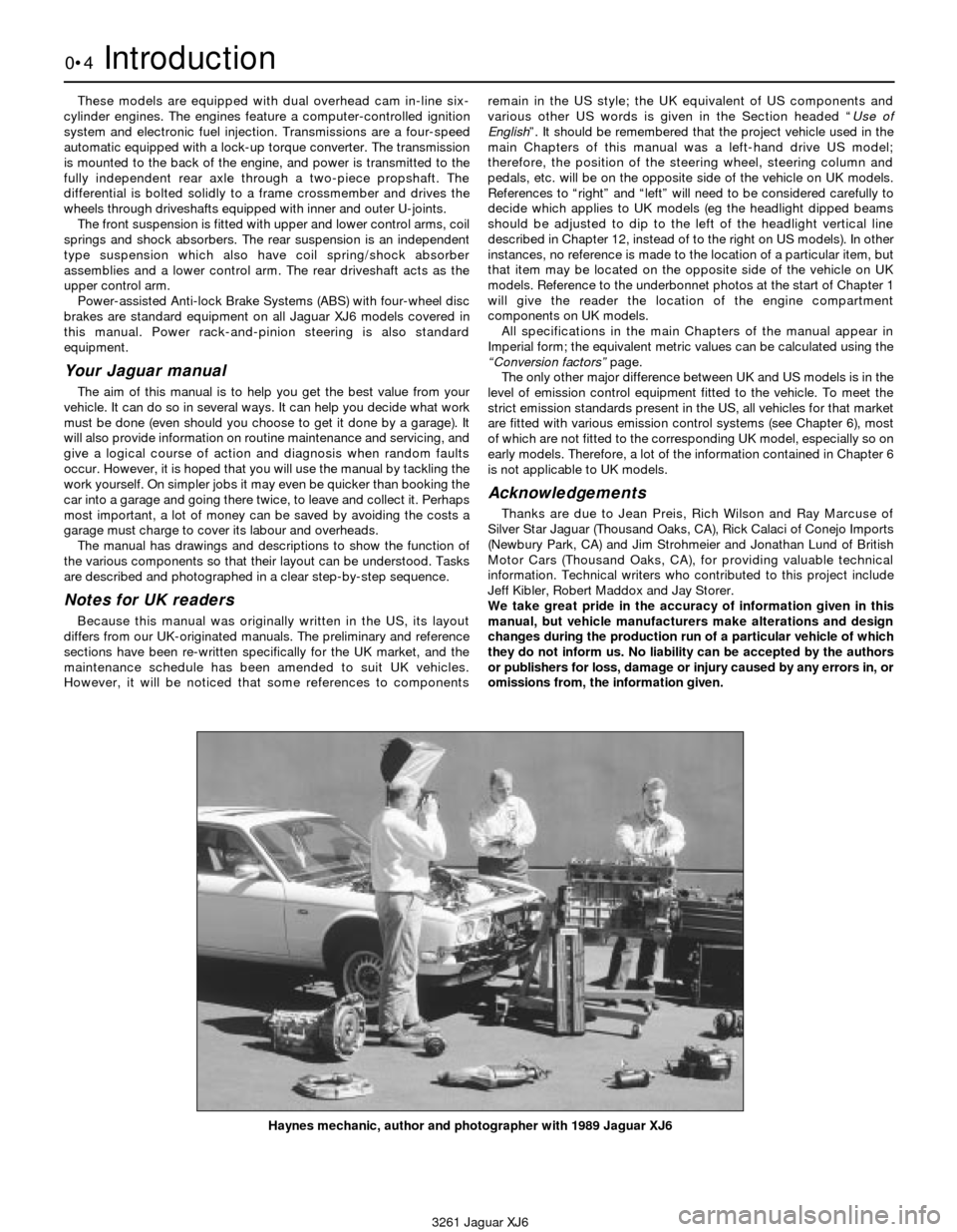
Haynes mechanic, author and photographer with 1989 Jaguar XJ6
Page 6 of 227
3261 Jaguar XJ6
0•6Roadside repairs
The following pages are intended to help in dealing with
common roadside emergencies and breakdowns. You will find
more detailed fault finding information at the back of the
manual, and repair information in the main chapters.
If your car won’t start
and the starter motor
doesn’t turn
MIf it’s a model with automatic transmission, make sure the
selector is in ‘P’ or ‘N’.
MOpen the bonnet and make sure that the battery terminals
are clean and tight.
MSwitch on the headlights and try to start the engine. If the
headlights go very dim when you’re trying to start, the
battery is probably flat. Get out of trouble by jump starting
(see next page) using a friend’s car.
If your car won’t start
even though the starter
motor turns as normal
MIs there fuel in the tank?
MIs there moisture on electrical components under the
bonnet? Switch off the ignition, then wipe off any obvious
dampness with a dry cloth. Spray a water-repellent aerosol
product (WD-40 or equivalent) on ignition and fuel system
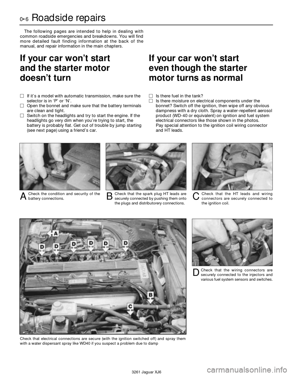
electrical connectors like those shown in the photos.
Pay special attention to the ignition coil wiring connector
and HT leads.
Check the condition and security of the
battery connections.ACheck that the spark plug HT leads are
securely connected by pushing them onto
the plugs and distributorery connections.BCheck that the HT leads and wiring
connectors are securely connected to
the ignition coil.C
Check that the wiring connectors are
securely connected to the injectors and
various fuel system sensors and switches.D
Check that electrical connections are secure (with the ignition switched off) and spray them
with a water dispersant spray like WD40 if you suspect a problem due to damp
Page 15 of 227
3261 Jaguar XJ6
Weekly checks0•15
Battery
Caution:Before carrying out any work on the
vehicle battery, read the precautions given in
"Safety first" at the start of this manual.
4Make sure that the battery tray is in good
condition, and that the clamp is tight.
Corrosion on the tray, retaining clamp and the
battery itself can be removed with a solution
of water and baking soda. Thoroughly rinse all
cleaned areas with water. Any metal parts
damaged by corrosion should be covered
with a zinc-based primer, then painted.
4Periodically (approximately every three
months), check the charge condition of the
battery as described in Chapter 5.
4If the battery is flat, and you need to jump
start your vehicle, see Roadside Repairs.
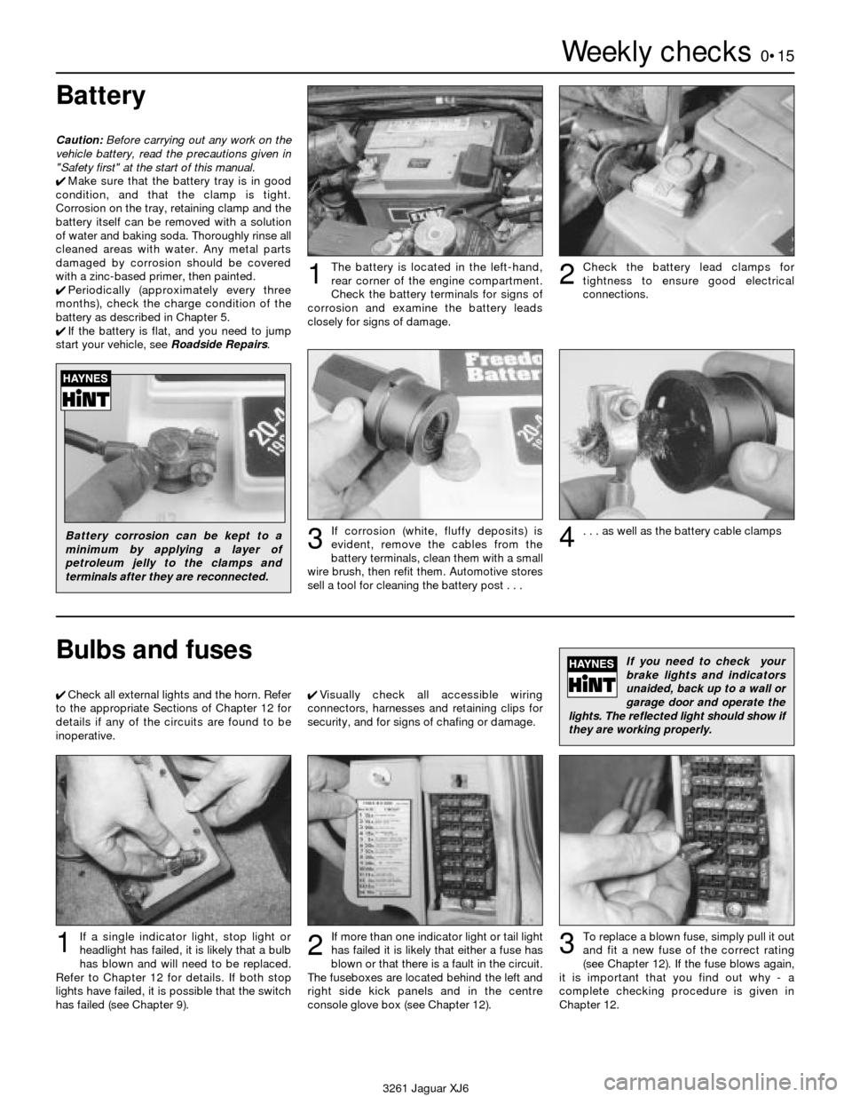
The battery is located in the left-hand,
rear corner of the engine compartment.
Check the battery terminals for signs of
corrosion and examine the battery leads
closely for signs of damage.1Check the battery lead clamps for
tightness to ensure good electrical
connections.2
Battery corrosion can be kept to a
minimum by applying a layer of
petroleum jelly to the clamps and
terminals after they are reconnected.If corrosion (white, fluffy deposits) is
evident, remove the cables from the
battery terminals, clean them with a small
wire brush, then refit them. Automotive stores
sell a tool for cleaning the battery post . . .3. . . as well as the battery cable clamps4
Bulbs and fuses
4Check all external lights and the horn. Refer
to the appropriate Sections of Chapter 12 for
details if any of the circuits are found to be
inoperative.4Visually check all accessible wiring
connectors, harnesses and retaining clips for
security, and for signs of chafing or damage.
If you need to check your
brake lights and indicators
unaided, back up to a wall or
garage door and operate the
lights. The reflected light should show if
they are working properly.
If a single indicator light, stop light or
headlight has failed, it is likely that a bulb
has blown and will need to be replaced.
Refer to Chapter 12 for details. If both stop
lights have failed, it is possible that the switch
has failed (see Chapter 9).If more than one indicator light or tail light
has failed it is likely that either a fuse has
blown or that there is a fault in the circuit.
The fuseboxes are located behind the left and
right side kick panels and in the centre
console glove box (see Chapter 12).
2
To replace a blown fuse, simply pull it out
and fit a new fuse of the correct rating
(see Chapter 12). If the fuse blows again,
it is important that you find out why - a
complete checking procedure is given in
Chapter 12.31
Page 17 of 227
3261 Jaguar XJ6
1
Chapter 1
Routine maintenance and servicing
Air cleaner element renewal . . . . . . . . . . . . . . . . . . . . . . . . . . . . . . . . 17
Automatic transmission fluid and filter renewal . . . . . . . . . . . . . . . . . 26
Automatic transmission fluid level check . . . . . . . . . . . . . . . . . . . . . 8
Battery check and general information . . . . . . . . . . . . . . . . . . . . . . . 6
Brake fluid renewal . . . . . . . . . . . . . . . . . . . . . . . . . . . . . . . . . . . . . . 28
Braking system - general check and adjustment . . . . . . . . . . . . . . . 11
Coolant renewal . . . . . . . . . . . . . . . . . . . . . . . . . . . . . . . . . . . . . . . . . 30
Crankcase ventilation system check . . . . . . . . . . . . . . . . . . . . . . . . . 20
Differential oil level check . . . . . . . . . . . . . . . . . . . . . . . . . . . . . . . . . 9
Differential oil renewal . . . . . . . . . . . . . . . . . . . . . . . . . . . . . . . . . . . . 27
Drivebelt check and renewal . . . . . . . . . . . . . . . . . . . . . . . . . . . . . . . 21
Engine oil and filter renewal . . . . . . . . . . . . . . . . . . . . . . . . . . . . . . . . 3
Exhaust system check . . . . . . . . . . . . . . . . . . . . . . . . . . . . . . . . . . . . 10
Front wheel alignment check . . . . . . . . . . . . . . . . . . . . . . . . . . . . . . . 24
Front wheel bearing check and adjustment . . . . . . . . . . . . . . . . . . . 22Fuel filter renewal . . . . . . . . . . . . . . . . . . . . . . . . . . . . . . . . . . . . . . . . 18
General information . . . . . . . . . . . . . . . . . . . . . . . . . . . . . . . . . . . . . . 1
General lubrication . . . . . . . . . . . . . . . . . . . . . . . . . . . . . . . . . . . . . . . 14
Handbrake shoes check . . . . . . . . . . . . . . . . . . . . . . . . . . . . . . . . . . 29
Headlight beam check . . . . . . . . . . . . . . . . . . . . . . . . . . . . . . . . . . . . 25
Hose and fluid leak check . . . . . . . . . . . . . . . . . . . . . . . . . . . . . . . . . 7
Ignition system check . . . . . . . . . . . . . . . . . . . . . . . . . . . . . . . . . . . . 19
Intensive maintenance . . . . . . . . . . . . . . . . . . . . . . . . . . . . . . . . . . . . 2
Power hydraulic system fluid level check . . . . . . . . . . . . . . . . . . . . . 5
Propshaft check . . . . . . . . . . . . . . . . . . . . . . . . . . . . . . . . . . . . . . . . . 23
Road test . . . . . . . . . . . . . . . . . . . . . . . . . . . . . . . . . . . . . . . . . . . . . . 15
Seat belt check . . . . . . . . . . . . . . . . . . . . . . . . . . . . . . . . . . . . . . . . . 13
Spark plug check . . . . . . . . . . . . . . . . . . . . . . . . . . . . . . . . . . . . . . . . 4
Spark plug renewal . . . . . . . . . . . . . . . . . . . . . . . . . . . . . . . . . . . . . . 16
Steering and suspension check . . . . . . . . . . . . . . . . . . . . . . . . . . . . 12
1•1
Contents
Easy,suitable for
novice with little
experienceFairly easy,suitable
for beginner with
some experienceFairly difficult,
suitable for competent
DIY mechanic
Difficult,suitable for
experienced DIY
mechanicVery difficult,
suitable for expert DIY
or professional
Degrees of difficulty
54321
Page 18 of 227
Lubricants and fluids
Refer to “Weekly checks”
Capacities
Engine oil
Including oil filter . . . . . . . . . . . . . . . . . . . . . . . . . . . . . . . . . . . . . . . . . . . 8.0 litres
Cooling system
All models (approximate):
From dry . . . . . . . . . . . . . . . . . . . . . . . . . . . . . . . . . . . . . . . . . . . . . . . 12.8 litres
Drain and refill . . . . . . . . . . . . . . . . . . . . . . . . . . . . . . . . . . . . . . . . . . . 9.2 litres
Transmission
Automatic transmission (approximate):
From dry:
3.2 litre model . . . . . . . . . . . . . . . . . . . . . . . . . . . . . . . . . . . . . . . . . 7.4 litres
3.6 and 4.0 litre models . . . . . . . . . . . . . . . . . . . . . . . . . . . . . . . . . 8.0 litres
Drain and refill . . . . . . . . . . . . . . . . . . . . . . . . . . . . . . . . . . . . . . . . . . . 3.0 litres
Differential
All models (approximate) . . . . . . . . . . . . . . . . . . . . . . . . . . . . . . . . . . . . 2.1 litres
Cooling system
Antifreeze mixture:
50% antifreeze . . . . . . . . . . . . . . . . . . . . . . . . . . . . . . . . . . . . . . . . . . Protection down to -37°C (5°F)
55% antifreeze . . . . . . . . . . . . . . . . . . . . . . . . . . . . . . . . . . . . . . . . . . Protection down to -45°C (-22°F)
Note:Refer to antifreeze manufacturer for latest recommendations.
Ignition system
Spark plugs:
Type:
3.2 litre model . . . . . . . . . . . . . . . . . . . . . . . . . . . . . . . . . . . . . . . . . RC12YCC
3.6 and 4.0 litre models . . . . . . . . . . . . . . . . . . . . . . . . . . . . . . . . . RC9YCC
Electrode gap . . . . . . . . . . . . . . . . . . . . . . . . . . . . . . . . . . . . . . . . . . . 0.9 mm
*The spark plug gap quoted is that recommended by Champion
for their specified plug listed above. If spark plugs of any other type
are to be fitted, refer to their manufacturer’s recommendations.
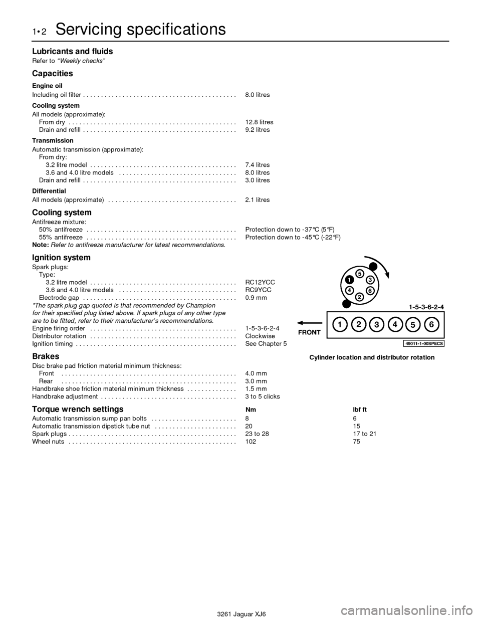
Engine firing order . . . . . . . . . . . . . . . . . . . . . . . . . . . . . . . . . . . . . . . . . 1-5-3-6-2-4
Distributor rotation . . . . . . . . . . . . . . . . . . . . . . . . . . . . . . . . . . . . . . . . . Clockwise
Ignition timing . . . . . . . . . . . . . . . . . . . . . . . . . . . . . . . . . . . . . . . . . . . . . See Chapter 5
Brakes
Disc brake pad friction material minimum thickness:
Front . . . . . . . . . . . . . . . . . . . . . . . . . . . . . . . . . . . . . . . . . . . . . . . . . 4.0 mm
Rear . . . . . . . . . . . . . . . . . . . . . . . . . . . . . . . . . . . . . . . . . . . . . . . . . 3.0 mm
Handbrake shoe friction material minimum thickness . . . . . . . . . . . . . . 1.5 mm
Handbrake adjustment . . . . . . . . . . . . . . . . . . . . . . . . . . . . . . . . . . . . . . 3 to 5 clicks
Torque wrench settingsNm lbf ft
Automatic transmission sump pan bolts . . . . . . . . . . . . . . . . . . . . . . . . 8 6
Automatic transmission dipstick tube nut . . . . . . . . . . . . . . . . . . . . . . . 20 15
Spark plugs . . . . . . . . . . . . . . . . . . . . . . . . . . . . . . . . . . . . . . . . . . . . . . . 23 to 28 17 to 21
Wheel nuts . . . . . . . . . . . . . . . . . . . . . . . . . . . . . . . . . . . . . . . . . . . . . . . 102 75
1•2Servicing specifications
3261 Jaguar XJ6
Cylinder location and distributor rotation
Page 22 of 227
1 General information
1This Chapter is designed to help the home
mechanic maintain his/her vehicle for safety,
economy, long life and peak performance.
2The Chapter contains a master
maintenance schedule, followed by Sections
dealing specifically with each task in the
schedule. Visual checks, adjustments,
component renewal and other helpful items
are included. Refer to the accompanying
illustrations of the engine compartment and
the underside of the vehicle for the locations
of the various components.
3Servicing your vehicle in accordance with
the mileage/time maintenance schedule and
the following Sections will provide a planned
maintenance programme, which should result
in a long and reliable service life. This is a
comprehensive plan, so maintaining some
items but not others at the specified service
intervals, will not produce the same results.
4As you service your vehicle, you will
discover that many of the procedures can -
and should - be grouped together, because of
the particular procedure being performed, or
because of the proximity of two otherwise-
unrelated components to one another. For
example, if the vehicle is raised for any
reason, the exhaust can be inspected at the
same time as the suspension and steering
components.
5The first step in this maintenance
programme is to prepare yourself before the
actual work begins. Read through all theSections relevant to the work to be carried out,
then make a list and gather all the parts and
tools required. If a problem is encountered,
seek advice from a parts specialist, or a dealer
service department.
2 Intensive maintenance
1If, from the time the vehicle is new, the
routine maintenance schedule is followed
closely, and frequent checks are made of fluid
levels and high-wear items, as suggested
throughout this manual, the engine will be
kept in relatively good running condition, and
the need for additional work will be minimised.
2It is possible that there will be times when
the engine is running poorly due to the lack of
regular maintenance. This is even more likely
if a used vehicle, which has not received
regular and frequent maintenance checks, is
purchased. In such cases, additional work
may need to be carried out, outside of the
regular maintenance intervals.
3If engine wear is suspected, a compression
test (refer to Chapter 2) will provide valuable
information regarding the overall performance
of the main internal components. Such a test
can be used as a basis to decide on the extent
of the work to be carried out. If, for example, a
compression test indicates serious internal
engine wear, conventional maintenance as
described in this Chapter will not greatly
improve the performance of the engine, and
may prove a waste of time and money, unless
extensive overhaul work is carried out first.4The following series of operations are those
which are most often required to improve the
performance of a generally poor-running
engine:
Primary operations
a) Clean, inspect and test the battery
(Section 6).
b) Check all the engine-related fluids (refer
to “Weekly checks”).
c) Check the condition and tension of the
auxiliary drivebelt (Section 21).
d) Renew the spark plugs (Section 16).
e) Inspect the distributor cap and rotor arm
(Section 19).
f) Check the condition of the air filter, and
renew if necessary (Section 17).
g) Renew the fuel filter (Section 18).
h) Check the condition of all hoses, and
check for fluid leaks (Section 7).
i) Check the exhaust gas emissions (see
Chapter 6).
5If the above operations do not prove fully
effective, carry out the following secondary
operations:
Secondary operations
All items listed under “Primary operations”,
plus the following:
a) Check the charging system (refer to
Chapter 5).
b) Check the ignition system (refer to
Chapter 5).
c) Check the fuel system (refer to Chapter 4).
d) Renew the distributor cap and rotor arm
(Section 19).
e) Renew the ignition HT leads (Section 19).
1•6Maintenance procedures
3261 Jaguar XJ6
Every 7500 miles (12 000 km) or 6 months
3 Engine oil and filter renewal
2
1Frequent oil changes are the best
preventive maintenance the home mechanic
can give the engine, because ageing oil
becomes diluted and contaminated, which
leads to premature engine wear.
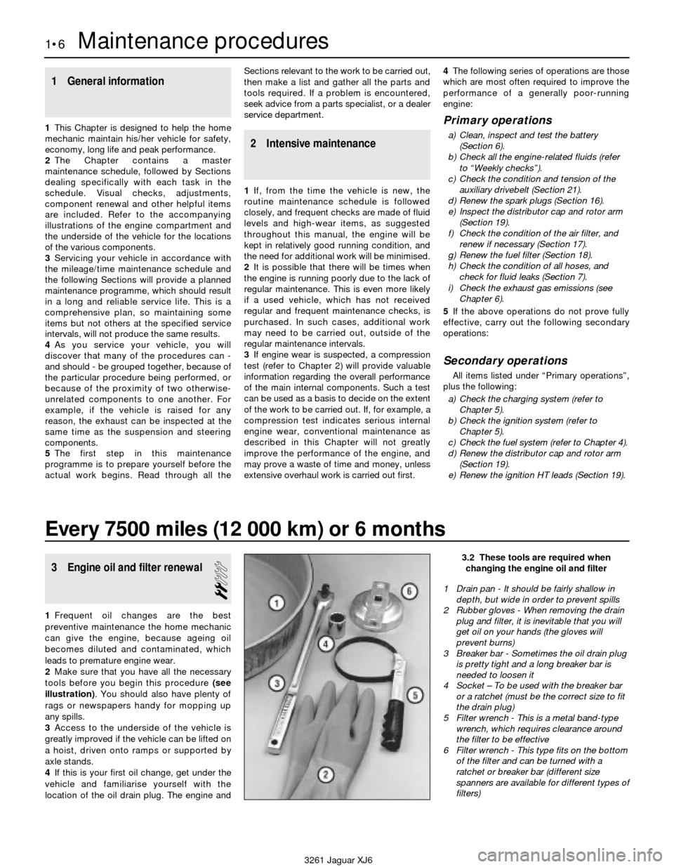
2Make sure that you have all the necessary
tools before you begin this procedure (see
illustration). You should also have plenty of
rags or newspapers handy for mopping up
any spills.
3Access to the underside of the vehicle is
greatly improved if the vehicle can be lifted on
a hoist, driven onto ramps or supported by
axle stands.
4If this is your first oil change, get under the
vehicle and familiarise yourself with the
location of the oil drain plug. The engine and
3.2 These tools are required when
changing the engine oil and filter
1 Drain pan - It should be fairly shallow in
depth, but wide in order to prevent spills
2 Rubber gloves - When removing the drain
plug and filter, it is inevitable that you will
get oil on your hands (the gloves will
prevent burns)
3 Breaker bar - Sometimes the oil drain plug
is pretty tight and a long breaker bar is
needed to loosen it
4 Socket – To be used with the breaker bar
or a ratchet (must be the correct size to fit
the drain plug)
5 Filter wrench - This is a metal band-type
wrench, which requires clearance around
the filter to be effective
6 Filter wrench - This type fits on the bottom
of the filter and can be turned with a
ratchet or breaker bar (different size
spanners are available for different types of
filters)
Page 23 of 227
exhaust components will be warm during the
actual work, so try to anticipate any potential
problems before the engine and accessories
are hot.
5Park the vehicle on a level spot. Start the
engine and allow it to reach its normal
operating temperature (the needle on the
temperature gauge should be at least above
the bottom mark). Warm oil and contaminates
will flow out more easily. Turn off the engine
when it’s warmed up. Remove the oil filler cap
located next to the valve cover.
6Raise the vehicle and support it on axle
stands.
Warning: To avoid personal
injury, never get beneath the
vehicle when it is supported by
only by a jack. The jack provided
with your vehicle is designed solely for
raising the vehicle to remove and replace
the wheels. Always use axle stands to
support the vehicle when it becomes
necessary to place your body underneath
the vehicle.
7Being careful not to touch the hot exhaust
components, place the drain pan under the
drain plug in the bottom of the pan and
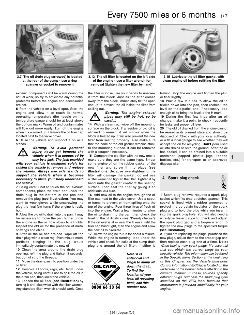
remove the plug (see illustration). You may
want to wear gloves while unscrewing the
plug the final few turns if the engine is really
hot.
8Allow the old oil to drain into the pan. It may
be necessary to move the pan farther under
the engine as the oil flow slows to a trickle.
Inspect the old oil for the presence of metal
shavings and chips.
9After all the oil has drained, wipe off the
drain plug with a clean rag. Even minute metal
particles clinging to the plug would
immediately contaminate the new oil.
10Clean the area around the drain plug
opening, refit the plug and tighten it securely,
but do not strip the threads.
11Move the drain pan into position under the
oil filter.
12Remove all tools, rags, etc. from under
the vehicle, being careful not to spill the oil in
the drain pan, then lower the vehicle.
13Loosen the oil filter (see illustration)by
turning it anti-clockwise with the filter wrench.
Any standard filter wrench should work. Oncethe filter is loose, use your hands to unscrew
it from the block. Just as the filter comes
away from the block, immediately tilt the open
end up to prevent the oil inside the filter from
spilling out.
Warning: The engine exhaust
pipes may still be hot, so be
careful.
14With a clean rag, wipe off the mounting
surface on the block. If a residue of old oil is
allowed to remain, it will smoke when the
block is heated up. It will also prevent the new
filter from seating properly. Also make sure
that the none of the old gasket remains stuck
to the mounting surface. It can be removed
with a scraper if necessary.
15Compare the old filter with the new one to
make sure they are the same type. Smear
some engine oil on the rubber gasket of the
new filter and screw it into place (see
illustration). Because over-tightening the
filter will damage the gasket, do not use
a filter wrench to tighten the filter. Tighten it by
hand until the gasket contacts the seating
surface. Then seat the filter by giving it an
additional 3/4-turn.
16Add new oil to the engine through the oil
filler cap next to the valve cover. Use a spout
or funnel to prevent oil from spilling onto the
top of the engine. Pour three litres of fresh oil
into the engine. Wait a few minutes to allow
the oil to drain into the pan, then check the
level on the oil dipstick (see “Weekly checks”).
If the oil level is at or near the H mark, refit the
filler cap hand tight, start the engine and allow
the new oil to circulate.
17Allow the engine to run for about a minute.
While the engine is running, look under the
vehicle and check for leaks at the sump drain
plug and around the oil filter. If either isleaking, stop the engine and tighten the plug
or filter slightly.
18Wait a few minutes to allow the oil to
trickle down into the pan, then recheck the
level on the dipstick and, if necessary, add
enough oil to bring the level to the H mark.
19During the first few trips after an oil
change, make it a point to check frequently
for leaks and proper oil level.
20The old oil drained from the engine cannot
be reused in its present state and should be
disposed of. Check with your local authority,
or with a local garage to see whether they will
accept the oil for recycling. Don’tpour used
oil into drains or onto the ground. After the oil
has cooled, it can be drained into a suitable
container (capped plastic jugs, topped
bottles, etc.) for transport to an approved
disposal site.
4 Spark plug check
2
1Spark plug renewal requires a spark plug
socket which fits onto a ratchet spanner. This
socket is lined with a rubber grommet to
protect the porcelain insulator of the spark
plug and to hold the plug while you insert it
into the spark plug hole. You will also need a
wire-type feeler gauge to check and adjust
the spark plug gap and a torque wrench to
tighten the new plugs to the specified torque
(see illustration).
2If you are replacing the plugs, purchase the
new plugs, adjust them to the proper gap and
then replace each plug one at a time. Note:
When buying new spark plugs, it’s essential
that you obtain the correct plugs for your
specific vehicle. This information can be found
in the Specifications Section at the beginning
of this Chapter, on the Vehicle Emissions
Control Information (VECI) label located on the
underside of the bonnet (where fitted)or in the
owner’s manual. If these sources specify
different plugs, purchase the spark plug type
specified on the VECI label because that
information is provided specifically for your
engine.
Every 7500 miles or 6 months 1•7
1
3.7 The oil drain plug (arrowed) is located
at the rear of the sump - use a ring
spanner or socket to remove it3.13 The oil filter is located on the left side
of the engine - use a filter wrench for
removal (tighten the new filter by hand)3.15 Lubricate the oil filter gasket with
clean engine oil before refitting the filter
3261 Jaguar XJ6
Note: It is
antisocial and
illegal to dump oil
down the drain.
To find the
location of your
local oil recycling
bank, call this
number free.
Page 24 of 227
3Inspect each of the new plugs for defects. If
there are any signs of cracks in the porcelain
insulator of a plug, don’t use it.
4Check the electrode gaps of the new plugs.
Check the gap by inserting the wire gauge of
the proper thickness between the electrodes
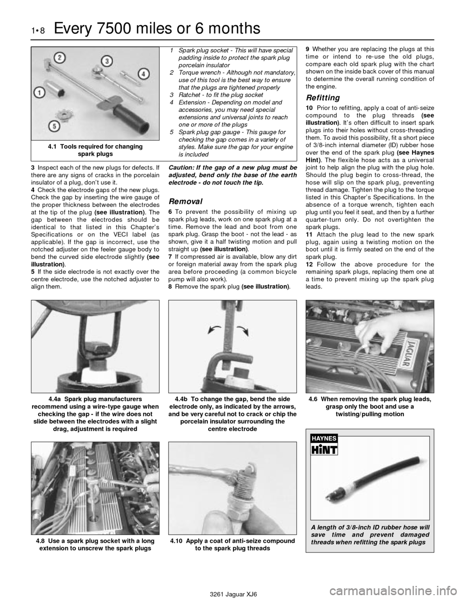
at the tip of the plug (see illustration). The
gap between the electrodes should be
identical to that listed in this Chapter’s
Specifications or on the VECI label (as
applicable). If the gap is incorrect, use the
notched adjuster on the feeler gauge body to
bend the curved side electrode slightly (see
illustration).
5If the side electrode is not exactly over the
centre electrode, use the notched adjuster to
align them.Caution: If the gap of a new plug must be
adjusted, bend only the base of the earth
electrode - do not touch the tip.
Removal
6To prevent the possibility of mixing up
spark plug leads, work on one spark plug at a
time. Remove the lead and boot from one
spark plug. Grasp the boot - not the lead - as
shown, give it a half twisting motion and pull
straight up (see illustration).
7If compressed air is available, blow any dirt
or foreign material away from the spark plug
area before proceeding (a common bicycle
pump will also work).
8Remove the spark plug (see illustration).9Whether you are replacing the plugs at this
time or intend to re-use the old plugs,
compare each old spark plug with the chart
shown on the inside back cover of this manual
to determine the overall running condition of
the engine.
Refitting
10Prior to refitting, apply a coat of anti-seize
compound to the plug threads (see
illustration). It’s often difficult to insert spark
plugs into their holes without cross-threading
them. To avoid this possibility, fit a short piece
of 3/8-inch internal diameter (ID) rubber hose
over the end of the spark plug (see Haynes
Hint). The flexible hose acts as a universal
joint to help align the plug with the plug hole.
Should the plug begin to cross-thread, the
hose will slip on the spark plug, preventing
thread damage. Tighten the plug to the torque
listed in this Chapter’s Specifications. In the
absence of a torque wrench, tighten each
plug until you feel it seat, and then by a further
quarter-turn only. Do not overtighten the
spark plugs.
11Attach the plug lead to the new spark
plug, again using a twisting motion on the
boot until it is firmly seated on the end of the
spark plug.
12Follow the above procedure for the
remaining spark plugs, replacing them one at
a time to prevent mixing up the spark plug
leads.
1•8Every 7500 miles or 6 months
4.4a Spark plug manufacturers
recommend using a wire-type gauge when
checking the gap - if the wire does not
slide between the electrodes with a slight
drag, adjustment is required4.4b To change the gap, bend the side
electrode only, as indicated by the arrows,
and be very careful not to crack or chip the
porcelain insulator surrounding the
centre electrode4.6 When removing the spark plug leads,
grasp only the boot and use a
twisting/pulling motion
4.8 Use a spark plug socket with a long
extension to unscrew the spark plugs
3261 Jaguar XJ6
4.1 Tools required for changing
spark plugs
1 Spark plug socket - This will have special
padding inside to protect the spark plug
porcelain insulator
2 Torque wrench - Although not mandatory,
use of this tool is the best way to ensure
that the plugs are tightened properly
3 Ratchet - to fit the plug socket
4 Extension - Depending on model and
accessories, you may need special
extensions and universal joints to reach
one or more of the plugs
5 Spark plug gap gauge - This gauge for
checking the gap comes in a variety of
styles. Make sure the gap for your engine
is included
4.10 Apply a coat of anti-seize compound
to the spark plug threads
A length of 3/8-inch ID rubber hose will
save time and prevent damaged
threads when refitting the spark plugs
Page 26 of 227
never ingest it. Wear protective safety glasses
when working near the battery. Keep children
away from the battery.
5Note the external condition of the battery. If
the positive terminal and cable clamp on your
vehicle’s battery is equipped with a rubber
protector, make sure it isn’t torn or damaged.
It should completely cover the terminal. Look
for any corroded or loose connections, cracks
in the case or cover or loose hold-down
clamps. Also check the entire length of each
cable for cracks and frayed conductors.
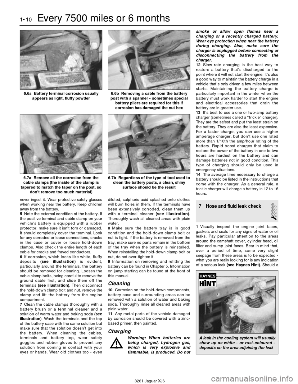
6If corrosion, which looks like white, fluffy
deposits (see illustration)is evident,
particularly around the terminals, the battery
should be removed for cleaning. Loosen the
cable clamp bolts, being careful to remove the
ground cable first, and slide them off the
terminals (see illustration). Then disconnect
the hold-down clamp bolt and nut, remove the
clamp and lift the battery from the engine
compartment.
7Clean the cable clamps thoroughly with a
battery brush or a terminal cleaner and a
solution of warm water and baking soda (see
illustration). Wash the terminals and the top
of the battery case with the same solution but
make sure that the solution doesn’t get into
the battery. When cleaning the cables,
terminals and battery top, wear safety
goggles and rubber gloves to prevent any
solution from coming in contact with your
eyes or hands. Wear old clothes too - evendiluted, sulphuric acid splashed onto clothes
will burn holes in them. If the terminals have
been extensively corroded, clean them up
with a terminal cleaner (see illustration).
Thoroughly wash all cleaned areas with plain
water.
8Make sure the battery tray is in good
condition and the hold-down clamp bolt or
nut is tight. If the battery is removed from the
tray, make sure no parts remain in the bottom
of the tray when the battery is reinstalled.
When reinstalling the hold-down clamp bolt or
nut, do not over-tighten it.
9Information on removing and refitting the
battery can be found in Chapter 5. Information
on jump starting can be found at the front of
this manual.
Cleaning
10Corrosion on the hold-down components,
battery case and surrounding areas can be
removed with a solution of water and baking
soda. Thoroughly rinse all cleaned areas with
plain water.
11Any metal parts of the vehicle damaged
by corrosion should be covered with a zinc-
based primer, then painted.
Charging
Warning: When batteries are
being charged, hydrogen gas,
which is very explosive and
flammable, is produced. Do notsmoke or allow open flames near a
charging or a recently charged battery.
Wear eye protection when near the battery
during charging. Also, make sure the
charger is unplugged before connecting or
disconnecting the battery from the
charger.
12Slow-rate charging is the best way to
restore a battery that’s discharged to the
point where it will not start the engine. It’s also
a good way to maintain the battery charge in a
vehicle that’s only driven a few miles between
starts. Maintaining the battery charge is
particularly important in the winter when the
battery must work harder to start the engine
and electrical accessories that drain the
battery are in greater use.
13It’s best to use a one or two-amp battery
charger (sometimes called a “trickle” charger).
They are the safest and put the least strain on
the battery. They are also the least expensive.
For a faster charge, you can use a higher
amperage charger, but don’t use one rated
more than 1/10th the amp/hour rating of the
battery. Rapid boost charges that claim to
restore the power of the battery in one to two
hours are hardest on the battery and can
damage batteries not in good condition. This
type of charging should only be used in
emergency situations.
14The average time necessary to charge a
battery should be listed in the instructions that
come with the charger. As a general rule, a
trickle charger will charge a battery in 12 to 16
hours.
7 Hose and fluid leak check
1
1Visually inspect the engine joint faces,
gaskets and seals for any signs of water or oil
leaks. Pay particular attention to the areas
around the camshaft cover, cylinder head, oil
filter and sump joint faces. Bear in mind that,
over a period of time, some very slight
seepage from these areas is to be expected -
what you are really looking for is any indication
of a serious leak (see Haynes Hint). Should a
1•10Every 7500 miles or 6 months
6.6a Battery terminal corrosion usually
appears as light, fluffy powder6.6b Removing a cable from the battery
post with a spanner - sometimes special
battery pliers are required for this if
corrosion has damaged the nut hex
6.7a Remove all the corrosion from the
cable clamps (the inside of the clamp is
tapered to match the taper on the post, so
don’t remove too much material)6.7b Regardless of the type of tool used to
clean the battery posts, a clean, shiny
surface should be the result
3261 Jaguar XJ6
A leak in the cooling system will usually
show up as white - or rust-coloured -
deposits on the area adjoining the leak
Page 27 of 227
leak be found, renew the offending gasket or
oil seal by referring to the appropriate
Chapters in this manual.
2Also check the security and condition of all
the engine-related pipes and hoses. Ensure
that all cable ties or securing clips are in place
and in good condition. Clips which are broken
or missing can lead to chafing of the hoses,
pipes or wiring, which could cause more
serious problems in the future.
3Carefully check the radiator hoses and
heater hoses along their entire length. Renew
any hose which is cracked, swollen or
deteriorated. Cracks will show up better if
the hose is squeezed. Pay close attention
to the hose clips that secure the hoses to the
cooling system components. Hose clips can
pinch and puncture hoses, resulting in cooling
system leaks.
4Inspect all the cooling system components
(hoses, joint faces etc.) for leaks. A leak in the
cooling system will usually show up as white-
or rust-coloured deposits on the area
adjoining the leak. Where any problems of this
nature are found on system components,
renew the component or gasket with
reference to Chapter 3.
5From within the engine compartment,
check the security of all fuel hose attachments
and pipe unions, and inspect the fuel hoses
and vacuum hoses for kinks, chafing and
deterioration.
6Also check the condition of the power
steering fluid hoses and pipes.
8 Automatic transmission
fluid level check
1
1The level of the automatic transmission fluid
should be carefully maintained. Low fluid level
can lead to slipping or loss of drive, while
overfilling can cause foaming, loss of fluid and
transmission damage.
2The transmission fluid level should only be
checked when the transmission is at its
normal operating temperature.
Caution: If the vehicle has just been driven
for a long time at high speed or in city
traffic in hot weather, or if it has been
pulling a trailer, an accurate fluid level
reading cannot be obtained. Allow the fluid
to cool down for about 30 minutes.
3If the vehicle has not been driven, park the
vehicle on level ground, set the handbrake,
then start the engine and bring it to operating
temperature. While the engine is idling,
depress the brake pedal and move the
selector lever through all the gear ranges,
beginning and ending in Park.
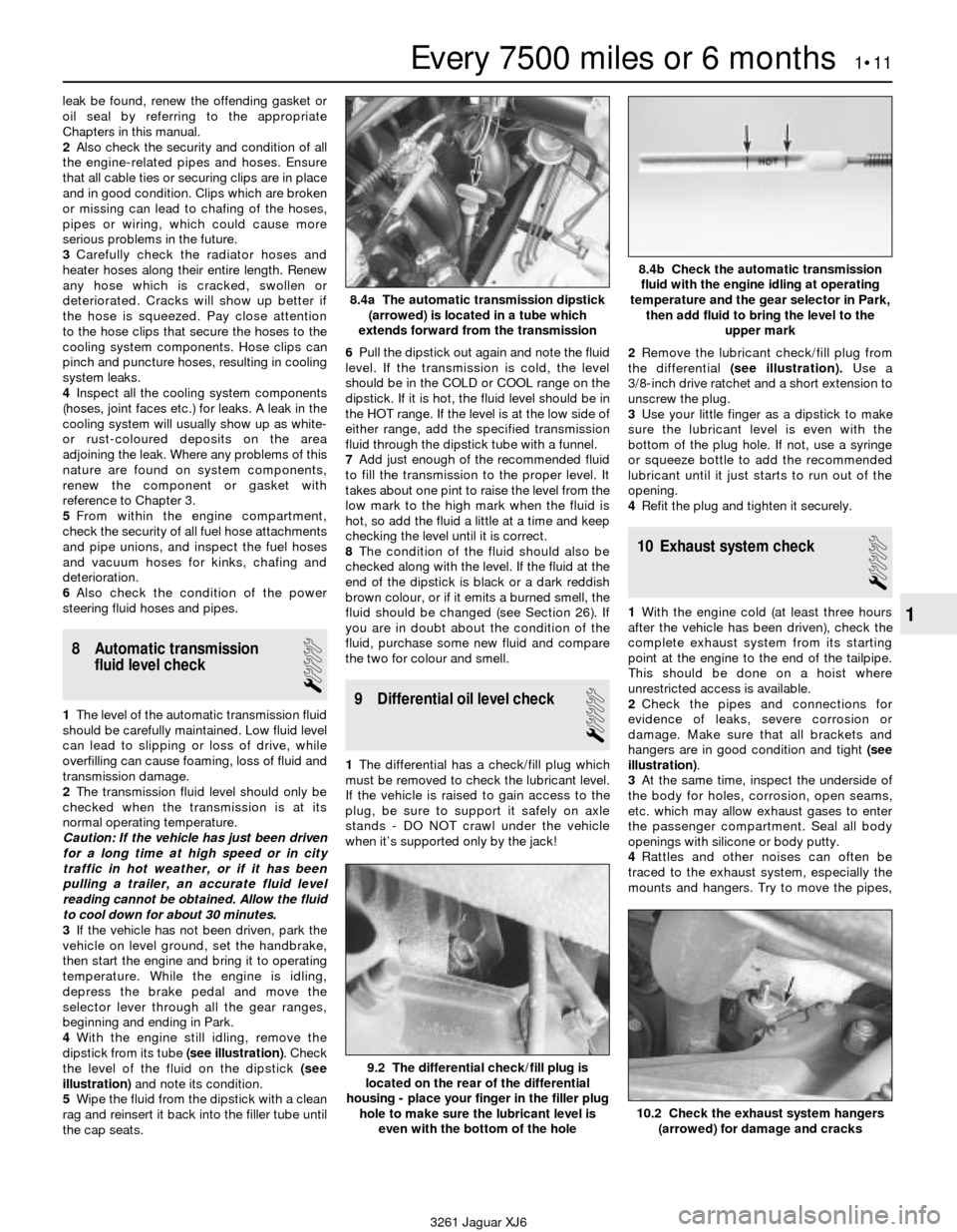
4With the engine still idling, remove the
dipstick from its tube (see illustration). Check
the level of the fluid on the dipstick (see
illustration)and note its condition.
5Wipe the fluid from the dipstick with a clean
rag and reinsert it back into the filler tube until
the cap seats.6Pull the dipstick out again and note the fluid
level. If the transmission is cold, the level
should be in the COLD or COOL range on the
dipstick. If it is hot, the fluid level should be in
the HOT range. If the level is at the low side of
either range, add the specified transmission
fluid through the dipstick tube with a funnel.
7Add just enough of the recommended fluid
to fill the transmission to the proper level. It
takes about one pint to raise the level from the
low mark to the high mark when the fluid is
hot, so add the fluid a little at a time and keep
checking the level until it is correct.
8The condition of the fluid should also be
checked along with the level. If the fluid at the
end of the dipstick is black or a dark reddish
brown colour, or if it emits a burned smell, the
fluid should be changed (see Section 26). If
you are in doubt about the condition of the
fluid, purchase some new fluid and compare
the two for colour and smell.9 Differential oil level check
1
1The differential has a check/fill plug which
must be removed to check the lubricant level.
If the vehicle is raised to gain access to the
plug, be sure to support it safely on axle
stands - DO NOT crawl under the vehicle
when it’s supported only by the jack!2Remove the lubricant check/fill plug from
the differential (see illustration).Use a
3/8-inch drive ratchet and a short extension to
unscrew the plug.
3Use your little finger as a dipstick to make
sure the lubricant level is even with the
bottom of the plug hole. If not, use a syringe
or squeeze bottle to add the recommended
lubricant until it just starts to run out of the
opening.
4Refit the plug and tighten it securely.
10 Exhaust system check
1
1With the engine cold (at least three hours
after the vehicle has been driven), check the
complete exhaust system from its starting
point at the engine to the end of the tailpipe.
This should be done on a hoist where
unrestricted access is available.
2Check the pipes and connections for
evidence of leaks, severe corrosion or
damage. Make sure that all brackets and
hangers are in good condition and tight (see
illustration).
3At the same time, inspect the underside of
the body for holes, corrosion, open seams,
etc. which may allow exhaust gases to enter
the passenger compartment. Seal all body
openings with silicone or body putty.
4Rattles and other noises can often be
traced to the exhaust system, especially the
mounts and hangers. Try to move the pipes,
Every 7500 miles or 6 months 1•11
1
9.2 The differential check/fill plug is
located on the rear of the differential
housing - place your finger in the filler plug
hole to make sure the lubricant level is
even with the bottom of the hole
10.2 Check the exhaust system hangers
(arrowed) for damage and cracks
3261 Jaguar XJ6
8.4a The automatic transmission dipstick
(arrowed) is located in a tube which
extends forward from the transmission
8.4b Check the automatic transmission
fluid with the engine idling at operating
temperature and the gear selector in Park,
then add fluid to bring the level to the
upper mark