Suspension and steering systems JAGUAR XJ6 1997 2.G Workshop Manual
[x] Cancel search | Manufacturer: JAGUAR, Model Year: 1997, Model line: XJ6, Model: JAGUAR XJ6 1997 2.GPages: 227, PDF Size: 7.2 MB
Page 3 of 227

3261 Jaguar XJ6
REPAIRS & OVERHAUL
Engine and associated systems
Engine in-car repair procedures Page 2A•1
Engine removal and overhaul procedures Page 2B•1
Cooling, heating and air conditioning systems Page 3•1
Fuel and exhaust systems Page 4•1
Engine electrical systems Page 5•1
Emissions and engine cone control systems Page 6•1
Transmission
Automatic transmissionPage 7•1
DrivetrainPage 8•1
Brakes and suspension
Braking systemPage 9•1
Suspension and steering systems Page 10•1
Body equipment
Bodywork and fittingsPage 11•1
Body electrical systems Page 12•1
Wiring diagramsPage 12•16
REFERENCE
Dimensions and weights Page REF•1
Jacking and vehicle support Page REF•1
Radio/cassette unit anti-theft system - precaution Page REF•1
Conversion factorsPage REF•2
Use of EnglishPage REF•3
Buying spare parts and vehicle identification Page REF•4
General repair procedures Page REF•5
Tools and working facilities Page REF•6
MOT test checksPage REF•8
Fault findingPage REF•12
Glossary of technical terms Page REF•18
IndexPage REF•22
Contents
Page 4 of 227
These models are equipped with dual overhead cam in-line six-
cylinder engines. The engines feature a computer-controlled ignition
system and electronic fuel injection. Transmissions are a four-speed
automatic equipped with a lock-up torque converter. The transmission
is mounted to the back of the engine, and power is transmitted to the
fully independent rear axle through a two-piece propshaft. The
differential is bolted solidly to a frame crossmember and drives the
wheels through driveshafts equipped with inner and outer U-joints.
The front suspension is fitted with upper and lower control arms, coil
springs and shock absorbers. The rear suspension is an independent
type suspension which also have coil spring/shock absorber
assemblies and a lower control arm. The rear driveshaft acts as the
upper control arm.
Power-assisted Anti-lock Brake Systems (ABS) with four-wheel disc
brakes are standard equipment on all Jaguar XJ6 models covered in
this manual. Power rack-and-pinion steering is also standard
equipment.
Your Jaguar manual
The aim of this manual is to help you get the best value from your
vehicle. It can do so in several ways. It can help you decide what work
must be done (even should you choose to get it done by a garage). It
will also provide information on routine maintenance and servicing, and
give a logical course of action and diagnosis when random faults
occur. However, it is hoped that you will use the manual by tackling the
work yourself. On simpler jobs it may even be quicker than booking the
car into a garage and going there twice, to leave and collect it. Perhaps
most important, a lot of money can be saved by avoiding the costs a
garage must charge to cover its labour and overheads.
The manual has drawings and descriptions to show the function of
the various components so that their layout can be understood. Tasks
are described and photographed in a clear step-by-step sequence.
Notes for UK readers
Because this manual was originally written in the US, its layout
differs from our UK-originated manuals. The preliminary and reference
sections have been re-written specifically for the UK market, and the
maintenance schedule has been amended to suit UK vehicles.
However, it will be noticed that some references to componentsremain in the US style; the UK equivalent of US components and
various other US words is given in the Section headed “Use of
English”. It should be remembered that the project vehicle used in the
main Chapters of this manual was a left-hand drive US model;
therefore, the position of the steering wheel, steering column and
pedals, etc. will be on the opposite side of the vehicle on UK models.
References to “right” and “left” will need to be considered carefully to
decide which applies to UK models (eg the headlight dipped beams
should be adjusted to dip to the left of the headlight vertical line
described in Chapter 12, instead of to the right on US models). In other
instances, no reference is made to the location of a particular item, but
that item may be located on the opposite side of the vehicle on UK
models. Reference to the underbonnet photos at the start of Chapter 1
will give the reader the location of the engine compartment
components on UK models.
All specifications in the main Chapters of the manual appear in
Imperial form; the equivalent metric values can be calculated using the
“Conversion factors”page.
The only other major difference between UK and US models is in the
level of emission control equipment fitted to the vehicle. To meet the
strict emission standards present in the US, all vehicles for that market
are fitted with various emission control systems (see Chapter 6), most
of which are not fitted to the corresponding UK model, especially so on
early models. Therefore, a lot of the information contained in Chapter 6
is not applicable to UK models.
Acknowledgements
Thanks are due to Jean Preis, Rich Wilson and Ray Marcuse of
Silver Star Jaguar (Thousand Oaks, CA), Rick Calaci of Conejo Imports
(Newbury Park, CA) and Jim Strohmeier and Jonathan Lund of British
Motor Cars (Thousand Oaks, CA), for providing valuable technical
information. Technical writers who contributed to this project include
Jeff Kibler, Robert Maddox and Jay Storer.
We take great pride in the accuracy of information given in this
manual, but vehicle manufacturers make alterations and design
changes during the production run of a particular vehicle of which
they do not inform us. No liability can be accepted by the authors
or publishers for loss, damage or injury caused by any errors in, or
omissions from, the information given.
0•4Introduction
3261 Jaguar XJ6
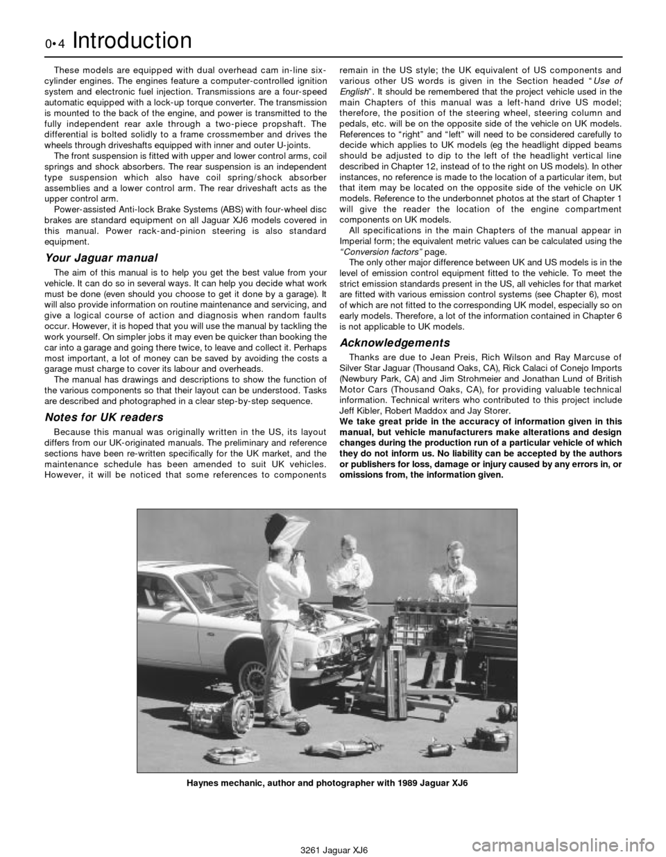
Haynes mechanic, author and photographer with 1989 Jaguar XJ6
Page 137 of 227
3261 Jaguar XJ6
10
Chapter 10
Suspension and steering systems
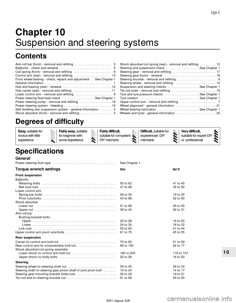
General
Power steering fluid type . . . . . . . . . . . . . . . . . . . . . . . . . . . . . . . . . . . . See Chapter 1
Torque wrench settingsNm lbf ft
Front suspension
Balljoints
Retaining bolts . . . . . . . . . . . . . . . . . . . . . . . . . . . . . . . . . . . . . . . . . . 55 to 62 41 to 45
Ball stud nuts . . . . . . . . . . . . . . . . . . . . . . . . . . . . . . . . . . . . . . . . . . . 47 to 68 35 to 50
Lower control arm
Spring pan bolts . . . . . . . . . . . . . . . . . . . . . . . . . . . . . . . . . . . . . . . . . 26 to 34 19 to 25
Pivot nuts/bolts . . . . . . . . . . . . . . . . . . . . . . . . . . . . . . . . . . . . . . . . . . 43 to 68 32 to 50
Shock absorber
Lower nut . . . . . . . . . . . . . . . . . . . . . . . . . . . . . . . . . . . . . . . . . . . . . . 61 to 68 45 to 50
Upper nut . . . . . . . . . . . . . . . . . . . . . . . . . . . . . . . . . . . . . . . . . . . . . . 35 to 43 26 to 31
Anti-roll bar
Bushing bracket bolts
Upper . . . . . . . . . . . . . . . . . . . . . . . . . . . . . . . . . . . . . . . . . . . . . . . 22 to 28 16 to 20
Lower . . . . . . . . . . . . . . . . . . . . . . . . . . . . . . . . . . . . . . . . . . . . . . . 24 to 30 18 to 22
Link nuts . . . . . . . . . . . . . . . . . . . . . . . . . . . . . . . . . . . . . . . . . . . . . . . 55 to 60 41 to 44
Upper control arm pivot nuts/bolts . . . . . . . . . . . . . . . . . . . . . . . . . . . . 61 to 75 45 to 55
Rear suspension
Carrier-to-control arm bolt/nut . . . . . . . . . . . . . . . . . . . . . . . . . . . . . . . . 70 to 80 51 to 59
Rear control arm-to-crossmember bolt/nut . . . . . . . . . . . . . . . . . . . . . . 85 to 105 62 to 77
Shock absorber/coil spring assembly
Lower shock-to-control arm bolt/nut . . . . . . . . . . . . . . . . . . . . . . . . . 160 to 200 118 to 147
Upper shock-to-body bolts . . . . . . . . . . . . . . . . . . . . . . . . . . . . . . . . 22 to 28 16 to 20
Steering
Steering wheel-to-steering shaft nut . . . . . . . . . . . . . . . . . . . . . . . . . . . 35 to 45 26 to 33
Steering shaft-to-steering gear pinion shaft U-joint pinch bolt . . . . . . . 19 to 24 14 to 17
Steering gear mounting bracket bolts/nuts . . . . . . . . . . . . . . . . . . . . . . 26 to 29 19 to 21
Tie-rod end-to-steering knuckle nut . . . . . . . . . . . . . . . . . . . . . . . . . . . . 61 to 68 45 to 50 Anti-roll bar (front) - removal and refitting . . . . . . . . . . . . . . . . . . . . . 3
Balljoints - check and renewal . . . . . . . . . . . . . . . . . . . . . . . . . . . . . . 5
Coil spring (front) - removal and refitting . . . . . . . . . . . . . . . . . . . . . . 8
Control arm (rear) - removal and refitting . . . . . . . . . . . . . . . . . . . . . 13
Front wheel bearing - check, repack and adjustment . . See Chapter 1
General information . . . . . . . . . . . . . . . . . . . . . . . . . . . . . . . . . . . . . . 1
Hub and bearing (rear) - renewal . . . . . . . . . . . . . . . . . . . . . . . . . . . . 12
Hub carrier (rear) - removal and refitting . . . . . . . . . . . . . . . . . . . . . . 11
Lower control arm - removal and refitting . . . . . . . . . . . . . . . . . . . . . 9
Power steering fluid level check . . . . . . . . . . . . . . . . . . . See Chapter 1
Power steering pump - removal and refitting . . . . . . . . . . . . . . . . . . 18
Power steering system - bleeding . . . . . . . . . . . . . . . . . . . . . . . . . . . 19
Self-levelling rear suspension system - general information . . . . . . . 2
Shock absorber (front) - removal and refitting . . . . . . . . . . . . . . . . . . 4Shock absorber/coil spring (rear) - removal and refitting . . . . . . . . . 10
Steering and suspension check . . . . . . . . . . . . . . . . . . . See Chapter 1
Steering gear - removal and refitting . . . . . . . . . . . . . . . . . . . . . . . . . 17
Steering gear boots - renewal . . . . . . . . . . . . . . . . . . . . . . . . . . . . . . 16
Steering knuckle - removal and refitting . . . . . . . . . . . . . . . . . . . . . . 6
Steering wheel - removal and refitting . . . . . . . . . . . . . . . . . . . . . . . . 14
Suspension and steering checks . . . . . . . . . . . . . . . . . . See Chapter 1
Tie-rod ends - removal and refitting . . . . . . . . . . . . . . . . . . . . . . . . . 15
Tyre and tyre pressure checks . . . . . . . . . . . . . . . . . . . . See Chapter 1
Tyre rotation . . . . . . . . . . . . . . . . . . . . . . . . . . . . . . . . . . See Chapter 1
Upper control arm - removal and refitting . . . . . . . . . . . . . . . . . . . . . 7
Wheel alignment - general information . . . . . . . . . . . . . . . . . . . . . . . 21
Wheel bearing lubrication . . . . . . . . . . . . . . . . . . . . . . . . See Chapter 1
Wheels and tyres - general information . . . . . . . . . . . . . . . . . . . . . . . 20
10•1
Specifications Contents
Easy,suitable for
novice with little
experienceFairly easy,suitable
for beginner with
some experienceFairly difficult,
suitable for competent
DIY mechanic
Difficult,suitable for
experienced DIY
mechanicVery difficult,
suitable for expert DIY
or professional
Degrees of difficulty
54321
Page 138 of 227

1.2 Front suspension (left corner)
1 Anti-roll bar bushing bracket
2 Anti-roll bar link
3 Anti-roll bar
4 Coil spring pan
5 Lower control arm
6 Coil spring
7 Upper control arm
8 Lower balljoint
9 Steering knuckle
10 Tie-rod end
11 Tie-rod
12 Steering gear boot
10•2 Suspension and steering systems
1.1 Front suspension and steering systems
1 Anti-roll bar
2 Anti-roll bar bushing brackets
3 Anti-roll bar links4 Lower control arms
5 Steering knuckles
6 Tie-rod ends7 Tie-rods
8 Steering gear boots
9 Steering gear10 Suspension crossmember
11 Lower control arm crossbrace
3261 Jaguar XJ6
Page 139 of 227
1 General information
Warning: Whenever any of the
suspension or steering fasteners
are loosened or removed, they
must be inspected and if
necessary, replaced with new ones of the
same part number or of original equipment
quality and design. Torque wrench settings
must be followed for proper reassembly
and component retention. Never attempt
to heat, straighten or weld any suspension
or steering component. Instead, renew any
bent or damaged part.
The front suspension (see illustrations)
consists of unequal-length upper and lower
control arms, shock absorbers and coil
springs. The upper ends of the shocks are
attached to the body; the lower ends
are attached to the lower control arms. The
upper ends of the coil springs are seated
against the suspension crossmember; the
lower ends are seated against removable
plates which are bolted to the lower control
arms. The steering knuckles are attached to
balljoints in the upper and lower control arms.
An anti-roll bar is attached to the suspension
crossmember with a pair of bushing brackets
and to the lower control arms via a connecting
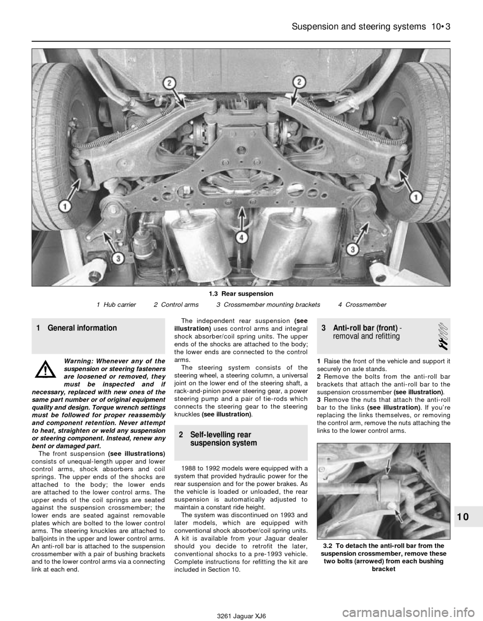
link at each end.The independent rear suspension (see
illustration)uses control arms and integral
shock absorber/coil spring units. The upper
ends of the shocks are attached to the body;
the lower ends are connected to the control
arms.
The steering system consists of the
steering wheel, a steering column, a universal
joint on the lower end of the steering shaft, a
rack-and-pinion power steering gear, a power
steering pump and a pair of tie-rods which
connects the steering gear to the steering
knuckles (see illustration).
2 Self-levelling rear
suspension system
1988 to 1992 models were equipped with a
system that provided hydraulic power for the
rear suspension and for the power brakes. As
the vehicle is loaded or unloaded, the rear
suspension is automatically adjusted to
maintain a constant ride height.
The system was discontinued on 1993 and
later models, which are equipped with
conventional shock absorber/coil spring units.
A kit is available from your Jaguar dealer
should you decide to retrofit the later,
conventional shocks to a pre-1993 vehicle.
Complete instructions for refitting the kit are
included in Section 10.
3 Anti-roll bar (front)-
removal and refitting
2
1Raise the front of the vehicle and support it
securely on axle stands.
2Remove the bolts from the anti-roll bar
brackets that attach the anti-roll bar to the
suspension crossmember (see illustration).
3Remove the nuts that attach the anti-roll
bar to the links (see illustration). If you’re
replacing the links themselves, or removing
the control arm, remove the nuts attaching the
links to the lower control arms.
Suspension and steering systems 10•3
10
1.3 Rear suspension
1 Hub carrier 2 Control arms 3 Crossmember mounting brackets 4 Crossmember
3.2 To detach the anti-roll bar from the
suspension crossmember, remove these
two bolts (arrowed) from each bushing
bracket
3261 Jaguar XJ6
Page 140 of 227
4Remove the anti-roll bar from the vehicle.
5Refitting is the reverse of the removal
procedure. Be sure to tighten all fasteners to
the torque listed in this Chapter’s
Specifications.
4 Shock absorber (front)-
removal and refitting
2
Note: Always renew both left and right shocks
at the same time to prevent handling
peculiarities and abnormal ride quality.
1Loosen but do not remove the front wheel
nuts. Raise the front of the vehicle and
support it on axle stands. Remove the wheels.
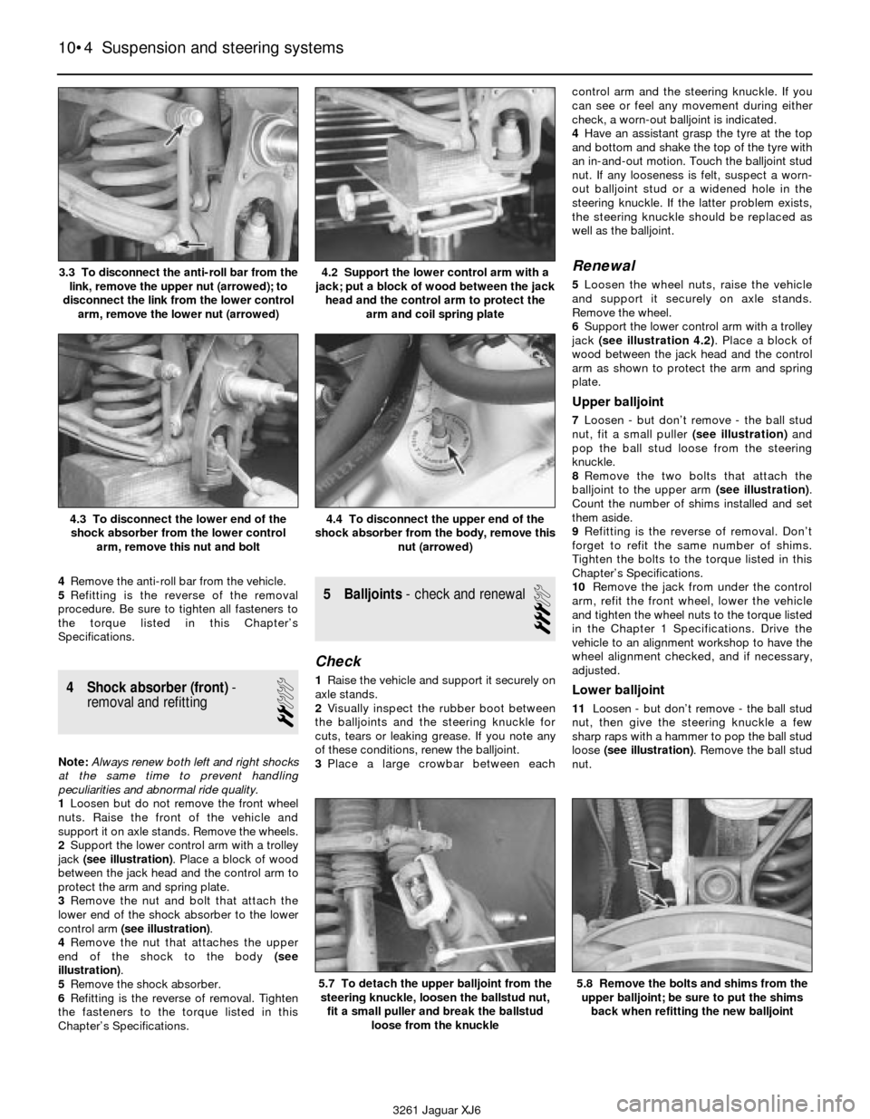
2Support the lower control arm with a trolley
jack (see illustration). Place a block of wood
between the jack head and the control arm to
protect the arm and spring plate.
3Remove the nut and bolt that attach the
lower end of the shock absorber to the lower
control arm (see illustration).
4Remove the nut that attaches the upper
end of the shock to the body (see
illustration).
5Remove the shock absorber.
6Refitting is the reverse of removal. Tighten
the fasteners to the torque listed in this
Chapter’s Specifications.
5 Balljoints- check and renewal
3
Check
1Raise the vehicle and support it securely on
axle stands.
2Visually inspect the rubber boot between
the balljoints and the steering knuckle for
cuts, tears or leaking grease. If you note any
of these conditions, renew the balljoint.
3Place a large crowbar between eachcontrol arm and the steering knuckle. If you
can see or feel any movement during either
check, a worn-out balljoint is indicated.
4Have an assistant grasp the tyre at the top
and bottom and shake the top of the tyre with
an in-and-out motion. Touch the balljoint stud
nut. If any looseness is felt, suspect a worn-
out balljoint stud or a widened hole in the
steering knuckle. If the latter problem exists,
the steering knuckle should be replaced as
well as the balljoint.
Renewal
5Loosen the wheel nuts, raise the vehicle
and support it securely on axle stands.
Remove the wheel.
6Support the lower control arm with a trolley
jack (see illustration 4.2). Place a block of
wood between the jack head and the control
arm as shown to protect the arm and spring
plate.
Upper balljoint
7Loosen - but don’t remove - the ball stud
nut, fit a small puller (see illustration)and
pop the ball stud loose from the steering
knuckle.
8Remove the two bolts that attach the
balljoint to the upper arm (see illustration).
Count the number of shims installed and set
them aside.
9Refitting is the reverse of removal. Don’t
forget to refit the same number of shims.
Tighten the bolts to the torque listed in this
Chapter’s Specifications.
10Remove the jack from under the control
arm, refit the front wheel, lower the vehicle
and tighten the wheel nuts to the torque listed
in the Chapter 1 Specifications. Drive the
vehicle to an alignment workshop to have the
wheel alignment checked, and if necessary,
adjusted.
Lower balljoint
11Loosen - but don’t remove - the ball stud
nut, then give the steering knuckle a few
sharp raps with a hammer to pop the ball stud
loose (see illustration). Remove the ball stud
nut.
10•4 Suspension and steering systems
3.3 To disconnect the anti-roll bar from the
link, remove the upper nut (arrowed); to
disconnect the link from the lower control
arm, remove the lower nut (arrowed)4.2 Support the lower control arm with a
jack; put a block of wood between the jack
head and the control arm to protect the
arm and coil spring plate
4.3 To disconnect the lower end of the
shock absorber from the lower control
arm, remove this nut and bolt4.4 To disconnect the upper end of the
shock absorber from the body, remove this
nut (arrowed)
5.7 To detach the upper balljoint from the
steering knuckle, loosen the ballstud nut,
fit a small puller and break the ballstud
loose from the knuckle5.8 Remove the bolts and shims from the
upper balljoint; be sure to put the shims
back when refitting the new balljoint
3261 Jaguar XJ6
Page 141 of 227
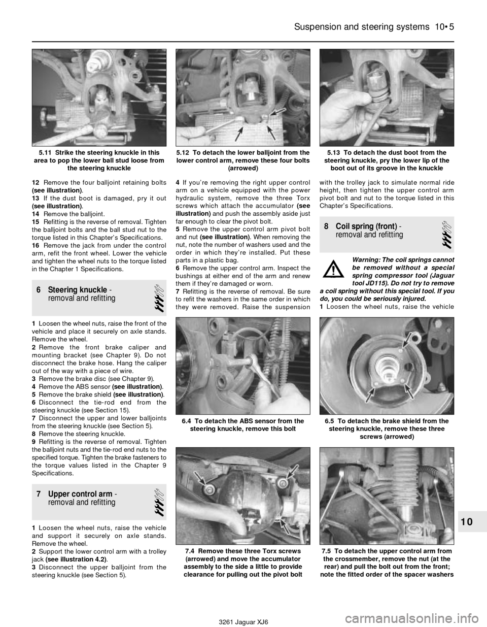
12Remove the four balljoint retaining bolts
(see illustration).
13If the dust boot is damaged, pry it out
(see illustration).
14Remove the balljoint.
15Refitting is the reverse of removal. Tighten
the balljoint bolts and the ball stud nut to the
torque listed in this Chapter’s Specifications.
16Remove the jack from under the control
arm, refit the front wheel. Lower the vehicle
and tighten the wheel nuts to the torque listed
in the Chapter 1 Specifications.
6 Steering knuckle-
removal and refitting
3
1Loosen the wheel nuts, raise the front of the
vehicle and place it securely on axle stands.
Remove the wheel.
2Remove the front brake caliper and
mounting bracket (see Chapter 9). Do not
disconnect the brake hose. Hang the caliper
out of the way with a piece of wire.
3Remove the brake disc (see Chapter 9).
4Remove the ABS sensor (see illustration).
5Remove the brake shield (see illustration).
6Disconnect the tie-rod end from the
steering knuckle (see Section 15).
7Disconnect the upper and lower balljoints
from the steering knuckle (see Section 5).
8Remove the steering knuckle.
9Refitting is the reverse of removal. Tighten
the balljoint nuts and the tie-rod end nuts to the
specified torque. Tighten the brake fasteners to
the torque values listed in the Chapter 9
Specifications.
7 Upper control arm-
removal and refitting
3
1Loosen the wheel nuts, raise the vehicle
and support it securely on axle stands.
Remove the wheel.
2Support the lower control arm with a trolley
jack (see illustration 4.2).
3Disconnect the upper balljoint from the
steering knuckle (see Section 5).4If you’re removing the right upper control
arm on a vehicle equipped with the power
hydraulic system, remove the three Torx
screws which attach the accumulator (see
illustration)and push the assembly aside just
far enough to clear the pivot bolt.
5Remove the upper control arm pivot bolt
and nut (see illustration). When removing the
nut, note the number of washers used and the
order in which they’re installed. Put these
parts in a plastic bag.
6Remove the upper control arm. Inspect the
bushings at either end of the arm and renew
them if they’re damaged or worn.
7Refitting is the reverse of removal. Be sure
to refit the washers in the same order in which
they were removed. Raise the suspensionwith the trolley jack to simulate normal ride
height, then tighten the upper control arm
pivot bolt and nut to the torque listed in this
Chapter’s Specifications.
8 Coil spring (front)-
removal and refitting
3
Warning: The coil springs cannot
be removed without a special
spring compressor tool (Jaguar
tool JD115). Do not try to remove
a coil spring without this special tool. If you
do, you could be seriously injured.
1Loosen the wheel nuts, raise the vehicle
Suspension and steering systems 10•5
10
5.11 Strike the steering knuckle in this
area to pop the lower ball stud loose from
the steering knuckle5.12 To detach the lower balljoint from the
lower control arm, remove these four bolts
(arrowed)5.13 To detach the dust boot from the
steering knuckle, pry the lower lip of the
boot out of its groove in the knuckle
6.5 To detach the brake shield from the
steering knuckle, remove these three
screws (arrowed)6.4 To detach the ABS sensor from the
steering knuckle, remove this bolt
7.4 Remove these three Torx screws
(arrowed) and move the accumulator
assembly to the side a little to provide
clearance for pulling out the pivot bolt7.5 To detach the upper control arm from
the crossmember, remove the nut (at the
rear) and pull the bolt out from the front;
note the fitted order of the spacer washers
3261 Jaguar XJ6
Page 142 of 227
and support it securely on axle stands.
Remove the wheel.
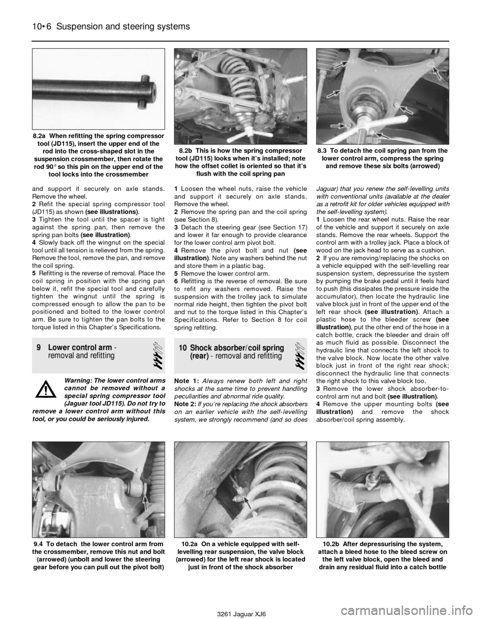
2Refit the special spring compressor tool
(JD115) as shown (see illustrations).
3Tighten the tool until the spacer is tight
against the spring pan, then remove the
spring pan bolts (see illustration).
4Slowly back off the wingnut on the special
tool until all tension is relieved from the spring.
Remove the tool, remove the pan, and remove
the coil spring.
5Refitting is the reverse of removal. Place the
coil spring in position with the spring pan
below it, refit the special tool and carefully
tighten the wingnut until the spring is
compressed enough to allow the pan to be
positioned and bolted to the lower control
arm. Be sure to tighten the pan bolts to the
torque listed in this Chapter’s Specifications.
9 Lower control arm-
removal and refitting
3
Warning: The lower control arms
cannot be removed without a
special spring compressor tool
(Jaguar tool JD115). Do not try to
remove a lower control arm without this
tool, or you could be seriously injured.1Loosen the wheel nuts, raise the vehicle
and support it securely on axle stands.
Remove the wheel.
2Remove the spring pan and the coil spring
(see Section 8).
3Detach the steering gear (see Section 17)
and lower it far enough to provide clearance
for the lower control arm pivot bolt.
4Remove the pivot bolt and nut (see
illustration). Note any washers behind the nut
and store them in a plastic bag.
5Remove the lower control arm.
6Refitting is the reverse of removal. Be sure
to refit any washers removed. Raise the
suspension with the trolley jack to simulate
normal ride height, then tighten the pivot bolt
and nut to the torque listed in this Chapter’s
Specifications. Refer to Section 8 for coil
spring refitting.
10 Shock absorber/coil spring
(rear)- removal and refitting
3
Note 1: Always renew both left and right
shocks at the same time to prevent handling
peculiarities and abnormal ride quality.
Note 2:If you’re replacing the shock absorbers
on an earlier vehicle with the self-levelling
system, we strongly recommend (and so doesJaguar) that you renew the self-levelling units
with conventional units (available at the dealer
as a retrofit kit for older vehicles equipped with
the self-levelling system).
1Loosen the rear wheel nuts. Raise the rear
of the vehicle and support it securely on axle
stands. Remove the rear wheels. Support the
control arm with a trolley jack. Place a block of
wood on the jack head to serve as a cushion.
2If you are removing/replacing the shocks on
a vehicle equipped with the self-levelling rear
suspension system, depressurise the system
by pumping the brake pedal until it feels hard
to push (this dissipates the pressure inside the
accumulator), then locate the hydraulic line
valve block just in front of the upper end of the
left rear shock (see illustration). Attach a
plastic hose to the bleeder screw (see
illustration), put the other end of the hose in a
catch bottle, crack the bleeder and drain off
as much fluid as possible. Disconnect the
hydraulic line that connects the left shock to
the valve block. Now locate the other valve
block just in front of the right rear shock;
disconnect the hydraulic line that connects
the right shock to this valve block too.
3Remove the lower shock absorber-to-
control arm nut and bolt (see illustration).
4Remove the upper mounting bolts (see
illustration)and remove the shock
absorber/coil spring assembly.
10•6 Suspension and steering systems
9.4 To detach the lower control arm from
the crossmember, remove this nut and bolt
(arrowed) (unbolt and lower the steering
gear before you can pull out the pivot bolt)10.2a On a vehicle equipped with self-
levelling rear suspension, the valve block
(arrowed) for the left rear shock is located
just in front of the shock absorber10.2b After depressurising the system,
attach a bleed hose to the bleed screw on
the left valve block, open the bleed and
drain any residual fluid into a catch bottle
3261 Jaguar XJ6 8.2a When refitting the spring compressor
tool (JD115), insert the upper end of the
rod into the cross-shaped slot in the
suspension crossmember, then rotate the
rod 90° so this pin on the upper end of the
tool locks into the crossmember
8.2b This is how the spring compressor
tool (JD115) looks when it’s installed; note
how the offset collet is oriented so that it’s
flush with the coil spring pan8.3 To detach the coil spring pan from the
lower control arm, compress the spring
and remove these six bolts (arrowed)
Page 143 of 227
5The shock/coil spring assemblies must be
dismantled, and the coil springs installed on
the new shocks. Although the shock/coil
spring assembly is similar in appearance to
the a MacPherson strut/coil spring assembly,
the spring on this unit is much stiffer.
Therefore, DO NOT attempt to take apart this
unit yourself with a strut spring compressor
tool. Instead, take the unit to a Jaguar dealer
service department or to a Jaguar specialist
workshop and have the springs installed on
the new shocks by professionals.6If you are retrofitting conventional shocks -
rather than refitting the same or another pair
of self-levelling shocks - unplug the electrical
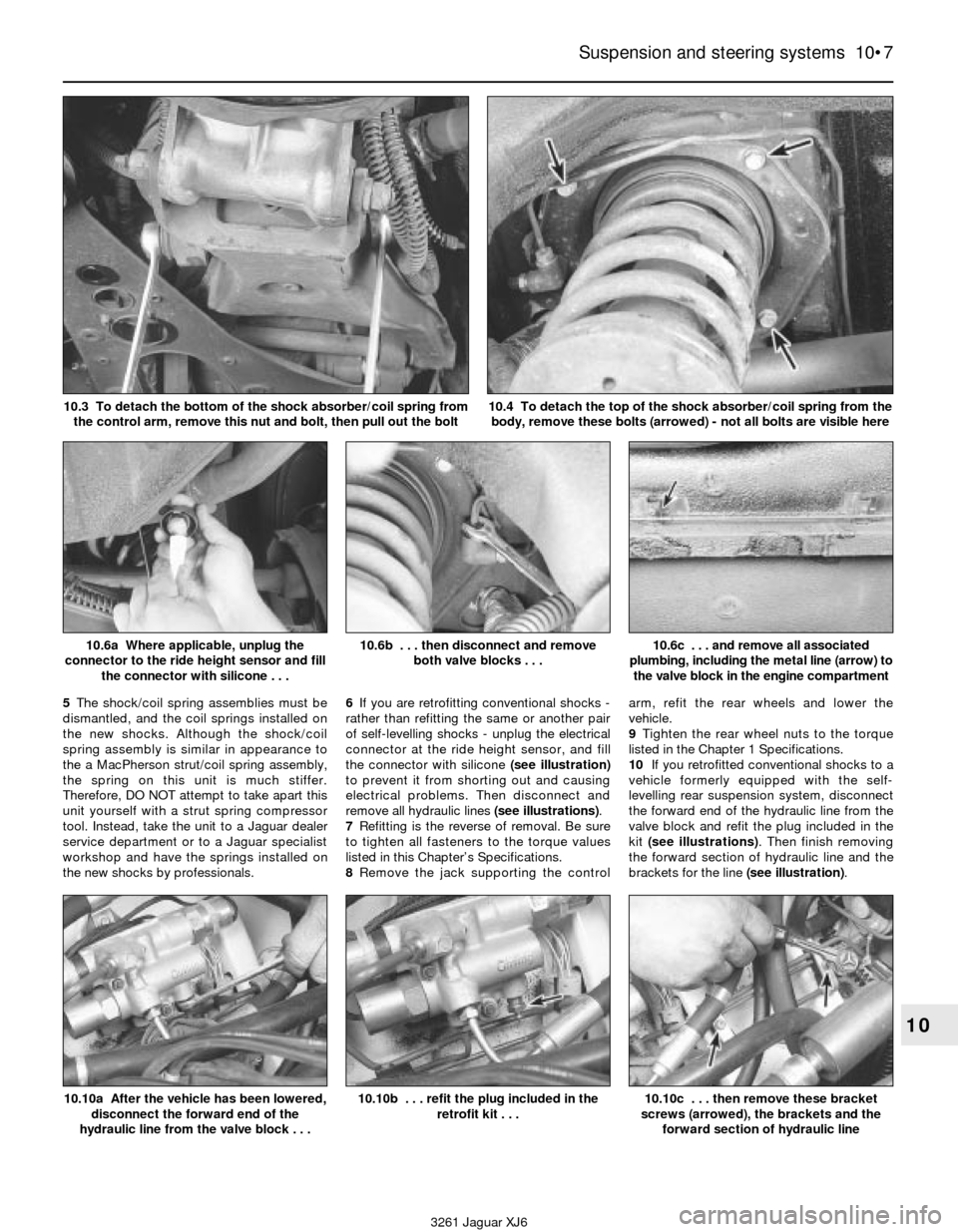
connector at the ride height sensor, and fill
the connector with silicone (see illustration)
to prevent it from shorting out and causing
electrical problems. Then disconnect and
remove all hydraulic lines (see illustrations).
7Refitting is the reverse of removal. Be sure
to tighten all fasteners to the torque values
listed in this Chapter’s Specifications.
8Remove the jack supporting the controlarm, refit the rear wheels and lower the
vehicle.
9Tighten the rear wheel nuts to the torque
listed in the Chapter 1 Specifications.
10If you retrofitted conventional shocks to a
vehicle formerly equipped with the self-
levelling rear suspension system, disconnect
the forward end of the hydraulic line from the
valve block and refit the plug included in the
kit (see illustrations). Then finish removing
the forward section of hydraulic line and the
brackets for the line (see illustration).
Suspension and steering systems 10•7
10
10.6a Where applicable, unplug the
connector to the ride height sensor and fill
the connector with silicone . . .10.6b . . . then disconnect and remove
both valve blocks . . .10.6c . . . and remove all associated
plumbing, including the metal line (arrow) to
the valve block in the engine compartment
3261 Jaguar XJ6 10.3 To detach the bottom of the shock absorber/coil spring from
the control arm, remove this nut and bolt, then pull out the bolt
10.4 To detach the top of the shock absorber/coil spring from the
body, remove these bolts (arrowed) - not all bolts are visible here
10.10a After the vehicle has been lowered,
disconnect the forward end of the
hydraulic line from the valve block . . .10.10b . . . refit the plug included in the
retrofit kit . . .10.10c . . . then remove these bracket
screws (arrowed), the brackets and the
forward section of hydraulic line
Page 144 of 227
11If you installed another pair of self-
levelling shocks, or removed and installed the
same pair of self-levelling shocks, be sure to
top up the power hydraulic system reservoir
(see Chapter 1).
11 Hub carrier (rear)-
removal and refitting
4
1Loosen the wheel nuts, raise the rear of the
vehicle and support it securely on axle stands.
Remove the wheel.
2Remove the rear caliper and brake pads,
the caliper bracket, the brake disc, the
handbrake cable and the handbrake shoe
assembly (see Chapter 9).
3Disconnect the outer end of the propshaft
from the hub carrier (see Chapter 8).
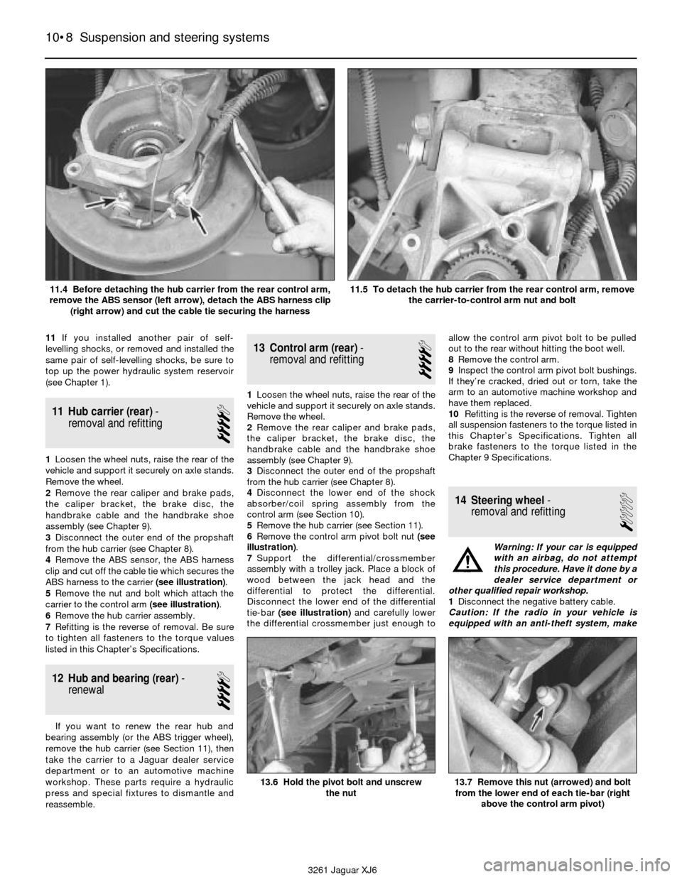
4Remove the ABS sensor, the ABS harness
clip and cut off the cable tie which secures the
ABS harness to the carrier (see illustration).
5Remove the nut and bolt which attach the
carrier to the control arm (see illustration).
6Remove the hub carrier assembly.
7Refitting is the reverse of removal. Be sure
to tighten all fasteners to the torque values
listed in this Chapter’s Specifications.
12 Hub and bearing (rear)-
renewal
4
If you want to renew the rear hub and
bearing assembly (or the ABS trigger wheel),
remove the hub carrier (see Section 11), then
take the carrier to a Jaguar dealer service
department or to an automotive machine
workshop. These parts require a hydraulic
press and special fixtures to dismantle and
reassemble.
13 Control arm (rear)-
removal and refitting
4
1Loosen the wheel nuts, raise the rear of the
vehicle and support it securely on axle stands.
Remove the wheel.
2Remove the rear caliper and brake pads,
the caliper bracket, the brake disc, the
handbrake cable and the handbrake shoe
assembly (see Chapter 9).
3Disconnect the outer end of the propshaft
from the hub carrier (see Chapter 8).
4Disconnect the lower end of the shock
absorber/coil spring assembly from the
control arm (see Section 10).
5Remove the hub carrier (see Section 11).
6Remove the control arm pivot bolt nut (see
illustration).
7Support the differential/crossmember
assembly with a trolley jack. Place a block of
wood between the jack head and the
differential to protect the differential.
Disconnect the lower end of the differential
tie-bar (see illustration)and carefully lower
the differential crossmember just enough toallow the control arm pivot bolt to be pulled
out to the rear without hitting the boot well.
8Remove the control arm.
9Inspect the control arm pivot bolt bushings.
If they’re cracked, dried out or torn, take the
arm to an automotive machine workshop and
have them replaced.
10Refitting is the reverse of removal. Tighten
all suspension fasteners to the torque listed in
this Chapter’s Specifications. Tighten all
brake fasteners to the torque listed in the
Chapter 9 Specifications.
14 Steering wheel-
removal and refitting
1
Warning: If your car is equipped
with an airbag, do not attempt
this procedure. Have it done by a
dealer service department or
other qualified repair workshop.
1Disconnect the negative battery cable.
Caution: If the radio in your vehicle is
equipped with an anti-theft system, make
10•8 Suspension and steering systems
13.6 Hold the pivot bolt and unscrew
the nut13.7 Remove this nut (arrowed) and bolt
from the lower end of each tie-bar (right
above the control arm pivot)
3261 Jaguar XJ6 11.4 Before detaching the hub carrier from the rear control arm,
remove the ABS sensor (left arrow), detach the ABS harness clip
(right arrow) and cut the cable tie securing the harness
11.5 To detach the hub carrier from the rear control arm, remove
the carrier-to-control arm nut and bolt