glove box JAGUAR XJ6 1997 2.G Workshop Manual
[x] Cancel search | Manufacturer: JAGUAR, Model Year: 1997, Model line: XJ6, Model: JAGUAR XJ6 1997 2.GPages: 227, PDF Size: 7.2 MB
Page 15 of 227
3261 Jaguar XJ6
Weekly checks0•15
Battery
Caution:Before carrying out any work on the
vehicle battery, read the precautions given in
"Safety first" at the start of this manual.
4Make sure that the battery tray is in good
condition, and that the clamp is tight.
Corrosion on the tray, retaining clamp and the
battery itself can be removed with a solution
of water and baking soda. Thoroughly rinse all
cleaned areas with water. Any metal parts
damaged by corrosion should be covered
with a zinc-based primer, then painted.
4Periodically (approximately every three
months), check the charge condition of the
battery as described in Chapter 5.
4If the battery is flat, and you need to jump
start your vehicle, see Roadside Repairs.
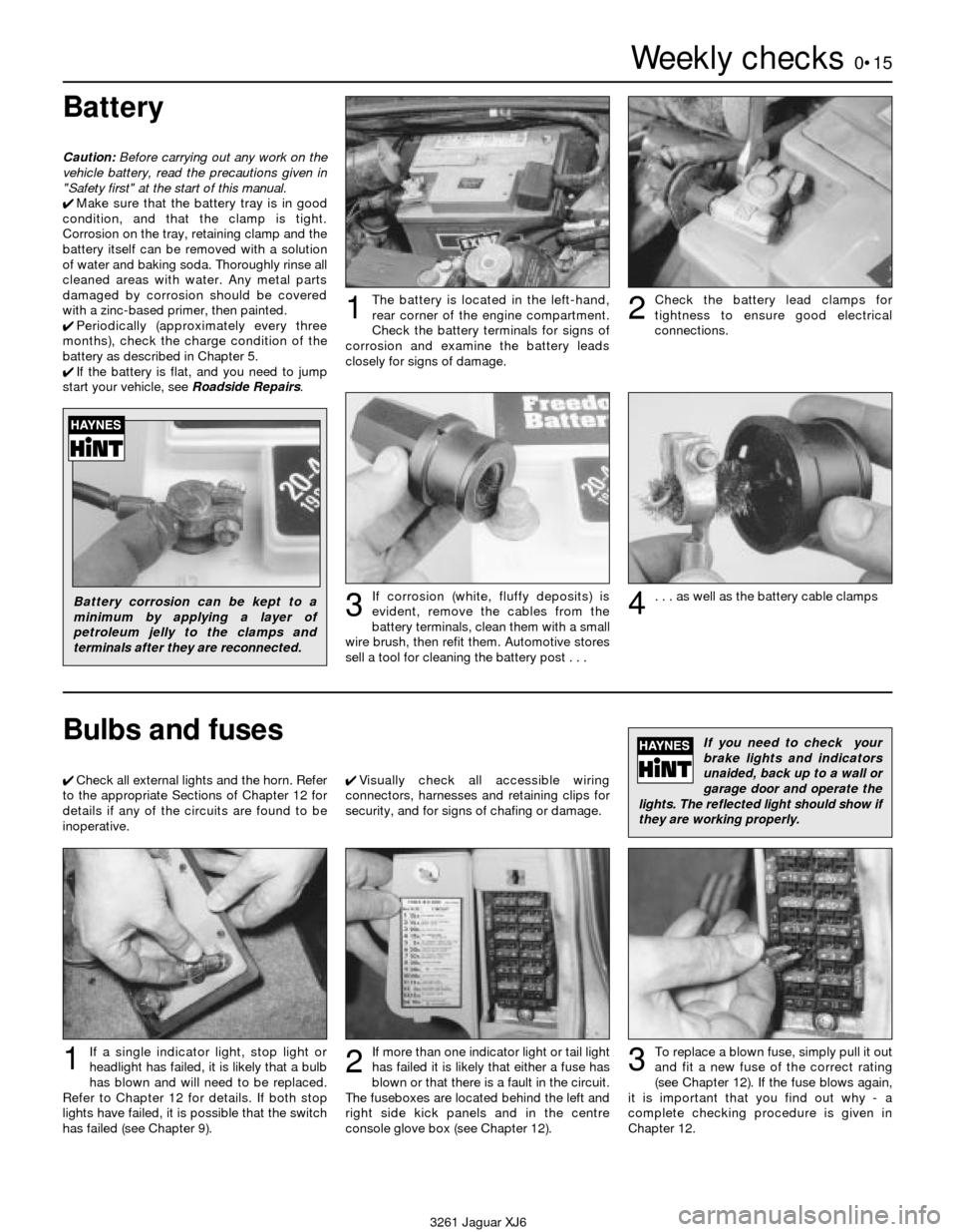
The battery is located in the left-hand,
rear corner of the engine compartment.
Check the battery terminals for signs of
corrosion and examine the battery leads
closely for signs of damage.1Check the battery lead clamps for
tightness to ensure good electrical
connections.2
Battery corrosion can be kept to a
minimum by applying a layer of
petroleum jelly to the clamps and
terminals after they are reconnected.If corrosion (white, fluffy deposits) is
evident, remove the cables from the
battery terminals, clean them with a small
wire brush, then refit them. Automotive stores
sell a tool for cleaning the battery post . . .3. . . as well as the battery cable clamps4
Bulbs and fuses
4Check all external lights and the horn. Refer
to the appropriate Sections of Chapter 12 for
details if any of the circuits are found to be
inoperative.4Visually check all accessible wiring
connectors, harnesses and retaining clips for
security, and for signs of chafing or damage.
If you need to check your
brake lights and indicators
unaided, back up to a wall or
garage door and operate the
lights. The reflected light should show if
they are working properly.
If a single indicator light, stop light or
headlight has failed, it is likely that a bulb
has blown and will need to be replaced.
Refer to Chapter 12 for details. If both stop
lights have failed, it is possible that the switch
has failed (see Chapter 9).If more than one indicator light or tail light
has failed it is likely that either a fuse has
blown or that there is a fault in the circuit.
The fuseboxes are located behind the left and
right side kick panels and in the centre
console glove box (see Chapter 12).
2
To replace a blown fuse, simply pull it out
and fit a new fuse of the correct rating
(see Chapter 12). If the fuse blows again,
it is important that you find out why - a
complete checking procedure is given in
Chapter 12.31
Page 80 of 227
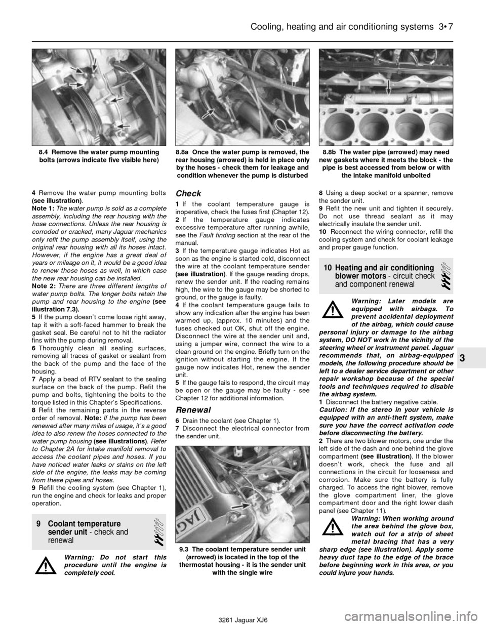
4Remove the water pump mounting bolts
(see illustration).
Note 1:The water pump is sold as a complete
assembly, including the rear housing with the
hose connections. Unless the rear housing is
corroded or cracked, many Jaguar mechanics
only refit the pump assembly itself, using the
original rear housing with all its hoses intact.
However, if the engine has a great deal of
years or mileage on it, it would be a good idea
to renew those hoses as well, in which case
the new rear housing can be installed.
Note 2:There are three different lengths of
water pump bolts. The longer bolts retain the
pump and rear housing to the engine(see
illustration 7.3).
5If the pump doesn’t come loose right away,
tap it with a soft-faced hammer to break the
gasket seal. Be careful not to hit the radiator
fins with the pump during removal.
6Thoroughly clean all sealing surfaces,
removing all traces of gasket or sealant from
the back of the pump and the face of the
housing.
7Apply a bead of RTV sealant to the sealing
surface on the back of the pump. Refit the
pump and bolts, tightening the bolts to the
torque listed in this Chapter’s Specifications.
8Refit the remaining parts in the reverse
order of removal. Note:If the pump has been
renewed after many miles of usage, it’s a good
idea to also renew the hoses connected to the
water pump housing(see illustrations). Refer
to Chapter 2A for intake manifold removal to
access the coolant pipes and hoses. If you
have noticed water leaks or stains on the left
side of the engine, the leaks may be coming
from these pipes and hoses.
9Refill the cooling system (see Chapter 1),
run the engine and check for leaks and proper
operation.
9 Coolant temperature
sender unit- check and
renewal
2
Warning: Do not start this
procedure until the engine is
completely cool.
Check
1If the coolant temperature gauge is
inoperative, check the fuses first (Chapter 12).
2If the temperature gauge indicates
excessive temperature after running awhile,
see the Fault finding section at the rear of the
manual.
3If the temperature gauge indicates Hot as
soon as the engine is started cold, disconnect
the wire at the coolant temperature sender
(see illustration). If the gauge reading drops,
renew the sender unit. If the reading remains
high, the wire to the gauge may be shorted to
ground, or the gauge is faulty.
4If the coolant temperature gauge fails to
show any indication after the engine has been
warmed up, (approx. 10 minutes) and the
fuses checked out OK, shut off the engine.
Disconnect the wire at the sender unit and,
using a jumper wire, connect the wire to a
clean ground on the engine. Briefly turn on the
ignition without starting the engine. If the
gauge now indicates Hot, renew the sender
unit.
5If the gauge fails to respond, the circuit may
be open or the gauge may be faulty - see
Chapter 12 for additional information.
Renewal
6Drain the coolant (see Chapter 1).
7Disconnect the electrical connector from
the sender unit.8Using a deep socket or a spanner, remove
the sender unit.
9Refit the new unit and tighten it securely.
Do not use thread sealant as it may
electrically insulate the sender unit.
10Reconnect the wiring connector, refill the
cooling system and check for coolant leakage
and proper gauge function.
10 Heating and air conditioning
blower motors- circuit check
and component renewal
3
Warning: Later models are
equipped with airbags. To
prevent accidental deployment
of the airbag, which could cause
personal injury or damage to the airbag
system, DO NOT work in the vicinity of the
steering wheel or instrument panel. Jaguar
recommends that, on airbag-equipped
models, the following procedure should be
left to a dealer service department or other
repair workshop because of the special
tools and techniques required to disable
the airbag system.
1Disconnect the battery negative cable.
Caution: If the stereo in your vehicle is
equipped with an anti-theft system, make
sure you have the correct activation code
before disconnecting the battery.
2There are two blower motors, one under the
left side of the dash and one behind the glove
compartment (see illustration). If the blower
doesn’t work, check the fuse and all
connections in the circuit for looseness and
corrosion. Make sure the battery is fully
charged. To access the right blower, remove
the glove compartment liner, the glove
compartment door and the right lower dash
panel (see Chapter 11).
Warning: When working around
the area behind the glove box,
watch out for a strip of sheet
metal bracing that has a very
sharp edge (see illustration). Apply some
heavy duct tape to the edge of the brace
before beginning work in this area, or you
could injure your hands.
Cooling, heating and air conditioning systems 3•7
3
8.4 Remove the water pump mounting
bolts (arrows indicate five visible here)8.8a Once the water pump is removed, the
rear housing (arrowed) is held in place only
by the hoses - check them for leakage and
condition whenever the pump is disturbed8.8b The water pipe (arrowed) may need
new gaskets where it meets the block - the
pipe is best accessed from below or with
the intake manifold unbolted
9.3 The coolant temperature sender unit
(arrowed) is located in the top of the
thermostat housing - it is the sender unit
with the single wire
3261 Jaguar XJ6
Page 81 of 227

3Remove the screws holding the cruise-
control ECU in place (see illustrations), then
remove the four screws holding the ECU
mounting plate in place.
4Disconnect the vacuum lines and electrical
connectors at the blower housing, identifying
each connection with marked masking tape
for reassembly, or write down the colour
codes of the vacuum tubing. Remove the duct
tape connecting the blower housing to the
duct from the heater/air conditioning unit.
5Remove the two bolts holding the top of the
blower housing to the cowl (see illustration).
6Pull down and back on the housing until itsqueezes past the metal brace below it (see
illustration).It will take some force at first.
7To access the left blower motor, remove
the left-hand brace rod from the steering
column forward to the body(see illustration),
then repeat Steps 4 and 5 on the left blower
housing. The blower housing should now drop
straight down and out.
8If the blower motor does not operate,
disconnect the electrical connectors at the
blower motor and connect the black wire
terminal to chassis ground, and the purple
wire terminal to a fused source of battery
voltage. If the blower doesn’t operate, itshould be renewed. If it does operate, there is
a problem in the feed or earth circuit.
9If the motor is good, but doesn’t operate at
any speed, the problem could be in the
heater/air conditioning control assembly or
the heating/air conditioning computer.
Diagnosis either of these electronic com-
ponents is beyond the scope of the home
mechanic, and should be referred to your
Jaguar dealer or other qualified repair facility.
10If either blower motor must be renewed,
remove the five clips and one screw holding
the blower housing halves together (see
illustration).
3•8 Cooling, heating and air conditioning systems
10.2a The right blower housing (arrowed)
is located behind the glove box area
of the dash10.2b Apply heavy duct tape to the sharp
edge of this brace (dotted line) when
working behind the glove box area of the
dash - the metal is very sharp10.3a Remove the screw (A) holding the
wiring harness in place, then remove the
two lower cruise-control ECU screws (B) . . .
10.3b . . . then remove the upper ECU
screw (arrowed) and pull down the ECU,
then remove the ECU mounting plate10.5 Two bolts (arrow indicates the left
bolt) hold the top of the blower housing
to the cowl10.6 Pull down and out on the housing
until it clears the sheet metal brace
below it
3261 Jaguar XJ6 10.7 Remove this brace rod (small arrow)
for clearance to remove the left blower
motor housing (large arrow)
10.10 Remove the five clips (two shown
here with arrows) and one screw holding
the halves of the housing together
Page 82 of 227

11Separate the housing halves and pull up
the plastic plate holding the motor and fan
(see illustration). The fan doesn’t come off
the motor, but loosen the clamp-bolt on the
motor’s mount bracket and slide the motor
and fan out for renewal (see illustration).
Note:Some 1988 models had problems with
cracking of the fan blades and noise from the
blowers. These blowers and fans have been
superseded with improved parts, available
from your Jaguar dealer.
12When either blower housing is separated,
you’ll find two relays mounted inside (see
illustration). These are the blower isolation
relay and blower relay. Before refitting the
blower housing in the car, refer to Chapter 12
for testing of these relays.
13Refitting is the reverse of removal. Check
for proper operation.11 Heater core-
removal and refitting
4
Warning: Later model vehicles
are equipped with airbags. To
prevent the accidental deploy-
ment of the airbag, which could
cause personal injury or damage to the
airbag system, DO NOT work in the vicinity
of the steering wheel or instrument panel.
The manufacturer recommends that, on
airbag-equipped models, the following
procedure should be left to a dealer service
department or other repair workshop
because of the special tools and techniques
required to disable the airbag system.1Disconnect the battery negative cable.
Caution: If the stereo in your vehicle is
equipped with an anti-theft system, make
sure you have the correct activation code
before disconnecting the battery.
2Drain the cooling system (see Chapter 1).
Disconnect the heater hoses where they enter
the bulkhead (see illustration). Note:Use
compressed air in one of the pipes to blow out
any remaining coolant and collect it. This will
prevent any spills on the carpeting when the
heater core is removed. Plug the pipes to
prevent any remaining coolant from spilling out.
3Refer to Chapter 11 for removal of the
under-dash panels on both the driver and
passenger sides, and removal of the glovebox.
Warning: When working around
the area behind the glove box,
watch out for a strip of sheet
Cooling, heating and air conditioning systems 3•9
3
3261 Jaguar XJ6 10.11a Separate the housing halves - the blower motor (arrowed)
is attached to a plastic plate sandwiched between the
two housing halves
10.11b Loosen the clamp bolt (arrowed) on the motor bracket and
then pull the motor and fan out as an assembly
10.12 Inside the blower case are the blower and isolation relays
(arrowed) - while the case is apart, test these relays for
proper operation11.2 Disconnect the heater hoses from the pipes at the bulkhead
(small arrows) - the large arrow indicates the evaporator case
retaining nut
Page 90 of 227
special electrical device that provides circuit
protection by switching off the ignition and
fuel pump upon impact in the event of vehicle
collision. Later Jaguar models are equipped
with an additional specialised inertia switch.
This later device switches OFF all ignition fed
circuits, locks the fuel filler cap, locks the boot
(only if doors are locked) and unlocks the
doors if they are locked during the accident.
All these functions are directed by the inertia
switch. The inertia switch is located behind
the left kick panel. Refer to Chapter 12 for
more information.
Exhaust system
The exhaust system includes an exhaust
manifold equipped with an exhaust oxygen
sensor, a catalytic converter, an exhaust pipe,
and a silencer.
The catalytic converter is an emission
control device added to the exhaust system to
reduce pollutants. A single-bed converter is
used in combination with a three-way
(reduction) catalyst. See Chapter 6 for more
information regarding the catalytic converter.
2 Fuel pressure relief
1
Warning: Petrol is extremely
flammable, so take extra
precautions when you work on
any part of the fuel system.
Don’t smoke or allow open flames or bare
light bulbs near the work area, and don’t
work in a garage where a natural gas-type
appliance (such as a water heater or a
clothes dryer) with a pilot light is present.
Since petrol is carcinogenic, wear latex
gloves when there’s a possibility of being
exposed to fuel, and, if you spill any fuel on
your skin, rinse it off immediately with soap
and water. Mop up any spills immediately
and do not store fuel-soaked rags wherethey could ignite. The fuel system is under
constant pressure, so, if any fuel lines are
to be disconnected, the fuel pressure in
the system must be relieved first. When
you perform any kind of work on the fuel
system, wear safety glasses and have a
Class B type fire extinguisher on hand.
1Before servicing any fuel system
component, you must relieve the fuel pressure
to minimise the risk of fire or personal injury.
2Remove the fuel filler cap - this will relieve
any pressure built up in the tank.
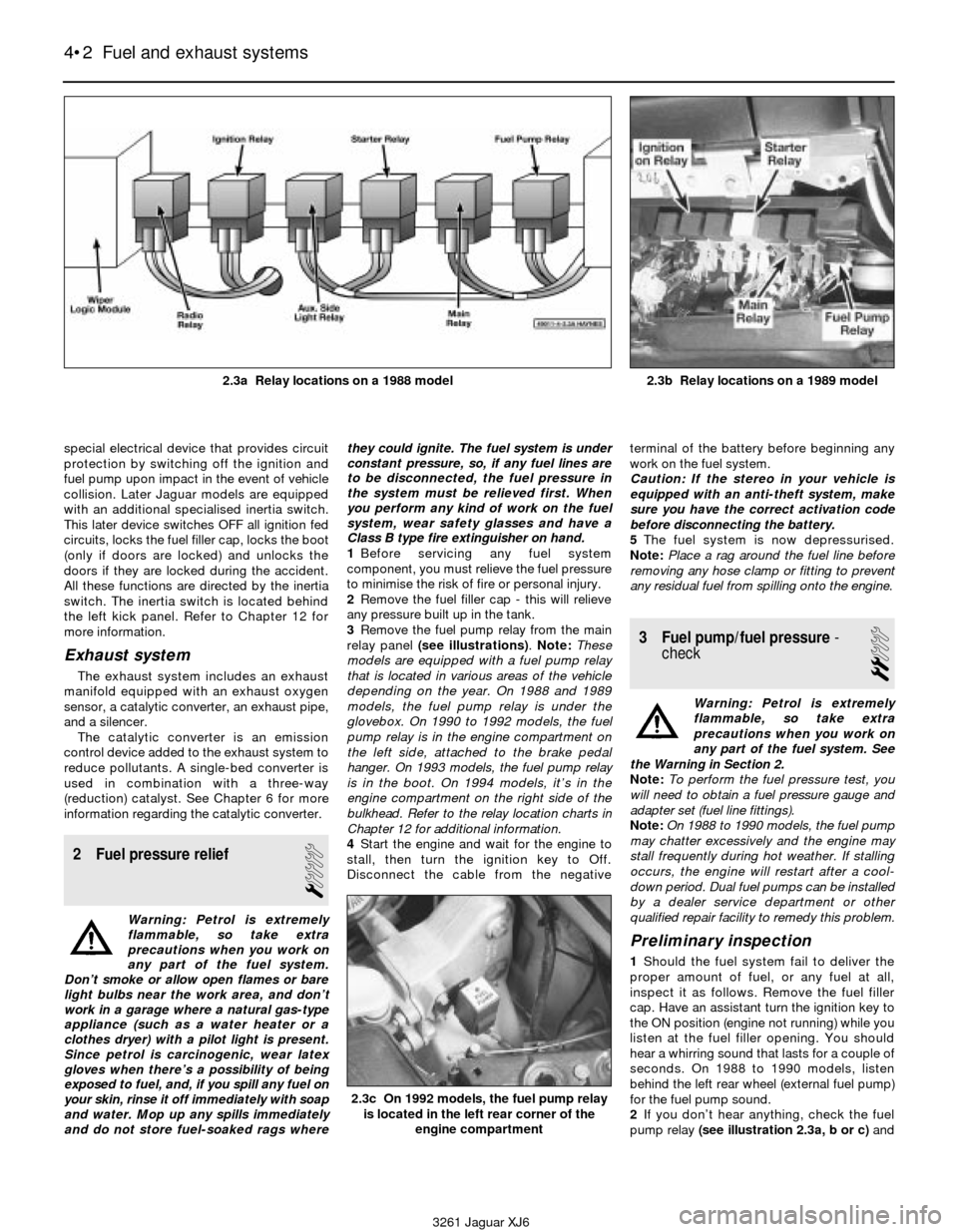
3Remove the fuel pump relay from the main
relay panel (see illustrations). Note:These
models are equipped with a fuel pump relay
that is located in various areas of the vehicle
depending on the year. On 1988 and 1989
models, the fuel pump relay is under the
glovebox. On 1990 to 1992 models, the fuel
pump relay is in the engine compartment on
the left side, attached to the brake pedal
hanger. On 1993 models, the fuel pump relay
is in the boot. On 1994 models, it’s in the
engine compartment on the right side of the
bulkhead. Refer to the relay location charts in
Chapter 12 for additional information.
4Start the engine and wait for the engine to
stall, then turn the ignition key to Off.
Disconnect the cable from the negativeterminal of the battery before beginning any
work on the fuel system.
Caution: If the stereo in your vehicle is
equipped with an anti-theft system, make
sure you have the correct activation code
before disconnecting the battery.
5The fuel system is now depressurised.
Note:Place a rag around the fuel line before
removing any hose clamp or fitting to prevent
any residual fuel from spilling onto the engine.
3 Fuel pump/fuel pressure-
check
2
Warning: Petrol is extremely
flammable, so take extra
precautions when you work on
any part of the fuel system. See
the Warning in Section 2.
Note: To perform the fuel pressure test, you
will need to obtain a fuel pressure gauge and
adapter set (fuel line fittings).
Note: On 1988 to 1990 models, the fuel pump
may chatter excessively and the engine may
stall frequently during hot weather. If stalling
occurs, the engine will restart after a cool-
down period. Dual fuel pumps can be installed
by a dealer service department or other
qualified repair facility to remedy this problem.
Preliminary inspection
1Should the fuel system fail to deliver the
proper amount of fuel, or any fuel at all,
inspect it as follows. Remove the fuel filler
cap. Have an assistant turn the ignition key to
the ON position (engine not running) while you
listen at the fuel filler opening. You should
hear a whirring sound that lasts for a couple of
seconds. On 1988 to 1990 models, listen
behind the left rear wheel (external fuel pump)
for the fuel pump sound.
2If you don’t hear anything, check the fuel
pump relay (see illustration 2.3a, b or c)and
4•2 Fuel and exhaust systems
2.3c On 1992 models, the fuel pump relay
is located in the left rear corner of the
engine compartment
3261 Jaguar XJ6 2.3a Relay locations on a 1988 model
2.3b Relay locations on a 1989 model
Page 112 of 227
components identified. When servicing the
engine or emissions systems, the VECI label
in your particular vehicle should always be
checked for up-to-date information.
2 Electronic control system
and ECU
General description
Note: These models are susceptible to ECU
damage if water is allowed to build up in the
front cowl drain and overspill into the dash
area near the computer. Inspect and clear the
front cowl drain as a regular maintenance item
to keep the water draining properly. Remove
the duckbill-type rubber hose and inspect it
for clogging, collapsing or deterioration.
1The Lucas LH Engine Management system
controls the fuel injection system by means of
a microcomputer known as the Electronic
Control unit (ECU).
2The ECU receives signals from various
sensors which monitor changing engine
operating conditions such as intake air mass,
intake air temperature, coolant temperature,
engine rpm, acceleration/deceleration,
exhaust oxygen content, etc. These signals
are utilised by the ECU to determine the
correct injection duration.
3The system is analogous to the central
nervous system in the human body: The
sensors (nerve endings) constantly relay
signals to the ECU (brain), which processes
the data and, if necessary, sends out a
command to change the operating
parameters of the engine (body).
4Here’s a specific example of how one
portion of this system operates: An oxygen
sensor, located in the exhaust manifold,
constantly monitors the oxygen content of the
exhaust gas. If the percentage of oxygen in
the exhaust gas is incorrect, an electrical
signal is sent to the ECU. The ECU takes this
information, processes it and then sends a
command to the fuel injection system telling it
to change the air/fuel mixture. This happens in
a fraction of a second and it goes on
continuously when the engine is running. The
end result is an air/fuel mixture ratio which is
constantly maintained at a predetermined
ratio, regardless of driving conditions.
5In the event of a sensor malfunction, a
backup circuit will take over to provide
driveability until the problem is identified and
fixed.
Precautions
6Follow these steps:
a) Always disconnect the power by either
turning off the ignition switch or
disconnecting the battery terminals before
removing electrical connectors.
Warning: Later models are
equipped with airbags. To
prevent accidental deployment ofthe airbag, which could cause personal
injury, DO NOT work in the vicinity of the
steering column or instrument panel. The
manufacturer recommends that, on airbag
equipped models, the following procedure
should be left to a dealer service
department or other repair workshop
because of the special tools and techniques
required to disable the airbag system.
Caution: If the stereo in your vehicle is
equipped with an anti-theft system, make
sure you have the correct activation code
before disconnecting the battery.
b) When refitting a battery, be particularly
careful to avoid reversing the positive and
negative battery cables. Also, make sure
the ignition key is in the Off position when
connecting or disconnecting the battery.
c) Do not subject EFI components,
emissions-related components or the
ECU to severe impact during removal or
refitting.
d) Do not be careless during fault diagnosis.
Even slight terminal contact can invalidate
a testing procedure and damage one of
the numerous transistor circuits.
e) Never attempt to work on the ECU or
open the ECU cover. The ECU is
protected by a government-mandated
extended warranty that will be nullified if
you tamper with or damage the ECU.
f) If you are inspecting electronic control
system components during rainy weather,
make sure that water does not enter any
part. When washing the engine
compartment, do not spray these parts or
their electrical connectors with water.
g) These models are susceptible to ECU
damage if water is allowed to build up in
the front cowl drain and overspill into the
dash area. Inspect and clear the front
cowl drain system as a regular
maintenance item to keep the water
draining properly. Remove the duckbill
type rubber hose and inspect it for
clogging, collapsing or deterioration.
ECU removal and refitting
7Disconnect the negative cable from the
battery (see Chapter 5).
Warning: Later models are
equipped with airbags. To
prevent the accidental deploy-
ment of the airbag, which could
cause personal injury, DO NOT work in the
vicinity of the steering column or
instrument panel. The manufacturer
recommends that, on airbag equipped
models, the following procedure should be
left to a dealer service department or other
repair workshop because of the special
tools and techniques required to disable
the airbag system.
Caution: If the stereo in your vehicle is
equipped with an anti-theft system, make
sure you have the correct activation code
before disconnecting the battery.8Remove the lower instrument panel on the
passenger side under the glove compartment
(see Chapter 11).
9Remove the glove compartment from the
passenger compartment (see Chapter 11).
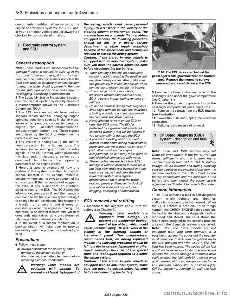
10Remove the screws from the ECU bracket
(see illustration).
11Lower the ECU and unplug the electrical
connectors.
12Refitting is the reverse of removal.
3 On Board Diagnosis (OBD)
system- description and fault
code access
2
Note: 1990 and 1991 models may set
Code 69 erroneously. If the battery voltage
drops sufficiently and the ignition key is
switched quickly from OFF to START, battery
voltage will be lowered and during cranking
causing a delayed park/neutral signal from the
decoder module to the ECU. Check all the
battery connections and the condition of the
battery and then check the rotary switch
adjustment in Chapter 7 to remedy this code.
General information
1The ECU contains a built-in self-diagnosis
system which detects and identifies
malfunctions occurring in the network. When
the ECU detects a problem, three things
happen: the CHECK ENGINE light comes on,
the fault is identified and a diagnostic code is
recorded and stored. The ECU stores the
failure code assigned to the specific problem
area until the diagnosis system is cancelled.
Note: 1988 and 1989 models are not
equipped with long term memory. It is
possible to access the codes but the operator
must remember to NOT turn the ignition key to
the OFF position after the CHECK ENGINE
light has been noticed. The codes will be lost
and it will be necessary to start the engine and
operate the vehicle through a complete drive
cycle to allow the fault code(s) to be set once
again. Instead of turning the ignition key to the
OFF position, simply stop at position II (key
ON but engine not running) to retain the fault
codes.
6•2 Emissions and engine control systems
3261 Jaguar XJ6
2.10 The ECU is located behind the
passenger’s side glovebox near the footrest
area. Remove the mounting screws
(arrowed) and carefully lower the ECU
Page 161 of 227
26 Dashboard trim panels-
removal and refitting
2
Warning: Later models are
equipped with airbags. To
prevent the accidental deploy-
ment of the airbag, which could
cause personal injury or damage to the
airbag system, DO NOT work in the vicinity
of the steering column or instrument panel.
The manufacturer recommends that, on
airbag equipped models, the following
procedure should be left to a dealer service
department or other repair workshop
because of the special tools and techniques
required to disable the airbag system.
Caution: If the stereo in your vehicle is
equipped with an anti-theft system, make
sure you have the correct activation code
before disconnecting the battery
Knee bolster
1Knee bolsters are located on the lower half
of the instrument panel on the driver and
passenger sides of the vehicle. The removal of
these covers will allow access to a variety of
electrical, heating and air conditioning
components.
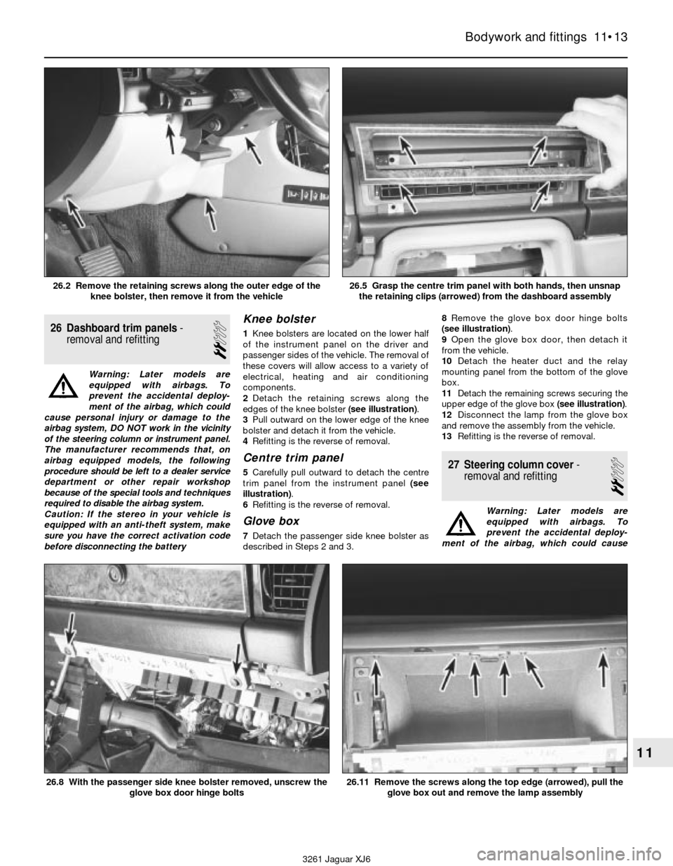
2Detach the retaining screws along the
edges of the knee bolster (see illustration).
3Pull outward on the lower edge of the knee
bolster and detach it from the vehicle.
4Refitting is the reverse of removal.
Centre trim panel
5Carefully pull outward to detach the centre
trim panel from the instrument panel (see
illustration).
6Refitting is the reverse of removal.
Glove box
7Detach the passenger side knee bolster as
described in Steps 2 and 3.8Remove the glove box door hinge bolts
(see illustration).
9Open the glove box door, then detach it
from the vehicle.
10Detach the heater duct and the relay
mounting panel from the bottom of the glove
box.
11Detach the remaining screws securing the
upper edge of the glove box (see illustration).
12Disconnect the lamp from the glove box
and remove the assembly from the vehicle.
13Refitting is the reverse of removal.
27 Steering column cover-
removal and refitting
2
Warning: Later models are
equipped with airbags. To
prevent the accidental deploy-
ment of the airbag, which could cause
Bodywork and fittings 11•13
11
3261 Jaguar XJ6 26.2 Remove the retaining screws along the outer edge of the
knee bolster, then remove it from the vehicle
26.5 Grasp the centre trim panel with both hands, then unsnap
the retaining clips (arrowed) from the dashboard assembly
26.8 With the passenger side knee bolster removed, unscrew the
glove box door hinge bolts26.11 Remove the screws along the top edge (arrowed), pull the
glove box out and remove the lamp assembly
Page 164 of 227

to earth somewhere in that area, probably
where the insulation has rubbed through. The
same test can be performed on each
component in the circuit, even a switch.
Earth check
Perform an earth test to check whether a
component is properly earthed. Disconnect
the battery and connect one lead of a self-
powered test light, known as a continuity
tester, to a known good earth. Connect the
other lead to the wire or earth connection
being tested. If the bulb goes on, the earth is
good. If the bulb does not go on, the earth is
not good.
Continuity check
A continuity check is done to determine if
there are any breaks in a circuit - if it is
passing electricity properly. With the circuit off
(no power in the circuit), a self-powered
continuity tester can be used to check the
circuit. Connect the test leads to both ends of
the circuit (or to the “power” end and a good
earth), and if the test light comes on the circuit
is passing current properly. If the light doesn’t
come on, there is a break somewhere in the
circuit. The same procedure can be used
to test a switch, by connecting the continuity
tester to the power in and power out sides of
the switch. With the switch turned On, the test
light should come on.
Finding an open circuit
When diagnosing for possible open circuits,
it is often difficult to locate them by sight
because oxidation or terminal misalignment
are hidden by the electrical connectors.
Merely wiggling an electrical connector on a
sensor or in the wiring harness may correct
the open circuit condition. Remember this
when an open circuit is indicated when
diagnosing a circuit. Intermittent problems
may also be caused by oxidised or loose
connections.Electrical fault finding is simple if you keep
in mind that all electrical circuits are basically
electricity running from the battery, through
the wires, switches, relays, fuses and fusible
links to each electrical component (light bulb,
motor, etc.) and to earth, from which it is
passed back to the battery. Any electrical
problem is an interruption in the flow of
electricity to and from the battery.
3 Fuses- general information
The electrical circuits of the vehicle are
protected by a combination of fuses, circuit
breakers and In-line fuses. The fuse blocks
are located in the left and right side kick
panels and in the centre console glove box
(see illustrations).
Each of the fuses is designed to protect a
specific circuit, and the various circuits are
identified on the fuse panel cover.
Miniaturised fuses are employed in the fuse
blocks. These compact fuses, with blade
terminal design, allow fingertip removal and
renewal. If an electrical component fails,
always check the fuse first. The best way tocheck the fuses is with a test light. Check for
power at the exposed terminal tips of each
fuse. If power is present on one side of the
fuse but not the other, the fuse is blown. A
blown fuse can be confirmed by visual
inspection (see illustration).
Be sure to renew blown fuses with the
correct type. Fuses of different ratings are
physically interchangeable, but only fuses of
the proper rating should be used. Replacing a
fuse with one of a higher or lower value than
specified is not recommended. Each electrical
circuit needs a specific amount of protection.
The amperage value of each fuse is moulded
into the fuse body.
If the renewal fuse immediately fails, don’t
renew it again until the cause of the problem
is isolated and corrected. In most cases, this
will be a short circuit in the wiring caused by a
broken or deteriorated wire.
4 In-line fuses-
general information
Some circuits are protected by in-line
fuses. In-line fuses are used in such circuits
as the windscreen wiper system, headlight
12•2 Body electrical system
3261 Jaguar XJ6 3.1a The left side fusebox is located in the passenger’s side kick
panel, behind the fuse panel cover
3.1b The right side fusebox is located in the driver’s side kick
panel, behind the fuse panel cover
3.1c A third fusebox is located in the
centre console glove box3.3 When a fuse blows, the metal element
between the terminals melts - the fuse on
the left is blown, the one on the right is ok
Page 177 of 227
Later models are equipped with a
Supplemental Restraint System (SRS), more
commonly known as an airbag. This system is
designed to protect the driver, and on 1994
models, the passenger from serious injury in
the event of a head-on or frontal collision. It
consists of an airbag module in the centre of
the steering wheel and a passenger airbag
module on the right side of the dash above
the glove box on 1994 models.
The airbag modules contain an inflater and
a sensor assembly which activates from
impact energy that is transmitted through the
body and steering column upon impact or
collision.
DO NOT try to dismantle or remove any
component in the vicinity of the steering
column or instrument panel on models
equipped with air bags. Serious personalinjury or damage may result. The
manufacturer recommends that, on airbag
equipped models, service which requires
removal of any component in the vicinity of
the instrument panel or steering column
should be left to a dealer service department
or other properly equipped repair facility
because of the special tools and techniques
required to disable the air bag system.
29 Wiring diagrams-
general information
Since it isn’t possible to include a complete
wiring diagram for every year covered by this
manual, the following diagrams are those that
are typical and most commonly needed.Prior to diagnosing any circuits, check the
fuse and circuit breakers (if equipped) to make
sure they are in good condition. Make sure
the battery is properly charged and has clean,
tight cable connections (see Chapter 1).
When checking the wiring system, make
sure that all electrical connectors are clean,
with no broken or loose pins. When
unplugging an electrical connector, do not
pull on the wires, only on the connector
housings themselves.
Body electrical system 12•15
12
3261 Jaguar XJ6 Wiring diagrams commence overleaf
Page 219 of 227
3261 Jaguar XJ6
REF•18Glossary of technical terms
A
ABS (Anti-lock brake system)A system,
usually electronically controlled, that senses
incipient wheel lockup during braking and
relieves hydraulic pressure at wheels that are
about to skid.
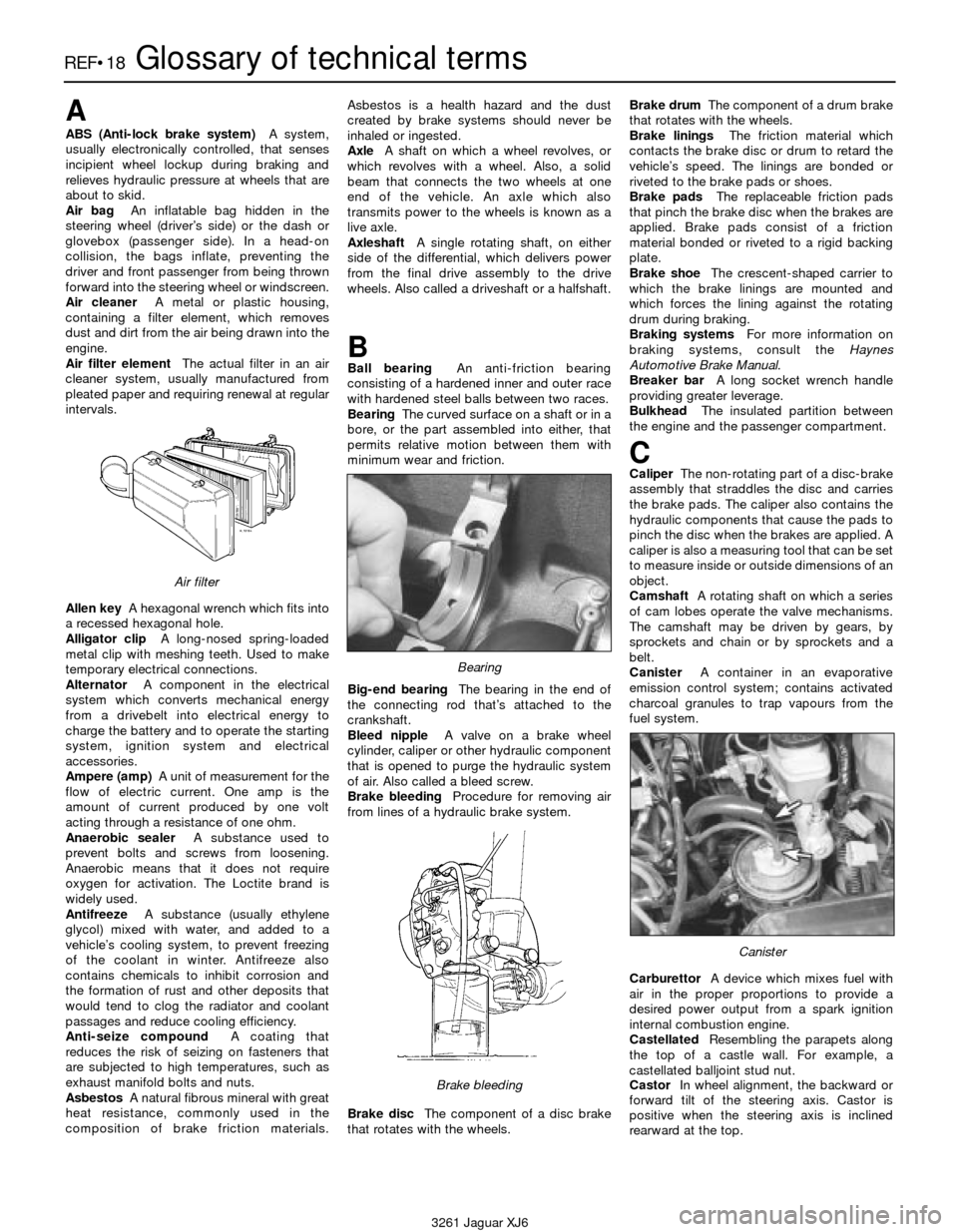
Air bag An inflatable bag hidden in the
steering wheel (driver’s side) or the dash or
glovebox (passenger side). In a head-on
collision, the bags inflate, preventing the
driver and front passenger from being thrown
forward into the steering wheel or windscreen.
Air cleanerA metal or plastic housing,
containing a filter element, which removes
dust and dirt from the air being drawn into the
engine.
Air filter elementThe actual filter in an air
cleaner system, usually manufactured from
pleated paper and requiring renewal at regular
intervals.
Allen keyA hexagonal wrench which fits into
a recessed hexagonal hole.
Alligator clipA long-nosed spring-loaded
metal clip with meshing teeth. Used to make
temporary electrical connections.
AlternatorA component in the electrical
system which converts mechanical energy
from a drivebelt into electrical energy to
charge the battery and to operate the starting
system, ignition system and electrical
accessories.
Ampere (amp)A unit of measurement for the
flow of electric current. One amp is the
amount of current produced by one volt
acting through a resistance of one ohm.
Anaerobic sealerA substance used to
prevent bolts and screws from loosening.
Anaerobic means that it does not require
oxygen for activation. The Loctite brand is
widely used.
AntifreezeA substance (usually ethylene
glycol) mixed with water, and added to a
vehicle’s cooling system, to prevent freezing
of the coolant in winter. Antifreeze also
contains chemicals to inhibit corrosion and
the formation of rust and other deposits that
would tend to clog the radiator and coolant
passages and reduce cooling efficiency.
Anti-seize compoundA coating that
reduces the risk of seizing on fasteners that
are subjected to high temperatures, such as
exhaust manifold bolts and nuts.
AsbestosA natural fibrous mineral with great
heat resistance, commonly used in the
composition of brake friction materials.Asbestos is a health hazard and the dust
created by brake systems should never be
inhaled or ingested.
AxleA shaft on which a wheel revolves, or
which revolves with a wheel. Also, a solid
beam that connects the two wheels at one
end of the vehicle. An axle which also
transmits power to the wheels is known as a
live axle.
AxleshaftA single rotating shaft, on either
side of the differential, which delivers power
from the final drive assembly to the drive
wheels. Also called a driveshaft or a halfshaft.
BBall bearingAn anti-friction bearing
consisting of a hardened inner and outer race
with hardened steel balls between two races.
BearingThe curved surface on a shaft or in a
bore, or the part assembled into either, that
permits relative motion between them with
minimum wear and friction.
Big-end bearingThe bearing in the end of
the connecting rod that’s attached to the
crankshaft.
Bleed nippleA valve on a brake wheel
cylinder, caliper or other hydraulic component
that is opened to purge the hydraulic system
of air. Also called a bleed screw.
Brake bleedingProcedure for removing air
from lines of a hydraulic brake system.
Brake discThe component of a disc brake
that rotates with the wheels.Brake drumThe component of a drum brake
that rotates with the wheels.
Brake liningsThe friction material which
contacts the brake disc or drum to retard the
vehicle’s speed. The linings are bonded or
riveted to the brake pads or shoes.
Brake padsThe replaceable friction pads
that pinch the brake disc when the brakes are
applied. Brake pads consist of a friction
material bonded or riveted to a rigid backing
plate.
Brake shoeThe crescent-shaped carrier to
which the brake linings are mounted and
which forces the lining against the rotating
drum during braking.
Braking systemsFor more information on
braking systems, consult the Haynes
Automotive Brake Manual.
Breaker barA long socket wrench handle
providing greater leverage.
BulkheadThe insulated partition between
the engine and the passenger compartment.
CCaliperThe non-rotating part of a disc-brake
assembly that straddles the disc and carries
the brake pads. The caliper also contains the
hydraulic components that cause the pads to
pinch the disc when the brakes are applied. A
caliper is also a measuring tool that can be set
to measure inside or outside dimensions of an
object.
CamshaftA rotating shaft on which a series
of cam lobes operate the valve mechanisms.
The camshaft may be driven by gears, by
sprockets and chain or by sprockets and a
belt.
CanisterA container in an evaporative
emission control system; contains activated
charcoal granules to trap vapours from the
fuel system.
CarburettorA device which mixes fuel with
air in the proper proportions to provide a
desired power output from a spark ignition
internal combustion engine.
CastellatedResembling the parapets along
the top of a castle wall. For example, a
castellated balljoint stud nut.
CastorIn wheel alignment, the backward or
forward tilt of the steering axis. Castor is
positive when the steering axis is inclined
rearward at the top.
Canister
Brake bleeding
Bearing
Air filter