service JAGUAR XJ6 1997 2.G Workshop Manual
[x] Cancel search | Manufacturer: JAGUAR, Model Year: 1997, Model line: XJ6, Model: JAGUAR XJ6 1997 2.GPages: 227, PDF Size: 7.2 MB
Page 1 of 227

3261 Jaguar XJ6
Models covered
Jaguar XJ6 models with 3.2 litre (3239 cc), 3.6 litre (3590 cc) & 4.0 litre (3980 cc)
six-cylinder in-line dohc petrol engines and automatic transmission
Covers most features of Daimler 3.6 and 4.0 litre models
Does not cover 2.9 litre (2919 cc) sohc engine or manual transmission
Does not cover XJR models or revised Jaguar/Daimler model ranges introduced September 1994
Jaguar XJ6
Service and Repair Manual
Mike Stubblefield
© Haynes Publishing 1997
A book in the Haynes Service and Repair Manual Series
All rights reserved. No part of this book may be reproduced or transmitted
in any form or by any means, electronic or mechanical, including
photocopying, recording or by any information storage or retrieval system,
without permission in writing from the copyright holder.
ISBN1 85960 261 4
British Library Cataloguing in Publication Data
A catalogue record for this book is available from the British Library.Printed by J H Haynes & Co. Ltd, Sparkford, Nr Yeovil,
Somerset BA22 7JJ
Haynes Publishing
Sparkford, Nr Yeovil, Somerset BA22 7JJ, England
Haynes North America, Inc
861 Lawrence Drive, Newbury Park, California 91320, USA
Editions Haynes S.A.
147/149, rue Saint Honoré, 75001 PARIS, France
Haynes Publishing Nordiska AB
Fyrisborgsgatan 5, 754 50 Uppsala, SverigeABCDE
FGHIJ
KLMNO
PQRST
1 2 3
(3261-248-11AA1)
Page 9 of 227
3261 Jaguar XJ6
Roadside repairs0•9
When all else fails, you may find yourself
having to get a tow home – or of course you
may be helping somebody else. Long-distance
recovery should only be done by a garage or
breakdown service. For shorter distances, DIY
towing using another car is easy enough, but
observe the following points:
MUse a proper tow-rope – they are not
expensive. The vehicle being towed must
display an ‘ON TOW’ sign in its rear window.
MAlways turn the ignition key to the ‘on’
position when the vehicle is being towed, so
that the steering lock is released, and that the
direction indicator and brake lights will work.
MOnly attach the tow-rope to the towing
eyes provided. On some models with energy-
absorbing bumpers there are no front towing
eyes; on these vehicles the tow-rope shouldbe attached around the rear arm of the lower
control arm so that the rope passes on the
inside of the coil spring.
MBefore being towed, release the handbrake
and select neutral on the transmission.
MNote that greater-than-usual pedal
pressure will be required to operate the
brakes, since the vacuum servo unit is only
operational with the engine running.
MOn models with power steering, greater-
than-usual steering effort will also be required.
MThe driver of the car being towed must
keep the tow-rope taut at all times to avoid
snatching.
MMake sure that both drivers know the route
before setting off.
MOnly drive at moderate speeds and keep
the distance towed to a minimum. Drivesmoothly and allow plenty of time for slowing
down at junctions.
MOn models with automatic transmission,
special precautions apply. If in doubt, do not
tow, or transmission damage may result.
Caution: On models with automatic
transmission, if the vehicle is to be towed
with its rear wheels on the ground, and
extra 1.7 litres of fluid should be added to
the transmission, prior to towing (this extra
fluid must be drained before driving the
vehicle). Even with the extra fluid added to
the transmission, do not tow the vehicle at
speeds in excess of 30 mph (50 kmh) or for
a distance of greater than 15 miles (25 km).
If towing speed/distance are to exceed
these limits, then the vehicle must be
towed with its rear wheels off the ground.
Towing
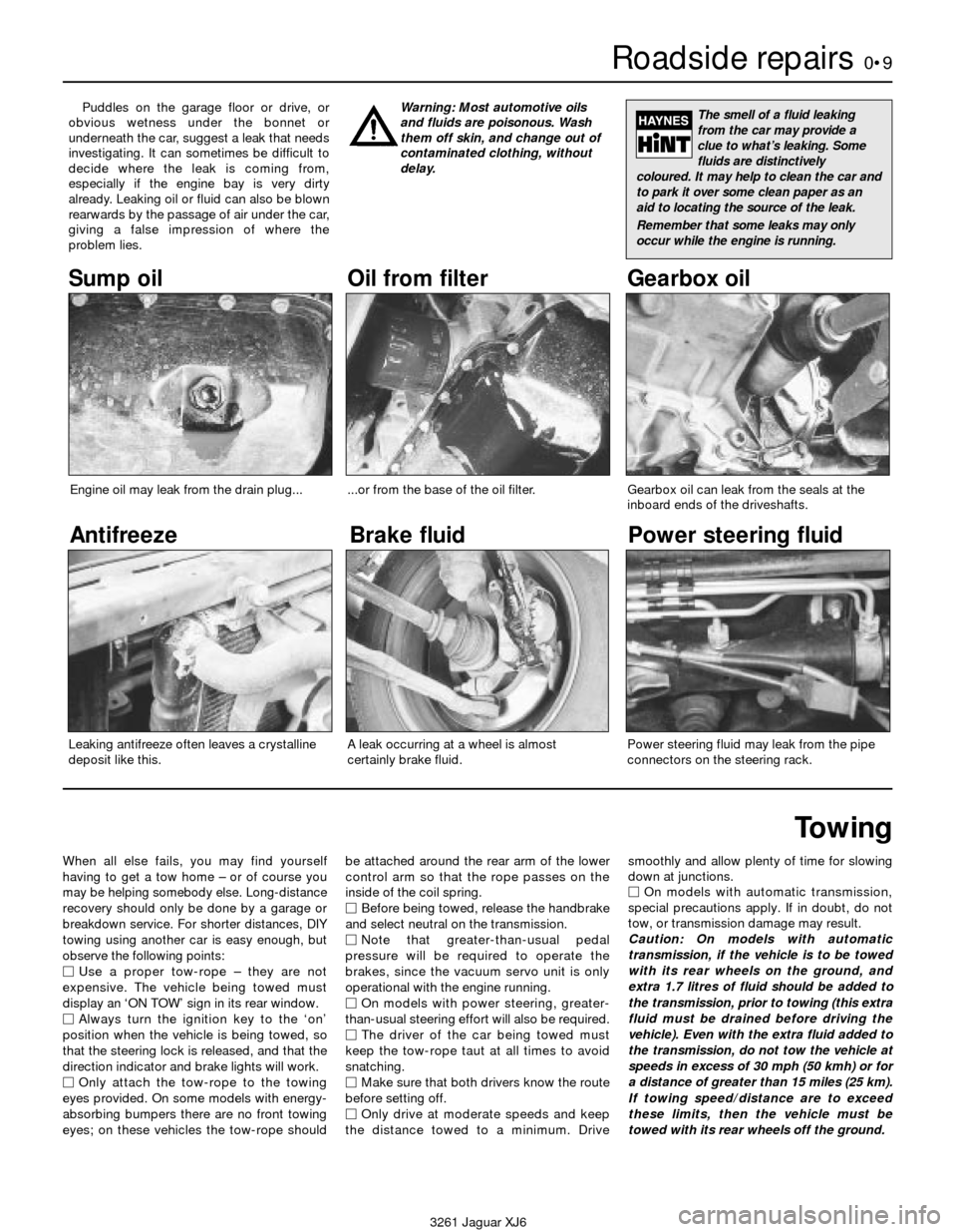
Puddles on the garage floor or drive, or
obvious wetness under the bonnet or
underneath the car, suggest a leak that needs
investigating. It can sometimes be difficult to
decide where the leak is coming from,
especially if the engine bay is very dirty
already. Leaking oil or fluid can also be blown
rearwards by the passage of air under the car,
giving a false impression of where the
problem lies.Warning: Most automotive oils
and fluids are poisonous. Wash
them off skin, and change out of
contaminated clothing, without
delay.The smell of a fluid leaking
from the car may provide a
clue to what’s leaking. Some
fluids are distinctively
coloured. It may help to clean the car and
to park it over some clean paper as an
aid to locating the source of the leak.
Remember that some leaks may only
occur while the engine is running.
Sump oil Gearbox oil
Brake fluid
Power steering fluid
Oil from filter
Antifreeze
Engine oil may leak from the drain plug......or from the base of the oil filter.
Leaking antifreeze often leaves a crystalline
deposit like this.Gearbox oil can leak from the seals at the
inboard ends of the driveshafts.
A leak occurring at a wheel is almost
certainly brake fluid.Power steering fluid may leak from the pipe
connectors on the steering rack.
Page 19 of 227
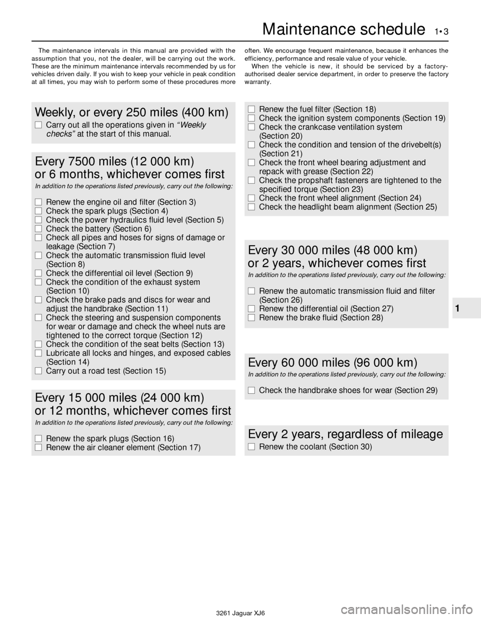
The maintenance intervals in this manual are provided with the
assumption that you, not the dealer, will be carrying out the work.
These are the minimum maintenance intervals recommended by us for
vehicles driven daily. If you wish to keep your vehicle in peak condition
at all times, you may wish to perform some of these procedures moreoften. We encourage frequent maintenance, because it enhances the
efficiency, performance and resale value of your vehicle.
When the vehicle is new, it should be serviced by a factory-
authorised dealer service department, in order to preserve the factory
warranty.
Maintenance schedule 1•3
1
3261 Jaguar XJ6
Weekly, or every 250 miles (400 km)
m mCarry out all the operations given in “Weekly
checks”at the start of this manual.
m
mRenew the fuel filter (Section 18)
m mCheck the ignition system components (Section 19)
m mCheck the crankcase ventilation system
(Section 20)
m mCheck the condition and tension of the drivebelt(s)
(Section 21)
m mCheck the front wheel bearing adjustment and
repack with grease (Section 22)
m mCheck the propshaft fasteners are tightened to the
specified torque (Section 23)
m mCheck the front wheel alignment (Section 24)
m mCheck the headlight beam alignment (Section 25)
Every 7500 miles (12 000 km)
or 6 months, whichever comes first
In addition to the operations listed previously, carry out the following:
m mRenew the engine oil and filter (Section 3)
m mCheck the spark plugs (Section 4)
m mCheck the power hydraulics fluid level (Section 5)
m mCheck the battery (Section 6)
m mCheck all pipes and hoses for signs of damage or
leakage (Section 7)
m mCheck the automatic transmission fluid level
(Section 8)
m mCheck the differential oil level (Section 9)
m mCheck the condition of the exhaust system
(Section 10)
m mCheck the brake pads and discs for wear and
adjust the handbrake (Section 11)
m mCheck the steering and suspension components
for wear or damage and check the wheel nuts are
tightened to the correct torque (Section 12)
m mCheck the condition of the seat belts (Section 13)
m mLubricate all locks and hinges, and exposed cables
(Section 14)
m mCarry out a road test (Section 15)
Every 2 years, regardless of mileage
m
mRenew the coolant (Section 30)
Every 60 000 miles (96 000 km)
In addition to the operations listed previously, carry out the following:
m
mCheck the handbrake shoes for wear (Section 29)
Every 30 000 miles (48 000 km)
or 2 years, whichever comes first
In addition to the operations listed previously, carry out the following:
m mRenew the automatic transmission fluid and filter
(Section 26)
m mRenew the differential oil (Section 27)
m mRenew the brake fluid (Section 28)
Every 15 000 miles (24 000 km)
or 12 months, whichever comes first
In addition to the operations listed previously, carry out the following:
m mRenew the spark plugs (Section 16)
m mRenew the air cleaner element (Section 17)
Page 22 of 227
1 General information
1This Chapter is designed to help the home
mechanic maintain his/her vehicle for safety,
economy, long life and peak performance.
2The Chapter contains a master
maintenance schedule, followed by Sections
dealing specifically with each task in the
schedule. Visual checks, adjustments,
component renewal and other helpful items
are included. Refer to the accompanying
illustrations of the engine compartment and
the underside of the vehicle for the locations
of the various components.
3Servicing your vehicle in accordance with
the mileage/time maintenance schedule and
the following Sections will provide a planned
maintenance programme, which should result
in a long and reliable service life. This is a
comprehensive plan, so maintaining some
items but not others at the specified service
intervals, will not produce the same results.
4As you service your vehicle, you will
discover that many of the procedures can -
and should - be grouped together, because of
the particular procedure being performed, or
because of the proximity of two otherwise-
unrelated components to one another. For
example, if the vehicle is raised for any
reason, the exhaust can be inspected at the
same time as the suspension and steering
components.
5The first step in this maintenance
programme is to prepare yourself before the
actual work begins. Read through all theSections relevant to the work to be carried out,
then make a list and gather all the parts and
tools required. If a problem is encountered,
seek advice from a parts specialist, or a dealer
service department.
2 Intensive maintenance
1If, from the time the vehicle is new, the
routine maintenance schedule is followed
closely, and frequent checks are made of fluid
levels and high-wear items, as suggested
throughout this manual, the engine will be
kept in relatively good running condition, and
the need for additional work will be minimised.
2It is possible that there will be times when
the engine is running poorly due to the lack of
regular maintenance. This is even more likely
if a used vehicle, which has not received
regular and frequent maintenance checks, is
purchased. In such cases, additional work
may need to be carried out, outside of the
regular maintenance intervals.
3If engine wear is suspected, a compression
test (refer to Chapter 2) will provide valuable
information regarding the overall performance
of the main internal components. Such a test
can be used as a basis to decide on the extent
of the work to be carried out. If, for example, a
compression test indicates serious internal
engine wear, conventional maintenance as
described in this Chapter will not greatly
improve the performance of the engine, and
may prove a waste of time and money, unless
extensive overhaul work is carried out first.4The following series of operations are those
which are most often required to improve the
performance of a generally poor-running
engine:
Primary operations
a) Clean, inspect and test the battery
(Section 6).
b) Check all the engine-related fluids (refer
to “Weekly checks”).
c) Check the condition and tension of the
auxiliary drivebelt (Section 21).
d) Renew the spark plugs (Section 16).
e) Inspect the distributor cap and rotor arm
(Section 19).
f) Check the condition of the air filter, and
renew if necessary (Section 17).
g) Renew the fuel filter (Section 18).
h) Check the condition of all hoses, and
check for fluid leaks (Section 7).
i) Check the exhaust gas emissions (see
Chapter 6).
5If the above operations do not prove fully
effective, carry out the following secondary
operations:
Secondary operations
All items listed under “Primary operations”,
plus the following:
a) Check the charging system (refer to
Chapter 5).
b) Check the ignition system (refer to
Chapter 5).
c) Check the fuel system (refer to Chapter 4).
d) Renew the distributor cap and rotor arm
(Section 19).
e) Renew the ignition HT leads (Section 19).
1•6Maintenance procedures
3261 Jaguar XJ6
Every 7500 miles (12 000 km) or 6 months
3 Engine oil and filter renewal
2
1Frequent oil changes are the best
preventive maintenance the home mechanic
can give the engine, because ageing oil
becomes diluted and contaminated, which
leads to premature engine wear.
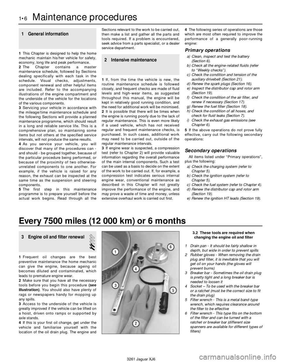
2Make sure that you have all the necessary
tools before you begin this procedure (see
illustration). You should also have plenty of
rags or newspapers handy for mopping up
any spills.
3Access to the underside of the vehicle is
greatly improved if the vehicle can be lifted on
a hoist, driven onto ramps or supported by
axle stands.
4If this is your first oil change, get under the
vehicle and familiarise yourself with the
location of the oil drain plug. The engine and
3.2 These tools are required when
changing the engine oil and filter
1 Drain pan - It should be fairly shallow in
depth, but wide in order to prevent spills
2 Rubber gloves - When removing the drain
plug and filter, it is inevitable that you will
get oil on your hands (the gloves will
prevent burns)
3 Breaker bar - Sometimes the oil drain plug
is pretty tight and a long breaker bar is
needed to loosen it
4 Socket – To be used with the breaker bar
or a ratchet (must be the correct size to fit
the drain plug)
5 Filter wrench - This is a metal band-type
wrench, which requires clearance around
the filter to be effective
6 Filter wrench - This type fits on the bottom
of the filter and can be turned with a
ratchet or breaker bar (different size
spanners are available for different types of
filters)
Page 25 of 227
5 Power hydraulic system
fluid level check
1
Caution: Use only Castrol or Jaguar
hydraulic system mineral oil (HSMO) in the
power hydraulic system (available at
Jaguar dealer service departments).
1The power hydraulic system controls the ride
levelling and the brake servo systems. The
fluid reservoir also supplies the power
steering system on some models. The level
of the fluid should be carefully maintained. Low
fluid levels can adversely affect the riding and
braking capabilities of your vehicle. The power
hydraulic system fluid reservoir is located on
the right inner wing of the engine compartment.
1988 and 1989 models
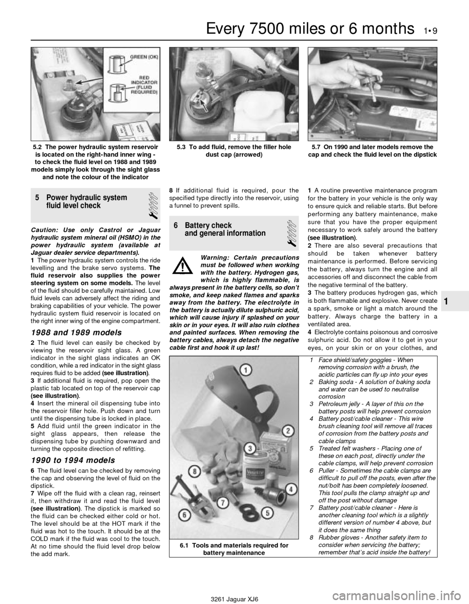
2The fluid level can easily be checked by
viewing the reservoir sight glass. A green
indicator in the sight glass indicates an OK
condition, while a red indicator in the sight glass
requires fluid to be added (see illustration).
3If additional fluid is required, pop open the
plastic tab located on top of the reservoir cap
(see illustration).
4Insert the mineral oil dispensing tube into
the reservoir filler hole. Push down and turn
until the dispensing tube is locked in place.
5Add fluid until the green indicator in the
sight glass appears, then release the
dispensing tube by pushing downward and
turning the opposite direction of refitting.
1990 to 1994 models
6The fluid level can be checked by removing
the cap and observing the level of fluid on the
dipstick.
7Wipe off the fluid with a clean rag, reinsert
it, then withdraw it and read the fluid level
(see illustration). The dipstick is marked so
the fluid can be checked either cold or hot.
The level should be at the HOT mark if the
fluid was hot to the touch. It should be at the
COLD mark if the fluid was cool to the touch.
At no time should the fluid level drop below
the add mark.8If additional fluid is required, pour the
specified type directly into the reservoir, using
a funnel to prevent spills.
6 Battery check
and general information
1
Warning: Certain precautions
must be followed when working
with the battery. Hydrogen gas,
which is highly flammable, is
always present in the battery cells, so don’t
smoke, and keep naked flames and sparks
away from the battery. The electrolyte in
the battery is actually dilute sulphuric acid,
which will cause injury if splashed on your
skin or in your eyes. It will also ruin clothes
and painted surfaces. When removing the
battery cables, always detach the negative
cable first and hook it up last!1A routine preventive maintenance program
for the battery in your vehicle is the only way
to ensure quick and reliable starts. But before
performing any battery maintenance, make
sure that you have the proper equipment
necessary to work safely around the battery
(see illustration).
2There are also several precautions that
should be taken whenever battery
maintenance is performed. Before servicing
the battery, always turn the engine and all
accessories off and disconnect the cable from
the negative terminal of the battery.
3The battery produces hydrogen gas, which
is both flammable and explosive. Never create
a spark, smoke or light a match around the
battery. Always charge the battery in a
ventilated area.
4Electrolyte contains poisonous and corrosive
sulphuric acid. Do not allow it to get in your
eyes, on your skin or on your clothes, and
Every 7500 miles or 6 months 1•9
1
5.2 The power hydraulic system reservoir
is located on the right-hand inner wing -
to check the fluid level on 1988 and 1989
models simply look through the sight glass
and note the colour of the indicator5.3 To add fluid, remove the filler hole
dust cap (arrowed)5.7 On 1990 and later models remove the
cap and check the fluid level on the dipstick
6.1 Tools and materials required for
battery maintenance
1 Face shield/safety goggles - When
removing corrosion with a brush, the
acidic particles can fly up into your eyes
2 Baking soda - A solution of baking soda
and water can be used to neutralise
corrosion
3 Petroleum jelly - A layer of this on the
battery posts will help prevent corrosion
4 Battery post/cable cleaner - This wire
brush cleaning tool will remove all traces
of corrosion from the battery posts and
cable clamps
5 Treated felt washers - Placing one of
these on each post, directly under the
cable clamps, will help prevent corrosion
6 Puller - Sometimes the cable clamps are
difficult to pull off the posts, even after the
nut/bolt has been completely loosened.
This tool pulls the clamp straight up and
off the post without damage
7 Battery post/cable cleaner - Here is
another cleaning tool which is a slightly
different version of number 4 above, but
it does the same thing
8 Rubber gloves - Another safety item to
consider when servicing the battery;
remember that’s acid inside the battery!
3261 Jaguar XJ6
Page 28 of 227
silencer and catalytic converter. If the
components can come in contact with the
body or suspension parts, secure the exhaust
system with new mounts.
5Check the running condition of the engine
by inspecting inside the end of the tailpipe.
The exhaust deposits here are an indication of
engine state-of-tune. If the pipe is black and
sooty or coated with white deposits, the
engine is in need of a tune-up, including a
thorough fuel system inspection.
11 Braking system - general
check and adjustment
2
Warning: The dust created by
the brake system may contain
asbestos, which is harmful to
your health. Never blow it out
with compressed air and don’t inhale any
of it. An approved filtering mask should be
worn when working on the brakes. Do not,
under any circumstances, use petroleum-
based solvents to clean brake parts. Use
brake system cleaner only! Try to use non-
asbestos replacement parts whenever
possible.
Note: For detailed photographs of the brake
system, refer to Chapter 9.
1In addition to the specified intervals, the
brakes should be inspected every time the
wheels are removed or whenever a defect is
suspected. Any of the following symptoms
could indicate a potential brake system
defect: The vehicle pulls to one side when the
brake pedal is depressed; the brakes make
squealing or dragging noises when applied;
brake pedal travel is excessive; the pedal
pulsates; brake fluid leaks, usually onto the
inside of the tyre or wheel.
2The disc brakes have built-in electrical wear
indicators which cause a warning lamp to
illuminate on the instrument panel when
they’re worn to the renewal point. When the
warning light comes on, replace the pads
immediately or expensive damage to the
discs can result.
3Loosen the wheel nuts.
4Raise the vehicle and place it securely on
axle stands.
5Remove the wheels.
Disc brakes
6There are two pads (an outer and an inner)
in each caliper. The pads are visible through
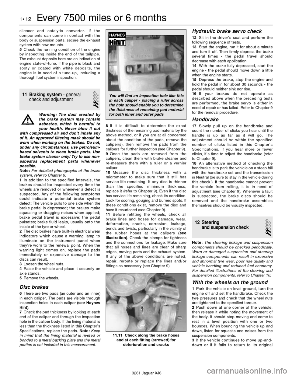
inspection holes in each caliper (see Haynes
Hint).
7Check the pad thickness by looking at each
end of the caliper and through the inspection
hole in the caliper body. If the lining material is
less than the thickness listed in this Chapter’s
Specifications, replace the pads. Note:Keep
in mind that the lining material is riveted or
bonded to a metal backing plate and the metal
portion is not included in this measurement.8If it is difficult to determine the exact
thickness of the remaining pad material by the
above method, or if you are at all concerned
about the condition of the pads, remove the
caliper(s), then remove the pads from the
calipers for further inspection (see Chapter 9).
9Once the pads are removed from the
calipers, clean them with brake cleaner and
re-measure them with a ruler or a vernier
caliper.
10Measure the disc thickness with a
micrometer to make sure that it still has
service life remaining. If any disc is thinner
than the specified minimum thickness,
replace it (refer to Chapter 9). Even if the disc
has service life remaining, check its condition.
Look for scoring, gouging and burned spots. If
these conditions exist, remove the disc and
have it resurfaced (see Chapter 9).
11Before refitting the wheels, check all
brake lines and hoses for damage, wear,
deformation, cracks, corrosion, leakage,
bends and twists, particularly in the vicinity of
the rubber hoses at the calipers (see
illustration). Check the clamps for tightness
and the connections for leakage. Make sure
that all hoses and lines are clear of sharp
edges, moving parts and the exhaust system.
If any of the above conditions are noted,
repair, reroute or replace the lines and/or
fittings as necessary (see Chapter 9).
Hydraulic brake servo check
12Sit in the driver’s seat and perform the
following sequence of tests.
13Start the engine, run it for about a minute
and turn it off. Then firmly depress the brake
several times - the pedal travel should
decrease with each application.
14With the brake fully depressed, start the
engine - the pedal should move down a little
when the engine starts.
15Depress the brake, stop the engine and
hold the pedal in for about 30 seconds - the
pedal should neither sink nor rise.
16If your brakes do not operate as
described above when the preceding tests
are performed, the brake servo is either in
need of repair or has failed. Refer to Chapter 9
for the removal procedure.
Handbrake
17Slowly pull up on the handbrake and
count the number of clicks you hear until the
handle is up as far as it will go. The
adjustment should be within the specified
number of clicks listed in this Chapter’s
Specifications. If you hear more or fewer
clicks, it’s time to adjust the handbrake (refer
to Chapter 9).
18An alternative method of checking the
handbrake is to park the vehicle on a steep hill
with the handbrake set and the transmission
in Neutral (be sure to stay in the vehicle during
this check!). If the handbrake cannot prevent
the vehicle from rolling, it is in need of
adjustment (see Chapter 9). Whenever a fault
is suspected, the brake discs should be
removed and the handbrake assemblies
themselves should be visually inspected.
12 Steering
and suspension check
2
Note: The steering linkage and suspension
components should be checked periodically.
Worn or damaged suspension and steering
linkage components can result in excessive
and abnormal tyre wear, poor ride quality and
vehicle handling and reduced fuel economy.
For detailed illustrations of the steering and
suspension components, refer to Chapter 10.
With the wheels on the ground
1Park the vehicle on level ground, turn the
engine off and set the handbrake. Check the
tyre pressures and check that the wheel nuts
are tightened to the specified torque.
2Push down at one corner of the vehicle,
then release it while noting the movement of
the body. It should stop moving and come to
rest in a level position with one or two
bounces. When bouncing the vehicle up and
down, listen for squeaks and noises from the
suspension components.
3If the vehicle continues to move up-and-
down or if it fails to return to its original
1•12Every 7500 miles or 6 months
11.11 Check along the brake hoses
and at each fitting (arrowed) for
deterioration and cracks
3261 Jaguar XJ6
You will find an inspection hole like this
in each caliper - placing a ruler across
the hole should enable you to determine
the thickness of remaining pad material
for both inner and outer pads
Page 29 of 227
position, a worn or weak shock absorber is
probably the reason.
4Repeat the above check at each of the
three remaining corners of the vehicle.
Under the vehicle
5Raise the vehicle with a trolley jack and
support it securely on axle stands. See
“Jacking and towing”for proper jacking
points.
6Check the shock absorbers for evidence of
fluid leakage. Make sure that any fluid noted is
from the shocks and not from any other
source. Also check the rubber mounts at each
end for deterioration If the shock absorbers
fail any of the tests above replace the shocks
as a set.
7Check the tyres for irregular wear patterns
and proper inflation. See “Weekly checks”for
information regarding tyre wear.
8Inspect the universal joint between the
steering shaft and the steering gear housing.
Check the steering gear housing for grease
leakage. Make sure that the dust seals and
boots are not damaged and that the boot
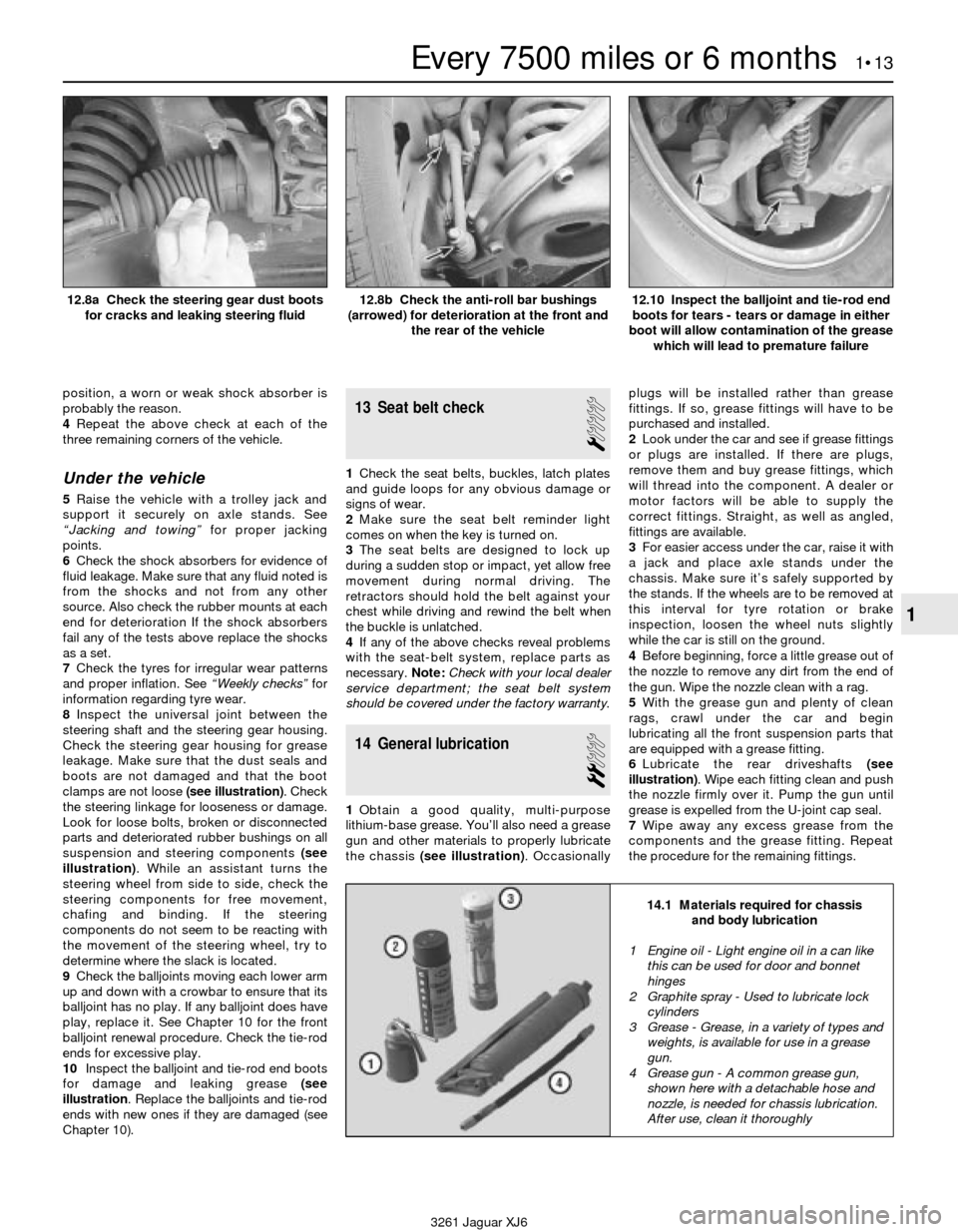
clamps are not loose (see illustration). Check
the steering linkage for looseness or damage.
Look for loose bolts, broken or disconnected
parts and deteriorated rubber bushings on all
suspension and steering components (see
illustration). While an assistant turns the
steering wheel from side to side, check the
steering components for free movement,
chafing and binding. If the steering
components do not seem to be reacting with
the movement of the steering wheel, try to
determine where the slack is located.
9Check the balljoints moving each lower arm
up and down with a crowbar to ensure that its
balljoint has no play. If any balljoint does have
play, replace it. See Chapter 10 for the front
balljoint renewal procedure. Check the tie-rod
ends for excessive play.
10Inspect the balljoint and tie-rod end boots
for damage and leaking grease (see
illustration. Replace the balljoints and tie-rod
ends with new ones if they are damaged (see
Chapter 10).
13 Seat belt check
1
1Check the seat belts, buckles, latch plates
and guide loops for any obvious damage or
signs of wear.
2Make sure the seat belt reminder light
comes on when the key is turned on.
3The seat belts are designed to lock up
during a sudden stop or impact, yet allow free
movement during normal driving. The
retractors should hold the belt against your
chest while driving and rewind the belt when
the buckle is unlatched.
4If any of the above checks reveal problems
with the seat-belt system, replace parts as
necessary.Note:Check with your local dealer
service department; the seat belt system
should be covered under the factory warranty.
14 General lubrication
2
1Obtain a good quality, multi-purpose
lithium-base grease. You’ll also need a grease
gun and other materials to properly lubricate
the chassis (see illustration). Occasionallyplugs will be installed rather than grease
fittings. If so, grease fittings will have to be
purchased and installed.
2Look under the car and see if grease fittings
or plugs are installed. If there are plugs,
remove them and buy grease fittings, which
will thread into the component. A dealer or
motor factors will be able to supply the
correct fittings. Straight, as well as angled,
fittings are available.
3For easier access under the car, raise it with
a jack and place axle stands under the
chassis. Make sure it’s safely supported by
the stands. If the wheels are to be removed at
this interval for tyre rotation or brake
inspection, loosen the wheel nuts slightly
while the car is still on the ground.
4Before beginning, force a little grease out of
the nozzle to remove any dirt from the end of
the gun. Wipe the nozzle clean with a rag.
5With the grease gun and plenty of clean
rags, crawl under the car and begin
lubricating all the front suspension parts that
are equipped with a grease fitting.
6Lubricate the rear driveshafts (see
illustration). Wipe each fitting clean and push
the nozzle firmly over it. Pump the gun until
grease is expelled from the U-joint cap seal.
7Wipe away any excess grease from the
components and the grease fitting. Repeat
the procedure for the remaining fittings.
Every 7500 miles or 6 months 1•13
1
14.1 Materials required for chassis
and body lubrication
3261 Jaguar XJ6 12.8a Check the steering gear dust boots
for cracks and leaking steering fluid
12.8b Check the anti-roll bar bushings
(arrowed) for deterioration at the front and
the rear of the vehicle12.10 Inspect the balljoint and tie-rod end
boots for tears - tears or damage in either
boot will allow contamination of the grease
which will lead to premature failure
1 Engine oil - Light engine oil in a can like
this can be used for door and bonnet
hinges
2 Graphite spray - Used to lubricate lock
cylinders
3 Grease - Grease, in a variety of types and
weights, is available for use in a grease
gun.
4 Grease gun - A common grease gun,
shown here with a detachable hose and
nozzle, is needed for chassis lubrication.
After use, clean it thoroughly
Page 36 of 227
30 Coolant renewal
2
Warning: Do not allow engine
coolant (antifreeze) to come in
contact with your skin or painted
surfaces of the vehicle. Rinse off
spills immediately with plenty of water.
Antifreeze is highly toxic if ingested. Never
leave antifreeze laying around in an open
container or in puddles on the floor;
children and pets are attracted by it’s
sweet smell and may drink it. Check with
local authorities about disposing of used
antifreeze. Your local authority may have
collection centres which will see that
antifreeze is disposed of safely.1Periodically, the cooling system should be
drained, flushed and refilled to replenish the
antifreeze mixture and prevent formation of
rust and corrosion, which can impair the
performance of the cooling system and
cause engine damage. When the cooling
system is serviced, all hoses and the radiator
cap should be checked and renewed if
necessary.
Draining
2Apply the handbrake and block the wheels.
If the vehicle has just been driven, wait several
hours to allow the engine to cool down before
beginning this procedure.
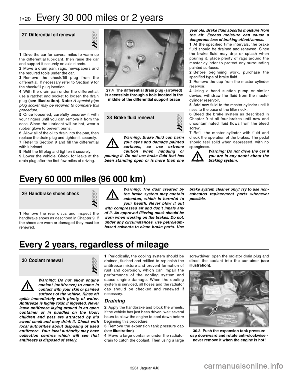
3Remove the expansion tank pressure cap
(see illustration).
4Move a large container under the radiator
drain to catch the coolant. Then using a largescrewdriver, open the radiator drain plug and
direct the coolant into the container (see
illustration).
27 Differential oil renewal
2
1Drive the car for several miles to warm up
the differential lubricant, then raise the car
and support it securely on axle stands.
2Move a drain pan, rags, newspapers and
the required tools under the car.
3Remove the check/fill plug from the
differential. If necessary refer to Section 9 for
the check/fill plug location.
4With the drain pan under the differential,
use a ratchet and socket to loosen the drain
plug (see illustration). Note:A special pipe
plug socket may be required to complete this
procedure.
5Once loosened, carefully unscrew it with
your fingers until you can remove it from the
case. Since the lubricant will be hot, wear a
rubber glove to prevent burns.
6Allow all of the oil to drain into the pan, then
replace the drain plug and tighten it securely.
7Refer to Section 9 and fill the differential
with lubricant.
8Refit the fill plug and tighten it securely.
9Lower the vehicle. Check for leaks at the
drain plug after the first few miles of driving.
28 Brake fluid renewal
2
Warning: Brake fluid can harm
your eyes and damage painted
surfaces, so use extreme
caution when handling or
pouring it. Do not use brake fluid that has
been standing open or is more than oneyear old. Brake fluid absorbs moisture from
the air. Excess moisture can cause a
dangerous loss of braking effectiveness.
1At the specified time intervals, the brake
fluid should be drained and renewed. Since
the brake fluid may drip or splash when
pouring it, place plenty of rags around the
master cylinder to protect any surrounding
painted surfaces.
2Before beginning work, purchase the
specified type of brake fluid.
3Remove the cap from the master cylinder
reservoir.
4Using a hand suction pump or similar
device, withdraw the fluid from the master
cylinder reservoir.
5Add new fluid to the master cylinder until it
rises to the base of the filler neck.
6Bleed the brake system as described in
Chapter 9 at all four brakes until new and
uncontaminated fluid flows from the bleed
screw.
7Refill the master cylinder with fluid and
check the operation of the brakes. The pedal
should feel solid when depressed, with no
sponginess.
Warning: Do not drive the car if
you are in any doubt about the
braking system.
1•20Every 30 000 miles or 2 years
27.4 The differential drain plug (arrowed)
is accessible through a hole located in the
middle of the differential support brace
30.3 Push the expansion tank pressure
cap downward and rotate anti-clockwise -
never remove it when the engine is hot!
3261 Jaguar XJ6
Every 60 000 miles (96 000 km)
29 Handbrake shoes check
2
1Remove the rear discs and inspect the
handbrake shoes as described in Chapter 9. If
the shoes are worn or damaged they must be
renewed.Warning: The dust created by
the brake system may contain
asbestos, which is harmful to
your health. Never blow it out
with compressed air and don’t inhale any
of it. An approved filtering mask should be
worn when working on the brakes. Do not,
under any circumstances, use petroleum-
based solvents to clean brake parts. Usebrake system cleaner only! Try to use non-
asbestos replacement parts whenever
possible.
Every 2 years, regardless of mileage
Page 57 of 227
Engine block
Deck warpage limit . . . . . . . . . . . . . . . . . . . . . . . . . . . . . . . . . . . . . . . . . 0.076 mm (0.003 inch)
Cylinder bore diameter
Standard
Size group A . . . . . . . . . . . . . . . . . . . . . . . . . . . . . . . . . . . . . . . . . . 90.990 to 91.003 mm (3.5823 to 3.5828 inches)
Size group B . . . . . . . . . . . . . . . . . . . . . . . . . . . . . . . . . . . . . . . . . . 91.005 to 91.018 mm (3.5829 to 3.5834 inches)
Oversize
0.25 mm (0.010 inch) OS . . . . . . . . . . . . . . . . . . . . . . . . . . . . . . . . 91.259 to 91.272 mm (3.5929 to 3.5934 inches)
0.50 mm (0.020 inch) OS . . . . . . . . . . . . . . . . . . . . . . . . . . . . . . . . 91.513 to 91.526 mm (3.6029 to 3.6034 inches)
Pistons and rings
Piston-to-bore clearance . . . . . . . . . . . . . . . . . . . . . . . . . . . . . . . . . . . . 0.017 to 0.043 mm (0.0007 to 0.0017 inch)
Piston ring end gap
No.1 (top) compression ring . . . . . . . . . . . . . . . . . . . . . . . . . . . . . . . . 0.40 to 0.66 mm (0.016 to 0.026 inch)
No.2 (middle) compression ring . . . . . . . . . . . . . . . . . . . . . . . . . . . . . 0.40 to 0.66 mm (0.016 to 0.026 inch)
Oil ring . . . . . . . . . . . . . . . . . . . . . . . . . . . . . . . . . . . . . . . . . . . . . . . . . 0.30 to 0.55 mm (0.012 to 0.022 inch)
Piston ring groove clearance
No. 1 (top) compression ring . . . . . . . . . . . . . . . . . . . . . . . . . . . . . . . 0.040 to 0.076 mm (0.0016 to 0.0030 inch)
No. 2 (middle) compression ring . . . . . . . . . . . . . . . . . . . . . . . . . . . . . 0.040 to 0.076 mm (0.0016 to 0.0030 inch)
Torque wrench settingsNm lbf ft
Main bearing cap bolts . . . . . . . . . . . . . . . . . . . . . . . . . . . . . . . . . . . . . . 136 to 142 100 to 105
Connecting rod cap nuts . . . . . . . . . . . . . . . . . . . . . . . . . . . . . . . . . . . . 50 to 60 37 to 44
* Note:Refer to Part A for additional torque specifications.
2B•2 Engine removal and overhaul procedures
3261 Jaguar XJ6
1 General information
Included in this portion of Chapter 2 are the
general overhaul procedures for the cylinder
head and internal engine components.
The information ranges from advice
concerning preparation for an overhaul and
the purchase of replacement parts to detailed,
step-by-step procedures covering removal
and refitting of internal engine components
and the inspection of parts.
The following Sections have been written
based on the assumption that the engine has
been removed from the vehicle. For
information concerning in-vehicle engine
repair, as well as removal and refitting of the
external components necessary for the
overhaul, see Part A of this Chapter.
The Specifications included in this Part are
only those necessary for the inspection and
overhaul procedures which follow. Refer to
Part A for additional Specifications.
2 Engine overhaul-
general information
It’s not always easy to determine when, or if,
an engine should be completely overhauled,
as a number of factors must be considered.
High mileage is not necessarily an indication
that an overhaul is needed, while low mileage
doesn’t preclude the need for an overhaul.
Frequency of servicing is probably the most
important consideration. An engine that’s had
regular and frequent oil and filter changes, as
well as other required maintenance, will most
likely give many thousands of miles of reliableservice. Conversely, a neglected engine may
require an overhaul very early in its life.
Excessive oil consumption is an indication
that piston rings, valve seals and/or valve
guides are in need of attention. Make sure that
oil leaks aren’t responsible before deciding
that the rings and/or guides are bad. Perform a
cylinder compression check to determine the
extent of the work required (see Section 4).
Also check the vacuum readings under various
conditions (see Section 3).
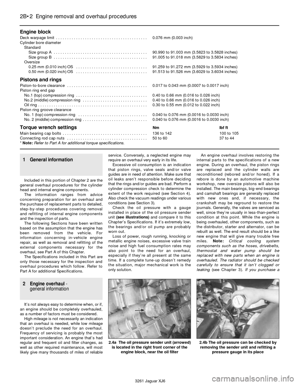
Check the oil pressure with a gauge
installed in place of the oil pressure sender
unit (see illustrations)and compare it to this
Chapter’s Specifications. If it’s extremely low,
the bearings and/or oil pump are probably
worn out.
Loss of power, rough running, knocking or
metallic engine noises, excessive valve train
noise and high fuel consumption rates may
also point to the need for an overhaul,
especially if they’re all present at the same
time. If a complete tune-up doesn’t remedy
the situation, major mechanical work is the
only solution.An engine overhaul involves restoring the
internal parts to the specifications of a new
engine. During an overhaul, the piston rings
are replaced and the cylinder walls are
reconditioned (rebored and/or honed). If a
rebore is done by an automotive machine
workshop, new oversize pistons will also be
installed. The main bearings, big-end bearings
and camshaft bearings are generally replaced
with new ones and, if necessary, the
crankshaft may be reground to restore the
journals. Generally, the valves are serviced as
well, since they’re usually in less-than-perfect
condition at this point. While the engine is
being overhauled, other components, such as
the distributor, starter and alternator, can be
rebuilt as well. The end result should be a like
new engine that will give many trouble free
miles. Note:Critical cooling system
components such as the hoses, drivebelts,
thermostat and water pump should be
replaced with new parts when an engine is
overhauled. The radiator should be checked
carefully to ensure that it isn’t clogged or
leaking (see Chapter 3).If you purchase a
2.4a The oil pressure sender unit (arrowed)
is located in the right front corner of the
engine block, near the oil filter2.4b The oil pressure can be checked by
removing the sender unit and refitting a
pressure gauge in its place
Page 58 of 227
rebuilt engine or short block, some rebuilders
will not warranty their engines unless the
radiator has been professionally flushed. Also,
we don’t recommend overhauling the oil
pump - always refit a new one when an engine
is rebuilt.
Before beginning the engine overhaul, read
through the entire procedure to familiarise
yourself with the scope and requirements of
the job. Overhauling an engine isn’t difficult,
but it is time-consuming. Plan on the vehicle
being tied up for a minimum of two weeks,
especially if parts must be taken to an
automotive machine workshop for repair or
reconditioning. Check on availability of parts
and make sure that any necessary special
tools and equipment are obtained in advance.
Most work can be done with typical hand
tools, although a number of precision
measuring tools are required for inspecting
parts to determine if they must be renewed.
Often an automotive machine workshop will
handle the inspection of parts and offer
advice concerning reconditioning and
renewal. Note:Always wait until the engine
has been completely dismantled and all
components, especially the engine block,
have been inspected before deciding what
service and repair operations must be
performed by an automotive machine
workshop. Since the engine block’s condition
will be the major factor to consider when
determining whether to overhaul the original
engine or buy a rebuilt one, never purchase
parts or have machine work done on other
components until the engine block has been
thoroughly inspected. As a general rule, time
is the primary cost of an overhaul, so it
doesn’t pay to refit worn or substandard
parts.
If it turns out that a number of major
components are beyond reconditioning, it
may be cost effective to buy a factory-rebuilt
engine from a Jaguar dealership.
As a final note, to ensure maximum life and
minimum trouble from a rebuilt engine,
everything must be assembled with care in a
spotlessly-clean environment.
3 Vacuum gauge
diagnostic checks
2
A vacuum gauge provides valuable
information about what is going on in the
engine at a low cost. You can check for worn
rings or cylinder walls, leaking cylinder head or
intake manifold gaskets, incorrect carburettor
adjustments, restricted exhaust, stuck or
burned valves, weak valve springs, improper
ignition or valve timing and ignition problems.
Unfortunately, vacuum gauge readings are
easy to misinterpret, so they should be used
with other tests to confirm the diagnosis.
Both the absolute readings and the rate of
needle movement are important for accurate
interpretation. Most gauges measure vacuumin inches of mercury (in-Hg). As vacuum
increases (or atmospheric pressure decreases),
the reading will decrease. Also, for every
1000 foot increase in elevation above sea level;
the gauge readings will decrease about one
inch of mercury.
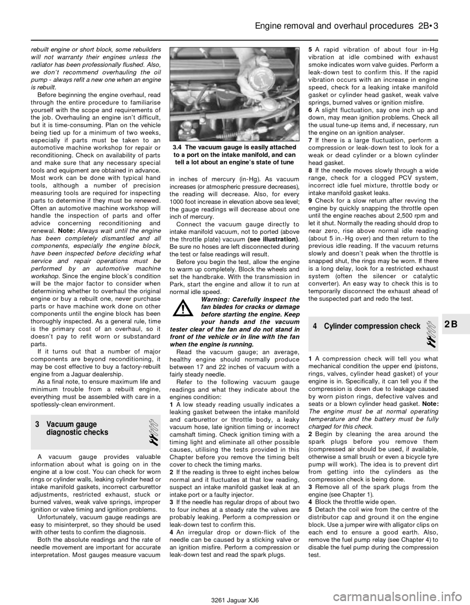
Connect the vacuum gauge directly to
intake manifold vacuum, not to ported (above
the throttle plate) vacuum (see illustration).
Be sure no hoses are left disconnected during
the test or false readings will result.
Before you begin the test, allow the engine
to warm up completely. Block the wheels and
set the handbrake. With the transmission in
Park, start the engine and allow it to run at
normal idle speed.
Warning: Carefully inspect the
fan blades for cracks or damage
before starting the engine. Keep
your hands and the vacuum
tester clear of the fan and do not stand in
front of the vehicle or in line with the fan
when the engine is running.
Read the vacuum gauge; an average,
healthy engine should normally produce
between 17 and 22 inches of vacuum with a
fairly steady needle.
Refer to the following vacuum gauge
readings and what they indicate about the
engines condition:
1A low steady reading usually indicates a
leaking gasket between the intake manifold
and carburettor or throttle body, a leaky
vacuum hose, late ignition timing or incorrect
camshaft timing. Check ignition timing with a
timing light and eliminate all other possible
causes, utilising the tests provided in this
Chapter before you remove the timing belt
cover to check the timing marks.
2If the reading is three to eight inches below
normal and it fluctuates at that low reading,
suspect an intake manifold gasket leak at an
intake port or a faulty injector.
3If the needle has regular drops of about two
to four inches at a steady rate the valves are
probably leaking. Perform a compression or
leak-down test to confirm this.
4An irregular drop or down-flick of the
needle can be caused by a sticking valve or
an ignition misfire. Perform a compression or
leak-down test and read the spark plugs.5A rapid vibration of about four in-Hg
vibration at idle combined with exhaust
smoke indicates worn valve guides. Perform a
leak-down test to confirm this. If the rapid
vibration occurs with an increase in engine
speed, check for a leaking intake manifold
gasket or cylinder head gasket, weak valve
springs, burned valves or ignition misfire.
6A slight fluctuation, say one inch up and
down, may mean ignition problems. Check all
the usual tune-up items and, if necessary, run
the engine on an ignition analyser.
7If there is a large fluctuation, perform a
compression or leak-down test to look for a
weak or dead cylinder or a blown cylinder
head gasket.
8If the needle moves slowly through a wide
range, check for a clogged PCV system,
incorrect idle fuel mixture, throttle body or
intake manifold gasket leaks.
9Check for a slow return after revving the
engine by quickly snapping the throttle open
until the engine reaches about 2,500 rpm and
let it shut. Normally the reading should drop to
near zero, rise above normal idle reading
(about 5 in.-Hg over) and then return to the
previous idle reading. If the vacuum returns
slowly and doesn’t peak when the throttle is
snapped shut, the rings may be worn. If there
is a long delay, look for a restricted exhaust
system (often the silencer or catalytic
converter). An easy way to check this is to
temporarily disconnect the exhaust ahead of
the suspected part and redo the test.
4 Cylinder compression check
2
1A compression check will tell you what
mechanical condition the upper end (pistons,
rings, valves, cylinder head gasket) of your
engine is in. Specifically, it can tell you if the
compression is down due to leakage caused
by worn piston rings, defective valves and
seats or a blown cylinder head gasket. Note:
The engine must be at normal operating
temperature and the battery must be fully
charged for this check.
2Begin by cleaning the area around the
spark plugs before you remove them
(compressed air should be used, if available,
otherwise a small brush or even a bicycle tyre
pump will work). The idea is to prevent dirt
from getting into the cylinders as the
compression check is being done.
3Remove all of the spark plugs from the
engine (see Chapter 1).
4Block the throttle wide open.
5Detach the coil wire from the centre of the
distributor cap and ground it on the engine
block. Use a jumper wire with alligator clips on
each end to ensure a good earth. Also,
remove the fuel pump relay (see Chapter 4) to
disable the fuel pump during the compression
test.
Engine removal and overhaul procedures 2B•3
2B
3.4 The vacuum gauge is easily attached
to a port on the intake manifold, and can
tell a lot about an engine’s state of tune
3261 Jaguar XJ6