torque JAGUAR XJ6 1997 2.G Workshop Manual
[x] Cancel search | Manufacturer: JAGUAR, Model Year: 1997, Model line: XJ6, Model: JAGUAR XJ6 1997 2.GPages: 227, PDF Size: 7.2 MB
Page 4 of 227
These models are equipped with dual overhead cam in-line six-
cylinder engines. The engines feature a computer-controlled ignition
system and electronic fuel injection. Transmissions are a four-speed
automatic equipped with a lock-up torque converter. The transmission
is mounted to the back of the engine, and power is transmitted to the
fully independent rear axle through a two-piece propshaft. The
differential is bolted solidly to a frame crossmember and drives the
wheels through driveshafts equipped with inner and outer U-joints.
The front suspension is fitted with upper and lower control arms, coil
springs and shock absorbers. The rear suspension is an independent
type suspension which also have coil spring/shock absorber
assemblies and a lower control arm. The rear driveshaft acts as the
upper control arm.
Power-assisted Anti-lock Brake Systems (ABS) with four-wheel disc
brakes are standard equipment on all Jaguar XJ6 models covered in
this manual. Power rack-and-pinion steering is also standard
equipment.
Your Jaguar manual
The aim of this manual is to help you get the best value from your
vehicle. It can do so in several ways. It can help you decide what work
must be done (even should you choose to get it done by a garage). It
will also provide information on routine maintenance and servicing, and
give a logical course of action and diagnosis when random faults
occur. However, it is hoped that you will use the manual by tackling the
work yourself. On simpler jobs it may even be quicker than booking the
car into a garage and going there twice, to leave and collect it. Perhaps
most important, a lot of money can be saved by avoiding the costs a
garage must charge to cover its labour and overheads.
The manual has drawings and descriptions to show the function of
the various components so that their layout can be understood. Tasks
are described and photographed in a clear step-by-step sequence.
Notes for UK readers
Because this manual was originally written in the US, its layout
differs from our UK-originated manuals. The preliminary and reference
sections have been re-written specifically for the UK market, and the
maintenance schedule has been amended to suit UK vehicles.
However, it will be noticed that some references to componentsremain in the US style; the UK equivalent of US components and
various other US words is given in the Section headed “Use of
English”. It should be remembered that the project vehicle used in the
main Chapters of this manual was a left-hand drive US model;
therefore, the position of the steering wheel, steering column and
pedals, etc. will be on the opposite side of the vehicle on UK models.
References to “right” and “left” will need to be considered carefully to
decide which applies to UK models (eg the headlight dipped beams
should be adjusted to dip to the left of the headlight vertical line
described in Chapter 12, instead of to the right on US models). In other
instances, no reference is made to the location of a particular item, but
that item may be located on the opposite side of the vehicle on UK
models. Reference to the underbonnet photos at the start of Chapter 1
will give the reader the location of the engine compartment
components on UK models.
All specifications in the main Chapters of the manual appear in
Imperial form; the equivalent metric values can be calculated using the
“Conversion factors”page.
The only other major difference between UK and US models is in the
level of emission control equipment fitted to the vehicle. To meet the
strict emission standards present in the US, all vehicles for that market
are fitted with various emission control systems (see Chapter 6), most
of which are not fitted to the corresponding UK model, especially so on
early models. Therefore, a lot of the information contained in Chapter 6
is not applicable to UK models.
Acknowledgements
Thanks are due to Jean Preis, Rich Wilson and Ray Marcuse of
Silver Star Jaguar (Thousand Oaks, CA), Rick Calaci of Conejo Imports
(Newbury Park, CA) and Jim Strohmeier and Jonathan Lund of British
Motor Cars (Thousand Oaks, CA), for providing valuable technical
information. Technical writers who contributed to this project include
Jeff Kibler, Robert Maddox and Jay Storer.
We take great pride in the accuracy of information given in this
manual, but vehicle manufacturers make alterations and design
changes during the production run of a particular vehicle of which
they do not inform us. No liability can be accepted by the authors
or publishers for loss, damage or injury caused by any errors in, or
omissions from, the information given.
0•4Introduction
3261 Jaguar XJ6
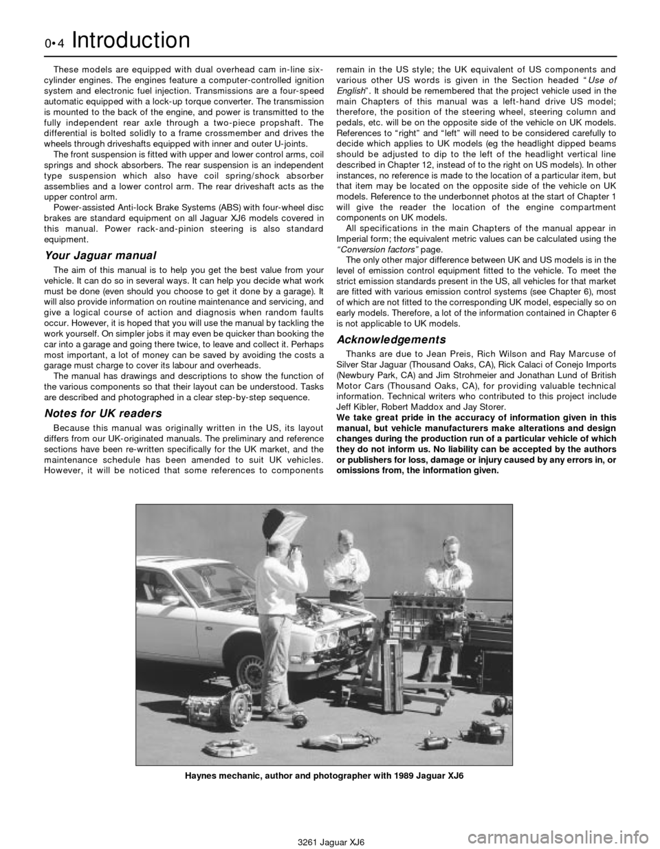
Haynes mechanic, author and photographer with 1989 Jaguar XJ6
Page 5 of 227
3261 Jaguar XJ6
Safety first!0•5
Working on your car can be dangerous.
This page shows just some of the potential
risks and hazards, with the aim of creating a
safety-conscious attitude.
General hazards
Scalding
• Don’t remove the radiator or expansion
tank cap while the engine is hot.
• Engine oil, automatic transmission fluid or
power steering fluid may also be dangerously
hot if the engine has recently been running.
Burning
• Beware of burns from the exhaust system
and from any part of the engine. Brake discs
and drums can also be extremely hot
immediately after use.
Crushing
• When working under or near
a raised vehicle,
always
supplement the
jack with axle
stands, or use
drive-on
ramps.
Never
venture
under a car which
is only supported by a jack.
• Take care if loosening or tightening high-
torque nuts when the vehicle is on stands.
Initial loosening and final tightening should
be done with the wheels on the ground.
Fire
• Fuel is highly flammable; fuel vapour is
explosive.
• Don’t let fuel spill onto a hot engine.
• Do not smoke or allow naked lights
(including pilot lights) anywhere near a
vehicle being worked on. Also beware of
creating sparks
(electrically or by use of tools).
• Fuel vapour is heavier than air, so don’t
work on the fuel system with the vehicle over
an inspection pit.
• Another cause of fire is an electrical
overload or short-circuit. Take care when
repairing or modifying the vehicle wiring.
• Keep a fire extinguisher handy, of a type
suitable for use on fuel and electrical fires.
Electric shock
• Ignition HT
voltage can be
dangerous,
especially to
people with heart
problems or a
pacemaker. Don’t
work on or near the
ignition system with
the engine running or
the ignition switched on.• Mains voltage is also dangerous. Make
sure that any mains-operated equipment is
correctly earthed. Mains power points should
be protected by a residual current device
(RCD) circuit breaker.
Fume or gas intoxication
• Exhaust fumes are
poisonous; they often
contain carbon
monoxide, which is
rapidly fatal if inhaled.
Never run the
engine in a
confined space
such as a garage
with the doors shut.
• Fuel vapour is also
poisonous, as are the vapours from some
cleaning solvents and paint thinners.
Poisonous or irritant substances
• Avoid skin contact with battery acid and
with any fuel, fluid or lubricant, especially
antifreeze, brake hydraulic fluid and Diesel
fuel. Don’t syphon them by mouth. If such a
substance is swallowed or gets into the eyes,
seek medical advice.
• Prolonged contact with used engine oil can
cause skin cancer. Wear gloves or use a
barrier cream if necessary. Change out of oil-
soaked clothes and do not keep oily rags in
your pocket.
• Air conditioning refrigerant forms a
poisonous gas if exposed to a naked flame
(including a cigarette). It can also cause skin
burns on contact.
Asbestos
• Asbestos dust can cause cancer if inhaled
or swallowed. Asbestos may be found in
gaskets and in brake and clutch linings.
When dealing with such components it is
safest to assume that they contain asbestos.
Special hazards
Hydrofluoric acid
• This extremely corrosive acid is formed
when certain types of synthetic rubber, found
in some O-rings, oil seals, fuel hoses etc, are
exposed to temperatures above 400
0C. The
rubber changes into a charred or sticky
substance containing the acid. Once formed,
the acid remains dangerous for years. If it
gets onto the skin, it may be necessary to
amputate the limb concerned.
• When dealing with a vehicle which has
suffered a fire, or with components salvaged
from such a vehicle, wear protective gloves
and discard them after use.
The battery
• Batteries contain sulphuric acid, which
attacks clothing, eyes and skin. Take care
when topping-up or carrying the battery.
• The hydrogen gas given off by the battery
is highly explosive. Never cause a spark or
allow a naked light nearby. Be careful when
connecting and disconnecting battery
chargers or jump leads.
Air bags
• Air bags can cause injury if they go off
accidentally. Take care when removing the
steering wheel and/or facia. Special storage
instructions may apply.
Diesel injection equipment
• Diesel injection pumps supply fuel at very
high pressure. Take care when working on
the fuel injectors and fuel pipes.
Warning: Never expose the hands,
face or any other part of the body
to injector spray; the fuel can
penetrate the skin with potentially fatal
results.
Remember...
DO
• Do use eye protection when using power
tools, and when working under the vehicle.
• Do wear gloves or use barrier cream to
protect your hands when necessary.
• Do get someone to check periodically
that all is well when working alone on the
vehicle.
• Do keep loose clothing and long hair well
out of the way of moving mechanical parts.
• Do remove rings, wristwatch etc, before
working on the vehicle – especially the
electrical system.
• Do ensure that any lifting or jacking
equipment has a safe working load rating
adequate for the job.
A few tips
DON’T
• Don’t attempt to lift a heavy component
which may be beyond your capability – get
assistance.
• Don’t rush to finish a job, or take
unverified short cuts.
• Don’t use ill-fitting tools which may slip
and cause injury.
• Don’t leave tools or parts lying around
where someone can trip over them. Mop
up oil and fuel spills at once.
• Don’t allow children or pets to play in or
near a vehicle being worked on.
Page 8 of 227
3261 Jaguar XJ6
0•8Roadside repairs
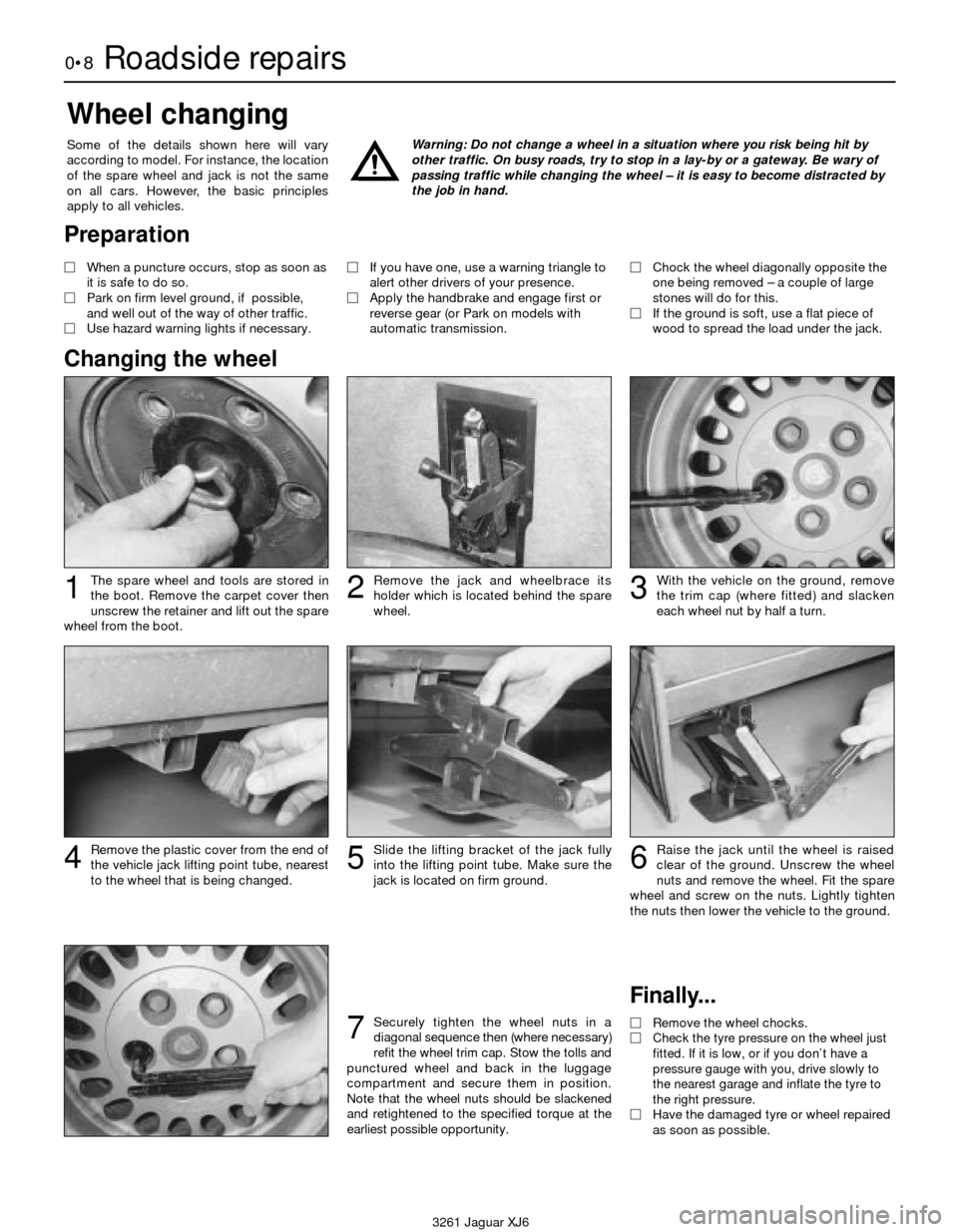
The spare wheel and tools are stored in
the boot. Remove the carpet cover then
unscrew the retainer and lift out the spare
wheel from the boot.
Wheel changing
Some of the details shown here will vary
according to model. For instance, the location
of the spare wheel and jack is not the same
on all cars. However, the basic principles
apply to all vehicles.Warning: Do not change a wheel in a situation where you risk being hit by
other traffic. On busy roads, try to stop in a lay-by or a gateway. Be wary of
passing traffic while changing the wheel – it is easy to become distracted by
the job in hand.
Finally...
MRemove the wheel chocks.
MCheck the tyre pressure on the wheel just
fitted. If it is low, or if you don’t have a
pressure gauge with you, drive slowly to
the nearest garage and inflate the tyre to
the right pressure.
MHave the damaged tyre or wheel repaired
as soon as possible.
Remove the plastic cover from the end of
the vehicle jack lifting point tube, nearest
to the wheel that is being changed.Slide the lifting bracket of the jack fully
into the lifting point tube. Make sure the
jack is located on firm ground.Raise the jack until the wheel is raised
clear of the ground. Unscrew the wheel
nuts and remove the wheel. Fit the spare
wheel and screw on the nuts. Lightly tighten
the nuts then lower the vehicle to the ground.
With the vehicle on the ground, remove
the trim cap (where fitted) and slacken
each wheel nut by half a turn.Remove the jack and wheelbrace its
holder which is located behind the spare
wheel.123
4
Securely tighten the wheel nuts in a
diagonal sequence then (where necessary)
refit the wheel trim cap. Stow the tolls and
punctured wheel and back in the luggage
compartment and secure them in position.
Note that the wheel nuts should be slackened
and retightened to the specified torque at the
earliest possible opportunity.7
56
Preparation
MWhen a puncture occurs, stop as soon as
it is safe to do so.
MPark on firm level ground, if possible,
and well out of the way of other traffic.
MUse hazard warning lights if necessary. MIf you have one, use a warning triangle to
alert other drivers of your presence.
MApply the handbrake and engage first or
reverse gear (or Park on models with
automatic transmission.MChock the wheel diagonally opposite the
one being removed – a couple of large
stones will do for this.
MIf the ground is soft, use a flat piece of
wood to spread the load under the jack.
Changing the wheel
Page 18 of 227
Lubricants and fluids
Refer to “Weekly checks”
Capacities
Engine oil
Including oil filter . . . . . . . . . . . . . . . . . . . . . . . . . . . . . . . . . . . . . . . . . . . 8.0 litres
Cooling system
All models (approximate):
From dry . . . . . . . . . . . . . . . . . . . . . . . . . . . . . . . . . . . . . . . . . . . . . . . 12.8 litres
Drain and refill . . . . . . . . . . . . . . . . . . . . . . . . . . . . . . . . . . . . . . . . . . . 9.2 litres
Transmission
Automatic transmission (approximate):
From dry:
3.2 litre model . . . . . . . . . . . . . . . . . . . . . . . . . . . . . . . . . . . . . . . . . 7.4 litres
3.6 and 4.0 litre models . . . . . . . . . . . . . . . . . . . . . . . . . . . . . . . . . 8.0 litres
Drain and refill . . . . . . . . . . . . . . . . . . . . . . . . . . . . . . . . . . . . . . . . . . . 3.0 litres
Differential
All models (approximate) . . . . . . . . . . . . . . . . . . . . . . . . . . . . . . . . . . . . 2.1 litres
Cooling system
Antifreeze mixture:
50% antifreeze . . . . . . . . . . . . . . . . . . . . . . . . . . . . . . . . . . . . . . . . . . Protection down to -37°C (5°F)
55% antifreeze . . . . . . . . . . . . . . . . . . . . . . . . . . . . . . . . . . . . . . . . . . Protection down to -45°C (-22°F)
Note:Refer to antifreeze manufacturer for latest recommendations.
Ignition system
Spark plugs:
Type:
3.2 litre model . . . . . . . . . . . . . . . . . . . . . . . . . . . . . . . . . . . . . . . . . RC12YCC
3.6 and 4.0 litre models . . . . . . . . . . . . . . . . . . . . . . . . . . . . . . . . . RC9YCC
Electrode gap . . . . . . . . . . . . . . . . . . . . . . . . . . . . . . . . . . . . . . . . . . . 0.9 mm
*The spark plug gap quoted is that recommended by Champion
for their specified plug listed above. If spark plugs of any other type
are to be fitted, refer to their manufacturer’s recommendations.
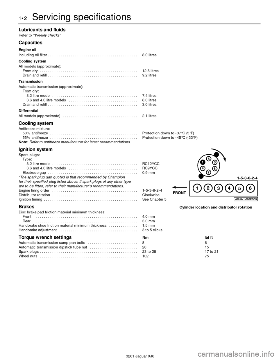
Engine firing order . . . . . . . . . . . . . . . . . . . . . . . . . . . . . . . . . . . . . . . . . 1-5-3-6-2-4
Distributor rotation . . . . . . . . . . . . . . . . . . . . . . . . . . . . . . . . . . . . . . . . . Clockwise
Ignition timing . . . . . . . . . . . . . . . . . . . . . . . . . . . . . . . . . . . . . . . . . . . . . See Chapter 5
Brakes
Disc brake pad friction material minimum thickness:
Front . . . . . . . . . . . . . . . . . . . . . . . . . . . . . . . . . . . . . . . . . . . . . . . . . 4.0 mm
Rear . . . . . . . . . . . . . . . . . . . . . . . . . . . . . . . . . . . . . . . . . . . . . . . . . 3.0 mm
Handbrake shoe friction material minimum thickness . . . . . . . . . . . . . . 1.5 mm
Handbrake adjustment . . . . . . . . . . . . . . . . . . . . . . . . . . . . . . . . . . . . . . 3 to 5 clicks
Torque wrench settingsNm lbf ft
Automatic transmission sump pan bolts . . . . . . . . . . . . . . . . . . . . . . . . 8 6
Automatic transmission dipstick tube nut . . . . . . . . . . . . . . . . . . . . . . . 20 15
Spark plugs . . . . . . . . . . . . . . . . . . . . . . . . . . . . . . . . . . . . . . . . . . . . . . . 23 to 28 17 to 21
Wheel nuts . . . . . . . . . . . . . . . . . . . . . . . . . . . . . . . . . . . . . . . . . . . . . . . 102 75
1•2Servicing specifications
3261 Jaguar XJ6
Cylinder location and distributor rotation
Page 19 of 227
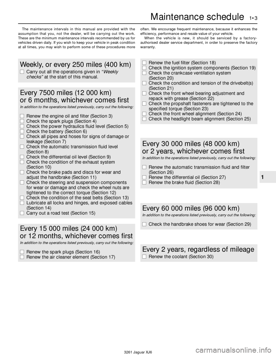
The maintenance intervals in this manual are provided with the
assumption that you, not the dealer, will be carrying out the work.
These are the minimum maintenance intervals recommended by us for
vehicles driven daily. If you wish to keep your vehicle in peak condition
at all times, you may wish to perform some of these procedures moreoften. We encourage frequent maintenance, because it enhances the
efficiency, performance and resale value of your vehicle.
When the vehicle is new, it should be serviced by a factory-
authorised dealer service department, in order to preserve the factory
warranty.
Maintenance schedule 1•3
1
3261 Jaguar XJ6
Weekly, or every 250 miles (400 km)
m mCarry out all the operations given in “Weekly
checks”at the start of this manual.
m
mRenew the fuel filter (Section 18)
m mCheck the ignition system components (Section 19)
m mCheck the crankcase ventilation system
(Section 20)
m mCheck the condition and tension of the drivebelt(s)
(Section 21)
m mCheck the front wheel bearing adjustment and
repack with grease (Section 22)
m mCheck the propshaft fasteners are tightened to the
specified torque (Section 23)
m mCheck the front wheel alignment (Section 24)
m mCheck the headlight beam alignment (Section 25)
Every 7500 miles (12 000 km)
or 6 months, whichever comes first
In addition to the operations listed previously, carry out the following:
m mRenew the engine oil and filter (Section 3)
m mCheck the spark plugs (Section 4)
m mCheck the power hydraulics fluid level (Section 5)
m mCheck the battery (Section 6)
m mCheck all pipes and hoses for signs of damage or
leakage (Section 7)
m mCheck the automatic transmission fluid level
(Section 8)
m mCheck the differential oil level (Section 9)
m mCheck the condition of the exhaust system
(Section 10)
m mCheck the brake pads and discs for wear and
adjust the handbrake (Section 11)
m mCheck the steering and suspension components
for wear or damage and check the wheel nuts are
tightened to the correct torque (Section 12)
m mCheck the condition of the seat belts (Section 13)
m mLubricate all locks and hinges, and exposed cables
(Section 14)
m mCarry out a road test (Section 15)
Every 2 years, regardless of mileage
m
mRenew the coolant (Section 30)
Every 60 000 miles (96 000 km)
In addition to the operations listed previously, carry out the following:
m
mCheck the handbrake shoes for wear (Section 29)
Every 30 000 miles (48 000 km)
or 2 years, whichever comes first
In addition to the operations listed previously, carry out the following:
m mRenew the automatic transmission fluid and filter
(Section 26)
m mRenew the differential oil (Section 27)
m mRenew the brake fluid (Section 28)
Every 15 000 miles (24 000 km)
or 12 months, whichever comes first
In addition to the operations listed previously, carry out the following:
m mRenew the spark plugs (Section 16)
m mRenew the air cleaner element (Section 17)
Page 23 of 227
exhaust components will be warm during the
actual work, so try to anticipate any potential
problems before the engine and accessories
are hot.
5Park the vehicle on a level spot. Start the
engine and allow it to reach its normal
operating temperature (the needle on the
temperature gauge should be at least above
the bottom mark). Warm oil and contaminates
will flow out more easily. Turn off the engine
when it’s warmed up. Remove the oil filler cap
located next to the valve cover.
6Raise the vehicle and support it on axle
stands.
Warning: To avoid personal
injury, never get beneath the
vehicle when it is supported by
only by a jack. The jack provided
with your vehicle is designed solely for
raising the vehicle to remove and replace
the wheels. Always use axle stands to
support the vehicle when it becomes
necessary to place your body underneath
the vehicle.
7Being careful not to touch the hot exhaust
components, place the drain pan under the
drain plug in the bottom of the pan and
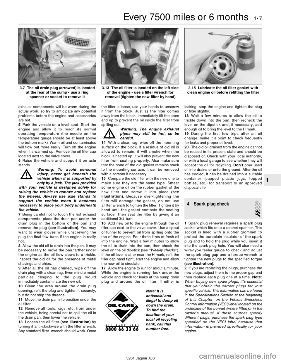
remove the plug (see illustration). You may
want to wear gloves while unscrewing the
plug the final few turns if the engine is really
hot.
8Allow the old oil to drain into the pan. It may
be necessary to move the pan farther under
the engine as the oil flow slows to a trickle.
Inspect the old oil for the presence of metal
shavings and chips.
9After all the oil has drained, wipe off the
drain plug with a clean rag. Even minute metal
particles clinging to the plug would
immediately contaminate the new oil.
10Clean the area around the drain plug
opening, refit the plug and tighten it securely,
but do not strip the threads.
11Move the drain pan into position under the
oil filter.
12Remove all tools, rags, etc. from under
the vehicle, being careful not to spill the oil in
the drain pan, then lower the vehicle.
13Loosen the oil filter (see illustration)by
turning it anti-clockwise with the filter wrench.
Any standard filter wrench should work. Oncethe filter is loose, use your hands to unscrew
it from the block. Just as the filter comes
away from the block, immediately tilt the open
end up to prevent the oil inside the filter from
spilling out.
Warning: The engine exhaust
pipes may still be hot, so be
careful.
14With a clean rag, wipe off the mounting
surface on the block. If a residue of old oil is
allowed to remain, it will smoke when the
block is heated up. It will also prevent the new
filter from seating properly. Also make sure
that the none of the old gasket remains stuck
to the mounting surface. It can be removed
with a scraper if necessary.
15Compare the old filter with the new one to
make sure they are the same type. Smear
some engine oil on the rubber gasket of the
new filter and screw it into place (see
illustration). Because over-tightening the
filter will damage the gasket, do not use
a filter wrench to tighten the filter. Tighten it by
hand until the gasket contacts the seating
surface. Then seat the filter by giving it an
additional 3/4-turn.
16Add new oil to the engine through the oil
filler cap next to the valve cover. Use a spout
or funnel to prevent oil from spilling onto the
top of the engine. Pour three litres of fresh oil
into the engine. Wait a few minutes to allow
the oil to drain into the pan, then check the
level on the oil dipstick (see “Weekly checks”).
If the oil level is at or near the H mark, refit the
filler cap hand tight, start the engine and allow
the new oil to circulate.
17Allow the engine to run for about a minute.
While the engine is running, look under the
vehicle and check for leaks at the sump drain
plug and around the oil filter. If either isleaking, stop the engine and tighten the plug
or filter slightly.
18Wait a few minutes to allow the oil to
trickle down into the pan, then recheck the
level on the dipstick and, if necessary, add
enough oil to bring the level to the H mark.
19During the first few trips after an oil
change, make it a point to check frequently
for leaks and proper oil level.
20The old oil drained from the engine cannot
be reused in its present state and should be
disposed of. Check with your local authority,
or with a local garage to see whether they will
accept the oil for recycling. Don’tpour used
oil into drains or onto the ground. After the oil
has cooled, it can be drained into a suitable
container (capped plastic jugs, topped
bottles, etc.) for transport to an approved
disposal site.
4 Spark plug check
2
1Spark plug renewal requires a spark plug
socket which fits onto a ratchet spanner. This
socket is lined with a rubber grommet to
protect the porcelain insulator of the spark
plug and to hold the plug while you insert it
into the spark plug hole. You will also need a
wire-type feeler gauge to check and adjust
the spark plug gap and a torque wrench to
tighten the new plugs to the specified torque
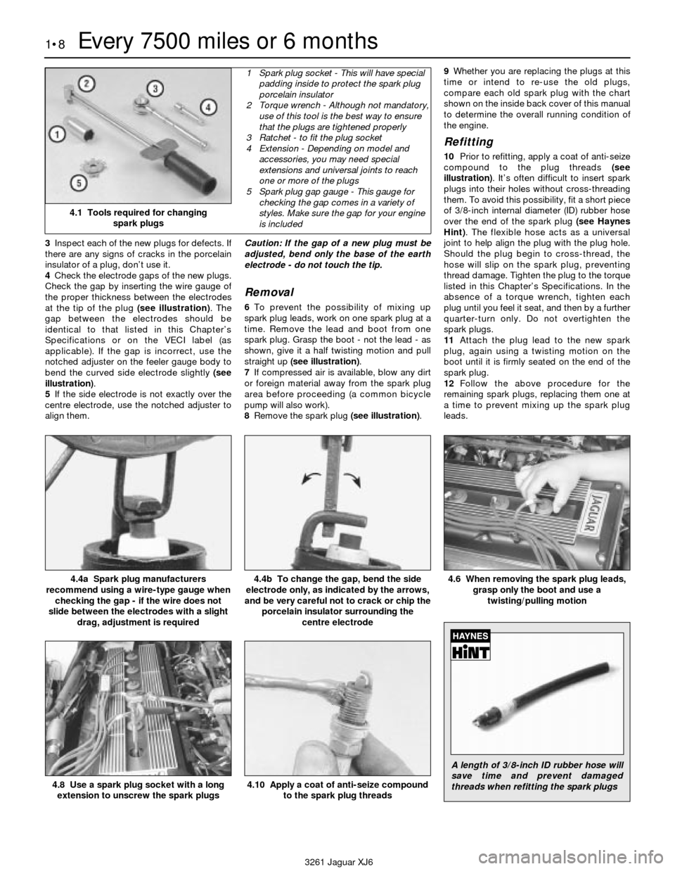
(see illustration).
2If you are replacing the plugs, purchase the
new plugs, adjust them to the proper gap and
then replace each plug one at a time. Note:
When buying new spark plugs, it’s essential
that you obtain the correct plugs for your
specific vehicle. This information can be found
in the Specifications Section at the beginning
of this Chapter, on the Vehicle Emissions
Control Information (VECI) label located on the
underside of the bonnet (where fitted)or in the
owner’s manual. If these sources specify
different plugs, purchase the spark plug type
specified on the VECI label because that
information is provided specifically for your
engine.
Every 7500 miles or 6 months 1•7
1
3.7 The oil drain plug (arrowed) is located
at the rear of the sump - use a ring
spanner or socket to remove it3.13 The oil filter is located on the left side
of the engine - use a filter wrench for
removal (tighten the new filter by hand)3.15 Lubricate the oil filter gasket with
clean engine oil before refitting the filter
3261 Jaguar XJ6
Note: It is
antisocial and
illegal to dump oil
down the drain.
To find the
location of your
local oil recycling
bank, call this
number free.
Page 24 of 227
3Inspect each of the new plugs for defects. If
there are any signs of cracks in the porcelain
insulator of a plug, don’t use it.
4Check the electrode gaps of the new plugs.
Check the gap by inserting the wire gauge of
the proper thickness between the electrodes
at the tip of the plug (see illustration). The
gap between the electrodes should be
identical to that listed in this Chapter’s
Specifications or on the VECI label (as
applicable). If the gap is incorrect, use the
notched adjuster on the feeler gauge body to
bend the curved side electrode slightly (see
illustration).
5If the side electrode is not exactly over the
centre electrode, use the notched adjuster to
align them.Caution: If the gap of a new plug must be
adjusted, bend only the base of the earth
electrode - do not touch the tip.
Removal
6To prevent the possibility of mixing up
spark plug leads, work on one spark plug at a
time. Remove the lead and boot from one
spark plug. Grasp the boot - not the lead - as
shown, give it a half twisting motion and pull
straight up (see illustration).
7If compressed air is available, blow any dirt
or foreign material away from the spark plug
area before proceeding (a common bicycle
pump will also work).
8Remove the spark plug (see illustration).9Whether you are replacing the plugs at this
time or intend to re-use the old plugs,
compare each old spark plug with the chart
shown on the inside back cover of this manual
to determine the overall running condition of
the engine.
Refitting
10Prior to refitting, apply a coat of anti-seize
compound to the plug threads (see
illustration). It’s often difficult to insert spark
plugs into their holes without cross-threading
them. To avoid this possibility, fit a short piece
of 3/8-inch internal diameter (ID) rubber hose
over the end of the spark plug (see Haynes
Hint). The flexible hose acts as a universal
joint to help align the plug with the plug hole.
Should the plug begin to cross-thread, the
hose will slip on the spark plug, preventing
thread damage. Tighten the plug to the torque
listed in this Chapter’s Specifications. In the
absence of a torque wrench, tighten each
plug until you feel it seat, and then by a further
quarter-turn only. Do not overtighten the
spark plugs.
11Attach the plug lead to the new spark
plug, again using a twisting motion on the
boot until it is firmly seated on the end of the
spark plug.
12Follow the above procedure for the
remaining spark plugs, replacing them one at
a time to prevent mixing up the spark plug
leads.
1•8Every 7500 miles or 6 months
4.4a Spark plug manufacturers
recommend using a wire-type gauge when
checking the gap - if the wire does not
slide between the electrodes with a slight
drag, adjustment is required4.4b To change the gap, bend the side
electrode only, as indicated by the arrows,
and be very careful not to crack or chip the
porcelain insulator surrounding the
centre electrode4.6 When removing the spark plug leads,
grasp only the boot and use a
twisting/pulling motion
4.8 Use a spark plug socket with a long
extension to unscrew the spark plugs
3261 Jaguar XJ6
4.1 Tools required for changing
spark plugs
1 Spark plug socket - This will have special
padding inside to protect the spark plug
porcelain insulator
2 Torque wrench - Although not mandatory,
use of this tool is the best way to ensure
that the plugs are tightened properly
3 Ratchet - to fit the plug socket
4 Extension - Depending on model and
accessories, you may need special
extensions and universal joints to reach
one or more of the plugs
5 Spark plug gap gauge - This gauge for
checking the gap comes in a variety of
styles. Make sure the gap for your engine
is included
4.10 Apply a coat of anti-seize compound
to the spark plug threads
A length of 3/8-inch ID rubber hose will
save time and prevent damaged
threads when refitting the spark plugs
Page 28 of 227
silencer and catalytic converter. If the
components can come in contact with the
body or suspension parts, secure the exhaust
system with new mounts.
5Check the running condition of the engine
by inspecting inside the end of the tailpipe.
The exhaust deposits here are an indication of
engine state-of-tune. If the pipe is black and
sooty or coated with white deposits, the
engine is in need of a tune-up, including a
thorough fuel system inspection.
11 Braking system - general
check and adjustment
2
Warning: The dust created by
the brake system may contain
asbestos, which is harmful to
your health. Never blow it out
with compressed air and don’t inhale any
of it. An approved filtering mask should be
worn when working on the brakes. Do not,
under any circumstances, use petroleum-
based solvents to clean brake parts. Use
brake system cleaner only! Try to use non-
asbestos replacement parts whenever
possible.
Note: For detailed photographs of the brake
system, refer to Chapter 9.
1In addition to the specified intervals, the
brakes should be inspected every time the
wheels are removed or whenever a defect is
suspected. Any of the following symptoms
could indicate a potential brake system
defect: The vehicle pulls to one side when the
brake pedal is depressed; the brakes make
squealing or dragging noises when applied;
brake pedal travel is excessive; the pedal
pulsates; brake fluid leaks, usually onto the
inside of the tyre or wheel.
2The disc brakes have built-in electrical wear
indicators which cause a warning lamp to
illuminate on the instrument panel when
they’re worn to the renewal point. When the
warning light comes on, replace the pads
immediately or expensive damage to the
discs can result.
3Loosen the wheel nuts.
4Raise the vehicle and place it securely on
axle stands.
5Remove the wheels.
Disc brakes
6There are two pads (an outer and an inner)
in each caliper. The pads are visible through
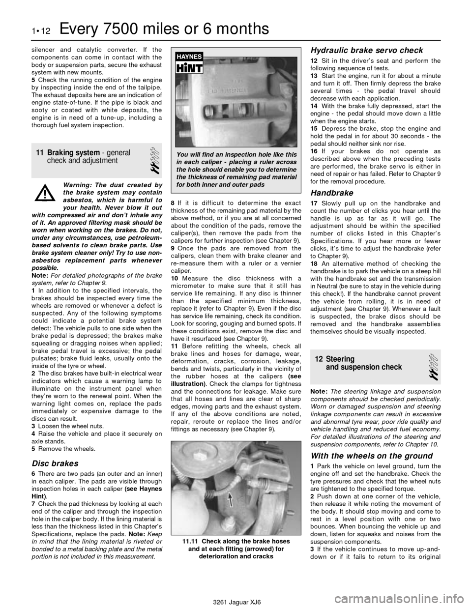
inspection holes in each caliper (see Haynes
Hint).
7Check the pad thickness by looking at each
end of the caliper and through the inspection
hole in the caliper body. If the lining material is
less than the thickness listed in this Chapter’s
Specifications, replace the pads. Note:Keep
in mind that the lining material is riveted or
bonded to a metal backing plate and the metal
portion is not included in this measurement.8If it is difficult to determine the exact
thickness of the remaining pad material by the
above method, or if you are at all concerned
about the condition of the pads, remove the
caliper(s), then remove the pads from the
calipers for further inspection (see Chapter 9).
9Once the pads are removed from the
calipers, clean them with brake cleaner and
re-measure them with a ruler or a vernier
caliper.
10Measure the disc thickness with a
micrometer to make sure that it still has
service life remaining. If any disc is thinner
than the specified minimum thickness,
replace it (refer to Chapter 9). Even if the disc
has service life remaining, check its condition.
Look for scoring, gouging and burned spots. If
these conditions exist, remove the disc and
have it resurfaced (see Chapter 9).
11Before refitting the wheels, check all
brake lines and hoses for damage, wear,
deformation, cracks, corrosion, leakage,
bends and twists, particularly in the vicinity of
the rubber hoses at the calipers (see
illustration). Check the clamps for tightness
and the connections for leakage. Make sure
that all hoses and lines are clear of sharp
edges, moving parts and the exhaust system.
If any of the above conditions are noted,
repair, reroute or replace the lines and/or
fittings as necessary (see Chapter 9).
Hydraulic brake servo check
12Sit in the driver’s seat and perform the
following sequence of tests.
13Start the engine, run it for about a minute
and turn it off. Then firmly depress the brake
several times - the pedal travel should
decrease with each application.
14With the brake fully depressed, start the
engine - the pedal should move down a little
when the engine starts.
15Depress the brake, stop the engine and
hold the pedal in for about 30 seconds - the
pedal should neither sink nor rise.
16If your brakes do not operate as
described above when the preceding tests
are performed, the brake servo is either in
need of repair or has failed. Refer to Chapter 9
for the removal procedure.
Handbrake
17Slowly pull up on the handbrake and
count the number of clicks you hear until the
handle is up as far as it will go. The
adjustment should be within the specified
number of clicks listed in this Chapter’s
Specifications. If you hear more or fewer
clicks, it’s time to adjust the handbrake (refer
to Chapter 9).
18An alternative method of checking the
handbrake is to park the vehicle on a steep hill
with the handbrake set and the transmission
in Neutral (be sure to stay in the vehicle during
this check!). If the handbrake cannot prevent
the vehicle from rolling, it is in need of
adjustment (see Chapter 9). Whenever a fault
is suspected, the brake discs should be
removed and the handbrake assemblies
themselves should be visually inspected.
12 Steering
and suspension check
2
Note: The steering linkage and suspension
components should be checked periodically.
Worn or damaged suspension and steering
linkage components can result in excessive
and abnormal tyre wear, poor ride quality and
vehicle handling and reduced fuel economy.
For detailed illustrations of the steering and
suspension components, refer to Chapter 10.
With the wheels on the ground
1Park the vehicle on level ground, turn the
engine off and set the handbrake. Check the
tyre pressures and check that the wheel nuts
are tightened to the specified torque.
2Push down at one corner of the vehicle,
then release it while noting the movement of
the body. It should stop moving and come to
rest in a level position with one or two
bounces. When bouncing the vehicle up and
down, listen for squeaks and noises from the
suspension components.
3If the vehicle continues to move up-and-
down or if it fails to return to its original
1•12Every 7500 miles or 6 months
11.11 Check along the brake hoses
and at each fitting (arrowed) for
deterioration and cracks
3261 Jaguar XJ6
You will find an inspection hole like this
in each caliper - placing a ruler across
the hole should enable you to determine
the thickness of remaining pad material
for both inner and outer pads
Page 33 of 227
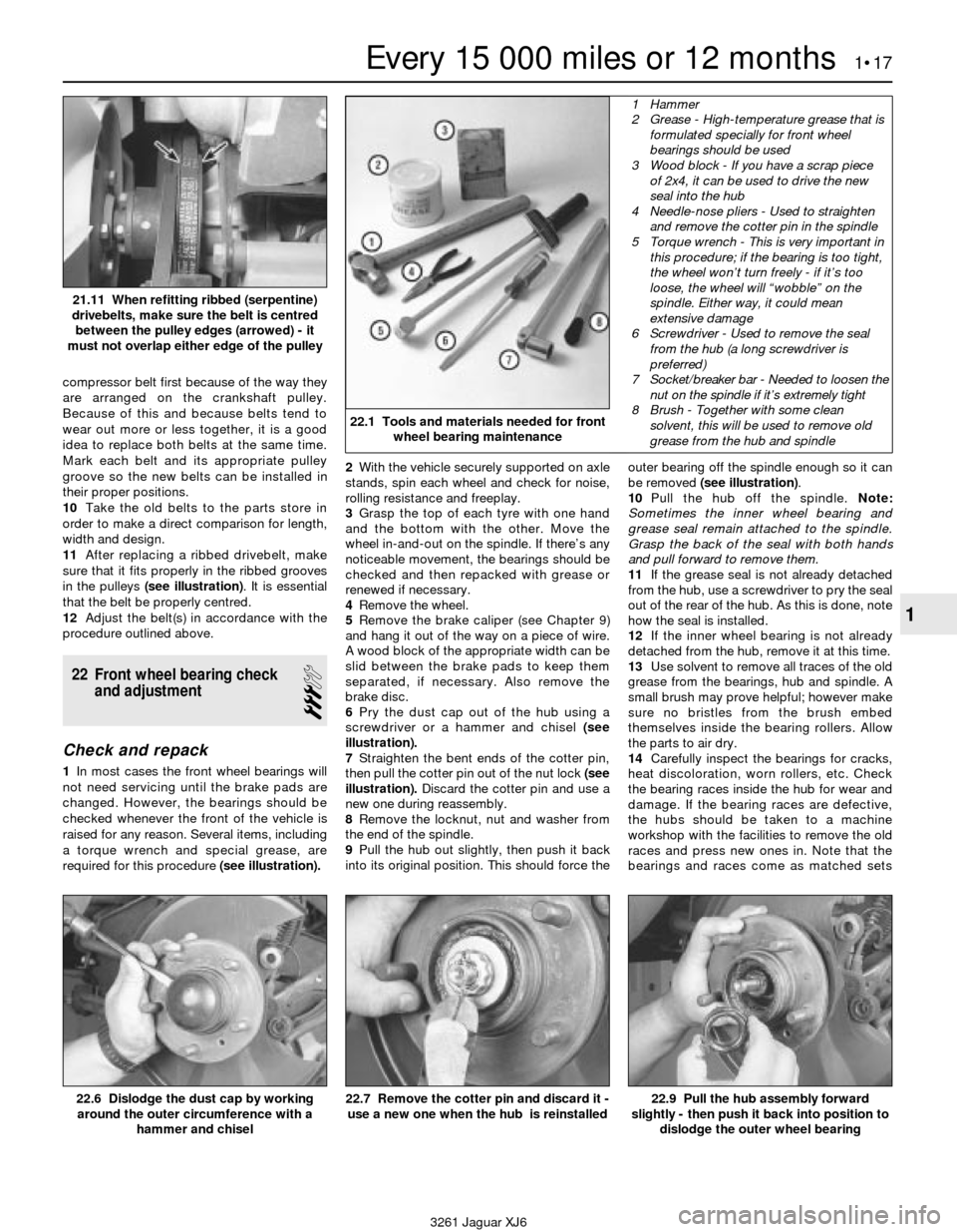
compressor belt first because of the way they
are arranged on the crankshaft pulley.
Because of this and because belts tend to
wear out more or less together, it is a good
idea to replace both belts at the same time.
Mark each belt and its appropriate pulley
groove so the new belts can be installed in
their proper positions.
10Take the old belts to the parts store in
order to make a direct comparison for length,
width and design.
11After replacing a ribbed drivebelt, make
sure that it fits properly in the ribbed grooves
in the pulleys (see illustration). It is essential
that the belt be properly centred.
12Adjust the belt(s) in accordance with the
procedure outlined above.
22 Front wheel bearing check
and adjustment
3
Check and repack
1In most cases the front wheel bearings will
not need servicing until the brake pads are
changed. However, the bearings should be
checked whenever the front of the vehicle is
raised for any reason. Several items, including
a torque wrench and special grease, are
required for this procedure (see illustration).2With the vehicle securely supported on axle
stands, spin each wheel and check for noise,
rolling resistance and freeplay.
3Grasp the top of each tyre with one hand
and the bottom with the other. Move the
wheel in-and-out on the spindle. If there’s any
noticeable movement, the bearings should be
checked and then repacked with grease or
renewed if necessary.
4Remove the wheel.
5Remove the brake caliper (see Chapter 9)
and hang it out of the way on a piece of wire.
A wood block of the appropriate width can be
slid between the brake pads to keep them
separated, if necessary. Also remove the
brake disc.
6Pry the dust cap out of the hub using a
screwdriver or a hammer and chisel (see
illustration).
7Straighten the bent ends of the cotter pin,
then pull the cotter pin out of the nut lock (see
illustration).Discard the cotter pin and use a
new one during reassembly.
8Remove the locknut, nut and washer from
the end of the spindle.
9Pull the hub out slightly, then push it back
into its original position. This should force theouter bearing off the spindle enough so it can
be removed (see illustration).
10Pull the hub off the spindle. Note:
Sometimes the inner wheel bearing and
grease seal remain attached to the spindle.
Grasp the back of the seal with both hands
and pull forward to remove them.
11If the grease seal is not already detached
from the hub, use a screwdriver to pry the seal
out of the rear of the hub. As this is done, note
how the seal is installed.
12If the inner wheel bearing is not already
detached from the hub, remove it at this time.
13Use solvent to remove all traces of the old
grease from the bearings, hub and spindle. A
small brush may prove helpful; however make
sure no bristles from the brush embed
themselves inside the bearing rollers. Allow
the parts to air dry.
14Carefully inspect the bearings for cracks,
heat discoloration, worn rollers, etc. Check
the bearing races inside the hub for wear and
damage. If the bearing races are defective,
the hubs should be taken to a machine
workshop with the facilities to remove the old
races and press new ones in. Note that the
bearings and races come as matched sets
Every 15 000 miles or 12 months 1•17
1
22.1 Tools and materials needed for front
wheel bearing maintenance
1 Hammer
2 Grease - High-temperature grease that is
formulated specially for front wheel
bearings should be used
3 Wood block - If you have a scrap piece
of 2x4, it can be used to drive the new
seal into the hub
4 Needle-nose pliers - Used to straighten
and remove the cotter pin in the spindle
5 Torque wrench - This is very important in
this procedure; if the bearing is too tight,
the wheel won’t turn freely - if it’s too
loose, the wheel will “wobble” on the
spindle. Either way, it could mean
extensive damage
6 Screwdriver - Used to remove the seal
from the hub (a long screwdriver is
preferred)
7 Socket/breaker bar - Needed to loosen the
nut on the spindle if it’s extremely tight
8 Brush - Together with some clean
solvent, this will be used to remove old
grease from the hub and spindle
22.6 Dislodge the dust cap by working
around the outer circumference with a
hammer and chisel
22.7 Remove the cotter pin and discard it -
use a new one when the hub is reinstalled22.9 Pull the hub assembly forward
slightly - then push it back into position to
dislodge the outer wheel bearing
3261 Jaguar XJ6 21.11 When refitting ribbed (serpentine)
drivebelts, make sure the belt is centred
between the pulley edges (arrowed) - it
must not overlap either edge of the pulley
Page 34 of 227
and old bearings should never be installed on
new races.
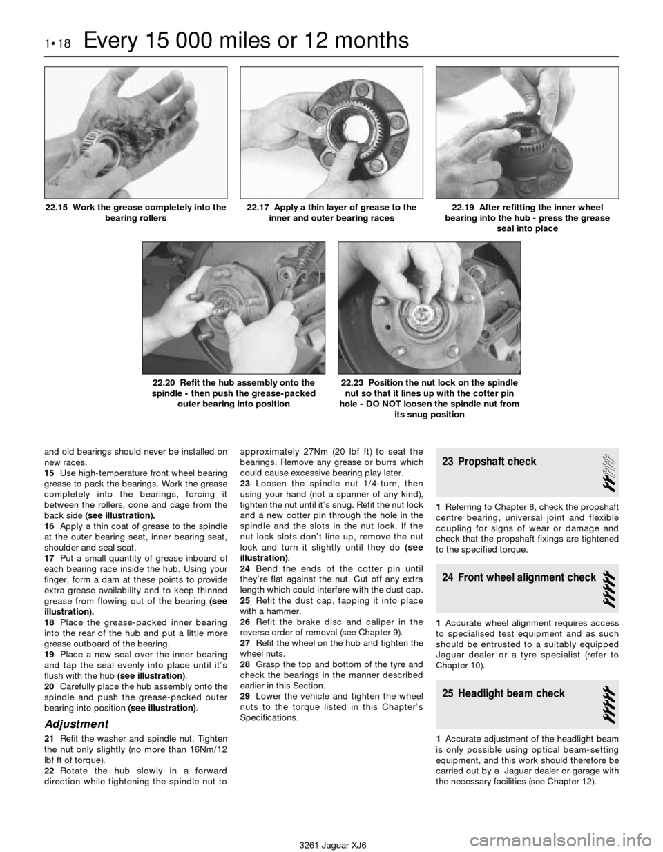
15Use high-temperature front wheel bearing
grease to pack the bearings. Work the grease
completely into the bearings, forcing it
between the rollers, cone and cage from the
back side (see illustration).
16Apply a thin coat of grease to the spindle
at the outer bearing seat, inner bearing seat,
shoulder and seal seat.
17Put a small quantity of grease inboard of
each bearing race inside the hub. Using your
finger, form a dam at these points to provide
extra grease availability and to keep thinned
grease from flowing out of the bearing (see
illustration).
18Place the grease-packed inner bearing
into the rear of the hub and put a little more
grease outboard of the bearing.
19Place a new seal over the inner bearing
and tap the seal evenly into place until it’s
flush with the hub (see illustration).
20Carefully place the hub assembly onto the
spindle and push the grease-packed outer
bearing into position (see illustration).
Adjustment
21Refit the washer and spindle nut. Tighten
the nut only slightly (no more than 16Nm/12
lbf ft of torque).
22Rotate the hub slowly in a forward
direction while tightening the spindle nut toapproximately 27Nm (20 lbf ft) to seat the
bearings. Remove any grease or burrs which
could cause excessive bearing play later.
23Loosen the spindle nut 1/4-turn, then
using your hand (not a spanner of any kind),
tighten the nut until it’s snug. Refit the nut lock
and a new cotter pin through the hole in the
spindle and the slots in the nut lock. If the
nut lock slots don’t line up, remove the nut
lock and turn it slightly until they do (see
illustration).
24Bend the ends of the cotter pin until
they’re flat against the nut. Cut off any extra
length which could interfere with the dust cap.
25Refit the dust cap, tapping it into place
with a hammer.
26Refit the brake disc and caliper in the
reverse order of removal (see Chapter 9).
27Refit the wheel on the hub and tighten the
wheel nuts.
28Grasp the top and bottom of the tyre and
check the bearings in the manner described
earlier in this Section.
29Lower the vehicle and tighten the wheel
nuts to the torque listed in this Chapter’s
Specifications.
23 Propshaft check
2
1Referring to Chapter 8, check the propshaft
centre bearing, universal joint and flexible
coupling for signs of wear or damage and
check that the propshaft fixings are tightened
to the specified torque.
24 Front wheel alignment check
5
1Accurate wheel alignment requires access
to specialised test equipment and as such
should be entrusted to a suitably equipped
Jaguar dealer or a tyre specialist (refer to
Chapter 10).
25 Headlight beam check
5
1Accurate adjustment of the headlight beam
is only possible using optical beam-setting
equipment, and this work should therefore be
carried out by a Jaguar dealer or garage with
the necessary facilities (see Chapter 12).
1•18Every 15 000 miles or 12 months
22.15 Work the grease completely into the
bearing rollers22.17 Apply a thin layer of grease to the
inner and outer bearing races22.19 After refitting the inner wheel
bearing into the hub - press the grease
seal into place
22.20 Refit the hub assembly onto the
spindle - then push the grease-packed
outer bearing into position22.23 Position the nut lock on the spindle
nut so that it lines up with the cotter pin
hole - DO NOT loosen the spindle nut from
its snug position
3261 Jaguar XJ6