JEEP CHEROKEE 1994 Service Repair Manual
Manufacturer: JEEP, Model Year: 1994, Model line: CHEROKEE, Model: JEEP CHEROKEE 1994Pages: 1784, PDF Size: 77.09 MB
Page 1301 of 1784
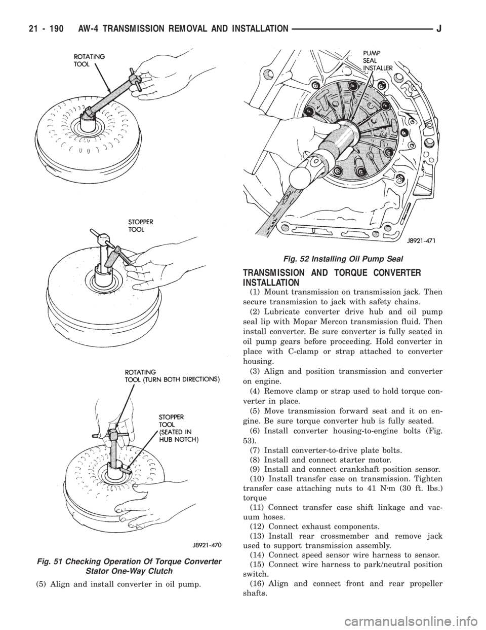
(5) Align and install converter in oil pump.
TRANSMISSION AND TORQUE CONVERTER
INSTALLATION
(1) Mount transmission on transmission jack. Then
secure transmission to jack with safety chains.
(2) Lubricate converter drive hub and oil pump
seal lip with Mopar Mercon transmission fluid. Then
install converter. Be sure converter is fully seated in
oil pump gears before proceeding. Hold converter in
place with C-clamp or strap attached to converter
housing.
(3) Align and position transmission and converter
on engine.
(4) Remove clamp or strap used to hold torque con-
verter in place.
(5) Move transmission forward seat and it on en-
gine. Be sure torque converter hub is fully seated.
(6)
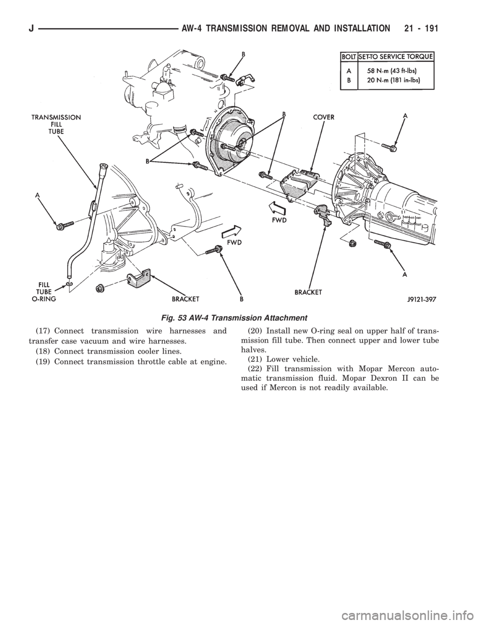
Install converter housing-to-engine bolts (Fig.
53).
(7) Install converter-to-drive plate bolts.
(8) Install and connect starter motor.
(9) Install and connect crankshaft position sensor.
(10) Install transfer case on transmission. Tighten
transfer case attaching nuts to 41 Nzm (30 ft. lbs.)
torque
(11) Connect transfer case shift linkage and vac-
uum hoses.
(12) Connect exhaust components.
(13) Install rear crossmember and remove jack
used to support transmission assembly.
(14) Connect speed sensor wire harness to sensor.
(15) Connect wire harness to park/neutral position
switch.
(16) Align and connect front and rear propeller
shafts.
Fig. 51 Checking Operation Of Torque Converter
Stator One-Way Clutch
Fig. 52 Installing Oil Pump Seal
21 - 190 AW-4 TRANSMISSION REMOVAL AND INSTALLATIONJ
Page 1302 of 1784
(17) Connect transmission wire harnesses and
transfer case vacuum and wire harnesses.
(18) Connect transmission cooler lines.
(19) Connect transmission throttle cable at engine.(20) Install new O-ring seal on upper half of trans-
mission fill tube. Then connect upper and lower tube
halves.
(21) Lower vehicle.
(22) Fill transmission with Mopar Mercon auto-
matic transmission fluid. Mopar Dexron II can be
used if Mercon is not readily available.
Fig. 53 AW-4 Transmission Attachment
JAW-4 TRANSMISSION REMOVAL AND INSTALLATION 21 - 191
Page 1303 of 1784
AW-4 TRANSMISSION OVERHAUL
INDEX
page page
Cleaning and Inspection................... 76
Direct Clutch Overhaul................... 219
First-Reverse Brake Piston and Transmission
Case Overhaul........................ 237
Forward Clutch Overhaul.................. 223
Front Planetary Gear Overhaul............. 228
Manual Valve Shaft Overhaul.............. 205
Oil Pump Overhaul...................... 206
Overdrive Planetary Gear and Clutch Overhaul . 209Overdrive Support Overhaul................ 216
Overhaul Service Tools................... 192
Rear Planetary, No. 2 One-Way Clutch and
Output Shaft Overhaul.................. 100
Second Brake Overhaul................... 100
Sun Gear and No. 1 One-Way Clutch Overhaul . 99
Transmission Assembly and Adjustment....... 255
Transmission Disassembly................. 192
Transmission Valve Body Overhaul.......... 101
OVERHAUL SERVICE TOOLS
The special tools needed to overhaul the AW-4
transmission are provided in Tool Kit 6294. However,
Pressure Test Port Adapter 7554 is not included in
this kit and must be ordered separately. The over-
haul tool kit and test port adapter are available
through the parts division and dealer special tool
program.
TRANSMISSION DISASSEMBLY
(1) Remove torque converter.
(2) Remove lower half of filler tube if not previ-
ously removed.
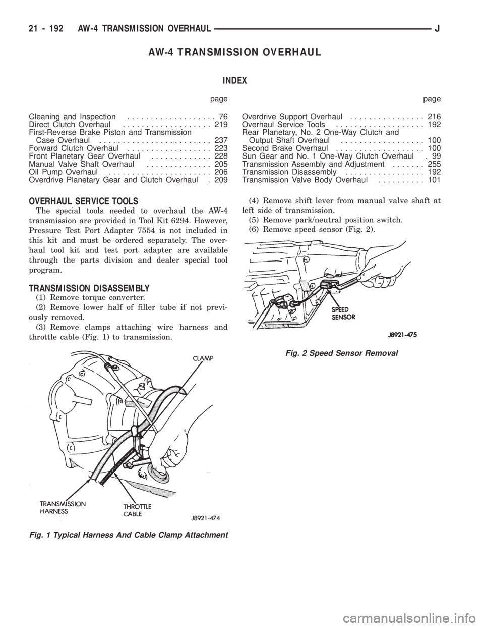
(3) Remove clamps attaching wire harness and
throttle cable (Fig. 1) to transmission.(4) Remove shift lever from manual valve shaft at
left side of transmission.
(5) Remove park/neutral position switch.
(6) Remove speed sensor (Fig. 2).
Fig. 1 Typical Harness And Cable Clamp Attachment
Fig. 2 Speed Sensor Removal
21 - 192 AW-4 TRANSMISSION OVERHAULJ
Page 1304 of 1784
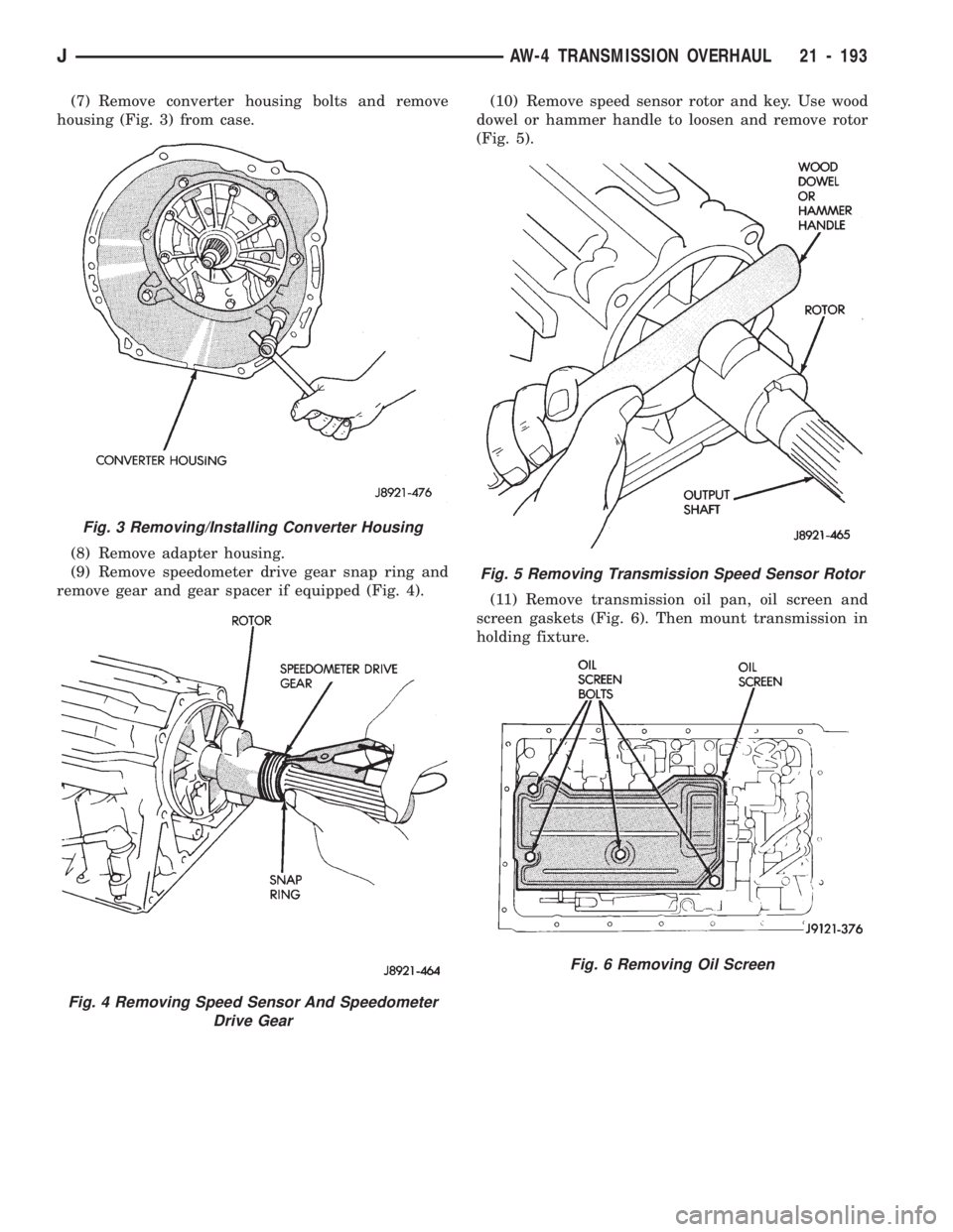
(7) Remove converter housing bolts and remove
housing (Fig. 3) from case.
(8) Remove adapter housing.
(9) Remove speedometer drive gear snap ring and
remove gear and gear spacer if equipped (Fig. 4).(10) Remove speed sensor rotor and key. Use wood
dowel or hammer handle to loosen and remove rotor
(Fig. 5).
(11) Remove transmission oil pan, oil screen and
screen gaskets (Fig. 6). Then mount transmission in
holding fixture.
Fig. 3 Removing/Installing Converter Housing
Fig. 4 Removing Speed Sensor And Speedometer
Drive Gear
Fig. 5 Removing Transmission Speed Sensor Rotor
Fig. 6 Removing Oil Screen
JAW-4 TRANSMISSION OVERHAUL 21 - 193
Page 1305 of 1784
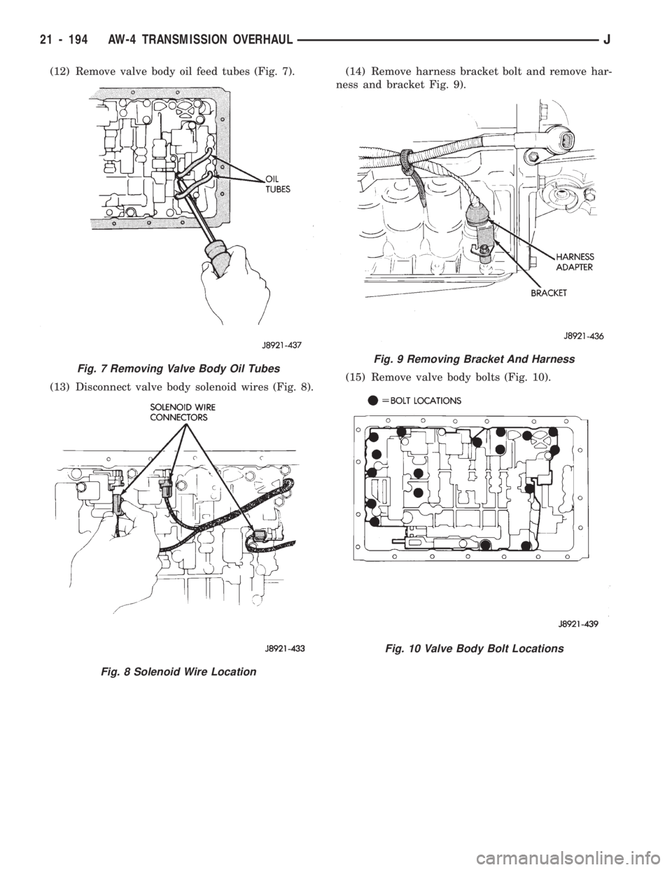
(12) Remove valve body oil feed tubes (Fig. 7).
(13) Disconnect valve body solenoid wires (Fig. 8).(14) Remove harness bracket bolt and remove har-
ness and bracket Fig. 9).
(15) Remove valve body bolts (Fig. 10).
Fig. 7 Removing Valve Body Oil Tubes
Fig. 8 Solenoid Wire Location
Fig. 9 Removing Bracket And Harness
Fig. 10 Valve Body Bolt Locations
21 - 194 AW-4 TRANSMISSION OVERHAULJ
Page 1306 of 1784
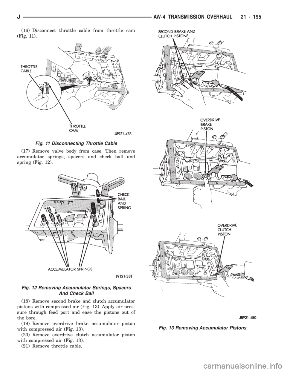
(16) Disconnect throttle cable from throttle cam
(Fig. 11).
(17) Remove valve body from case. Then remove
accumulator springs, spacers and check ball and
spring (Fig. 12).
(18) Remove second brake and clutch accumulator
pistons with compressed air (Fig. 13). Apply air pres-
sure through feed port and ease the pistons out of
the bore.
(19) Remove overdrive brake accumulator piston
with compressed air (Fig. 13).
(20) Remove overdrive clutch accumulator piston
with compressed air (Fig. 13).
(21) Remove throttle cable.
Fig. 11 Disconnecting Throttle Cable
Fig. 12 Removing Accumulator Springs, Spacers
And Check Ball
Fig. 13 Removing Accumulator Pistons
JAW-4 TRANSMISSION OVERHAUL 21 - 195
Page 1307 of 1784
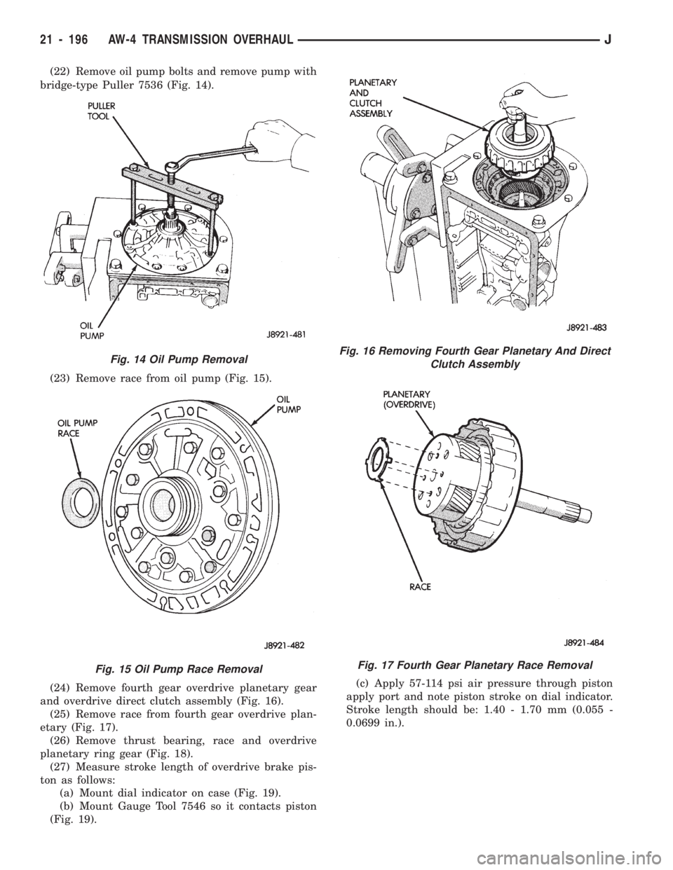
(22) Remove oil pump bolts and remove pump with
bridge-type Puller 7536 (Fig. 14).
(23) Remove race from oil pump (Fig. 15).
(24) Remove fourth gear overdrive planetary gear
and overdrive direct clutch assembly (Fig. 16).
(25) Remove race from fourth gear overdrive plan-
etary (Fig. 17).
(26) Remove thrust bearing, race and overdrive
planetary ring gear (Fig. 18).
(27) Measure stroke length of overdrive brake pis-
ton as follows:
(a) Mount dial indicator on case (Fig. 19).
(b) Mount Gauge Tool 7546 so it contacts piston
(Fig. 19).(c) Apply 57-114 psi air pressure through piston
apply port and note piston stroke on dial indicator.
Stroke length should be: 1.40 - 1.70 mm (0.055 -
0.0699 in.).
Fig. 14 Oil Pump Removal
Fig. 15 Oil Pump Race Removal
Fig. 16 Removing Fourth Gear Planetary And Direct
Clutch Assembly
Fig. 17 Fourth Gear Planetary Race Removal
21 - 196 AW-4 TRANSMISSION OVERHAULJ
Page 1308 of 1784
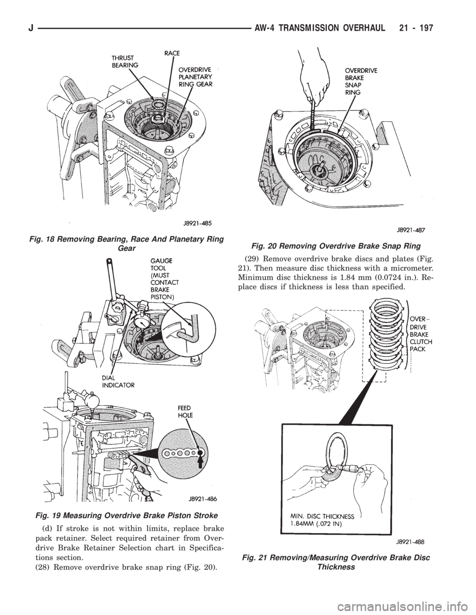
(d) If stroke is not within limits, replace brake
pack retainer. Select required retainer from Over-
drive Brake Retainer Selection chart in Specifica-
tions section.
(28) Remove overdrive brake snap ring (Fig. 20).(29) Remove overdrive brake discs and plates (Fig.
21). Then measure disc thickness with a micrometer.
Minimum disc thickness is 1.84 mm (0.0724 in.). Re-
place discs if thickness is less than specified.
Fig. 19 Measuring Overdrive Brake Piston Stroke
Fig. 18 Removing Bearing, Race And Planetary Ring
GearFig. 20 Removing Overdrive Brake Snap Ring
Fig. 21 Removing/Measuring Overdrive Brake Disc
Thickness
JAW-4 TRANSMISSION OVERHAUL 21 - 197
Page 1309 of 1784
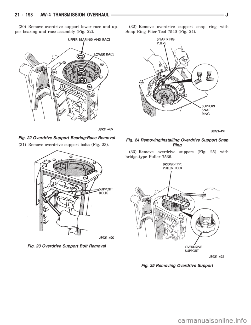
(30) Remove overdrive support lower race and up-
per bearing and race assembly (Fig. 22).
(31) Remove overdrive support bolts (Fig. 23).(32) Remove overdrive support snap ring with
Snap Ring Plier Tool 7540 (Fig. 24).
(33) Remove overdrive support (Fig. 25) with
bridge-type Puller 7536.
Fig. 22 Overdrive Support Bearing/Race Removal
Fig. 23 Overdrive Support Bolt Removal
Fig. 24 Removing/Installing Overdrive Support Snap
Ring
Fig. 25 Removing Overdrive Support
21 - 198 AW-4 TRANSMISSION OVERHAULJ
Page 1310 of 1784
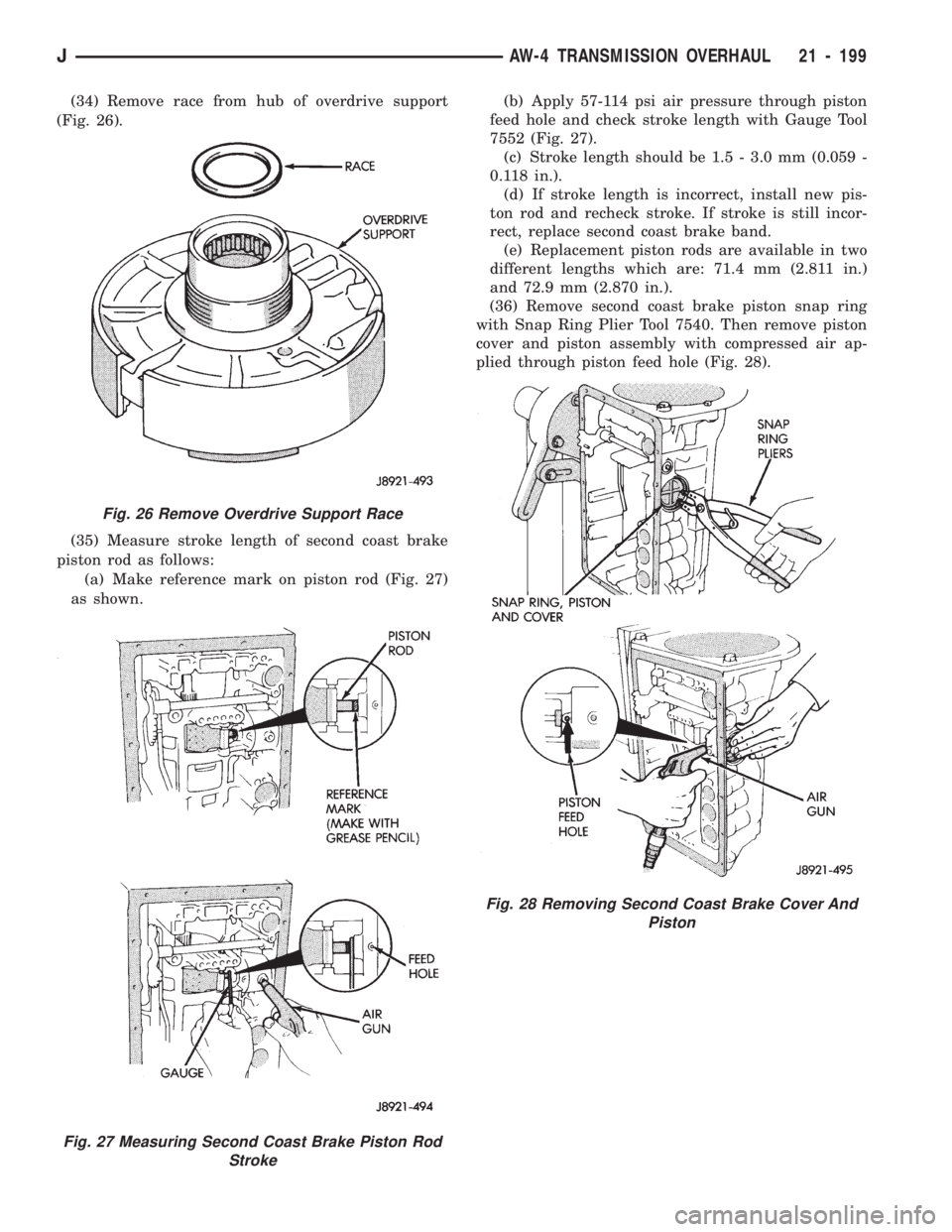
(34) Remove race from hub of overdrive support
(Fig. 26).
(35) Measure stroke length of second coast brake
piston rod as follows:
(a) Make reference mark on piston rod (Fig. 27)
as shown.(b) Apply 57-114 psi air pressure through piston
feed hole and check stroke length with Gauge Tool
7552 (Fig. 27).
(c) Stroke length should be 1.5 - 3.0 mm (0.059 -
0.118 in.).
(d) If stroke length is incorrect, install new pis-
ton rod and recheck stroke. If stroke is still incor-
rect, replace second coast brake band.
(e) Replacement piston rods are available in two
different lengths which are: 71.4 mm (2.811 in.)
and 72.9 mm (2.870 in.).
(36) Remove second coast brake piston snap ring
with Snap Ring Plier Tool 7540. Then remove piston
cover and piston assembly with compressed air ap-
plied through piston feed hole (Fig. 28).
Fig. 27 Measuring Second Coast Brake Piston Rod
Stroke
Fig. 26 Remove Overdrive Support Race
Fig. 28 Removing Second Coast Brake Cover And
Piston
JAW-4 TRANSMISSION OVERHAUL 21 - 199