JEEP CHEROKEE 1994 Service Repair Manual
CHEROKEE 1994
JEEP
JEEP
https://www.carmanualsonline.info/img/16/57038/w960_57038-0.png
JEEP CHEROKEE 1994 Service Repair Manual
Trending: side marker, transmission oil, oil capacity, keyless entry, remote start, brake, drain bolt
Page 1491 of 1784
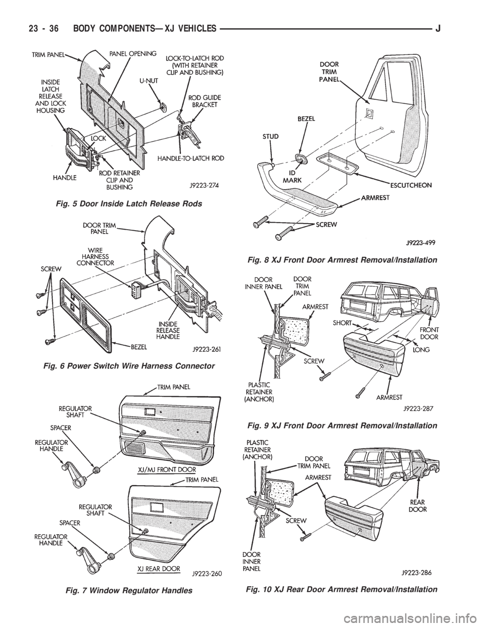
Fig. 5 Door Inside Latch Release Rods
Fig. 6 Power Switch Wire Harness Connector
Fig. 7 Window Regulator Handles
Fig. 8 XJ Front Door Armrest Removal/Installation
Fig. 9 XJ Front Door Armrest Removal/Installation
Fig. 10 XJ Rear Door Armrest Removal/Installation
23 - 36 BODY COMPONENTSÐXJ VEHICLESJ
Page 1492 of 1784
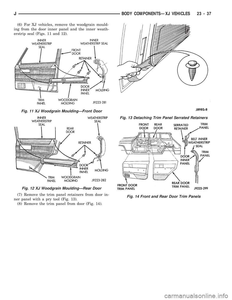
(6) For XJ vehicles, remove the woodgrain mould-
ing from the door inner panel and the inner weath-
erstrip seal (Figs. 11 and 12).
(7) Remove the trim panel retainers from door in-
ner panel with a pry tool (Fig. 13).
(8) Remove the trim panel from door (Fig. 14).
Fig. 11 XJ Woodgrain MouldingÐFront Door
Fig. 12 XJ Woodgrain MouldingÐRear Door
Fig. 13 Detaching Trim Panel Serrated Retainers
Fig. 14 Front and Rear Door Trim Panels
JBODY COMPONENTSÐXJ VEHICLES 23 - 37
Page 1493 of 1784
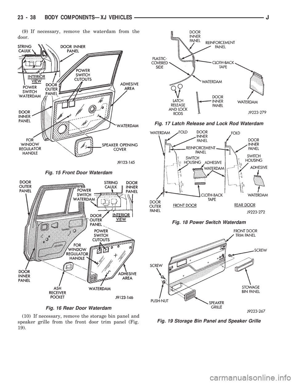
(9) If necessary, remove the waterdam from the
door.
(10) If necessary, remove the storage bin panel and
speaker grille from the front door trim panel (Fig.
19).
Fig. 15 Front Door Waterdam
Fig. 16 Rear Door Waterdam
Fig. 17 Latch Release and Lock Rod Waterdam
Fig. 18 Power Switch Waterdam
Fig. 19 Storage Bin Panel and Speaker Grille
23 - 38 BODY COMPONENTSÐXJ VEHICLESJ
Page 1494 of 1784
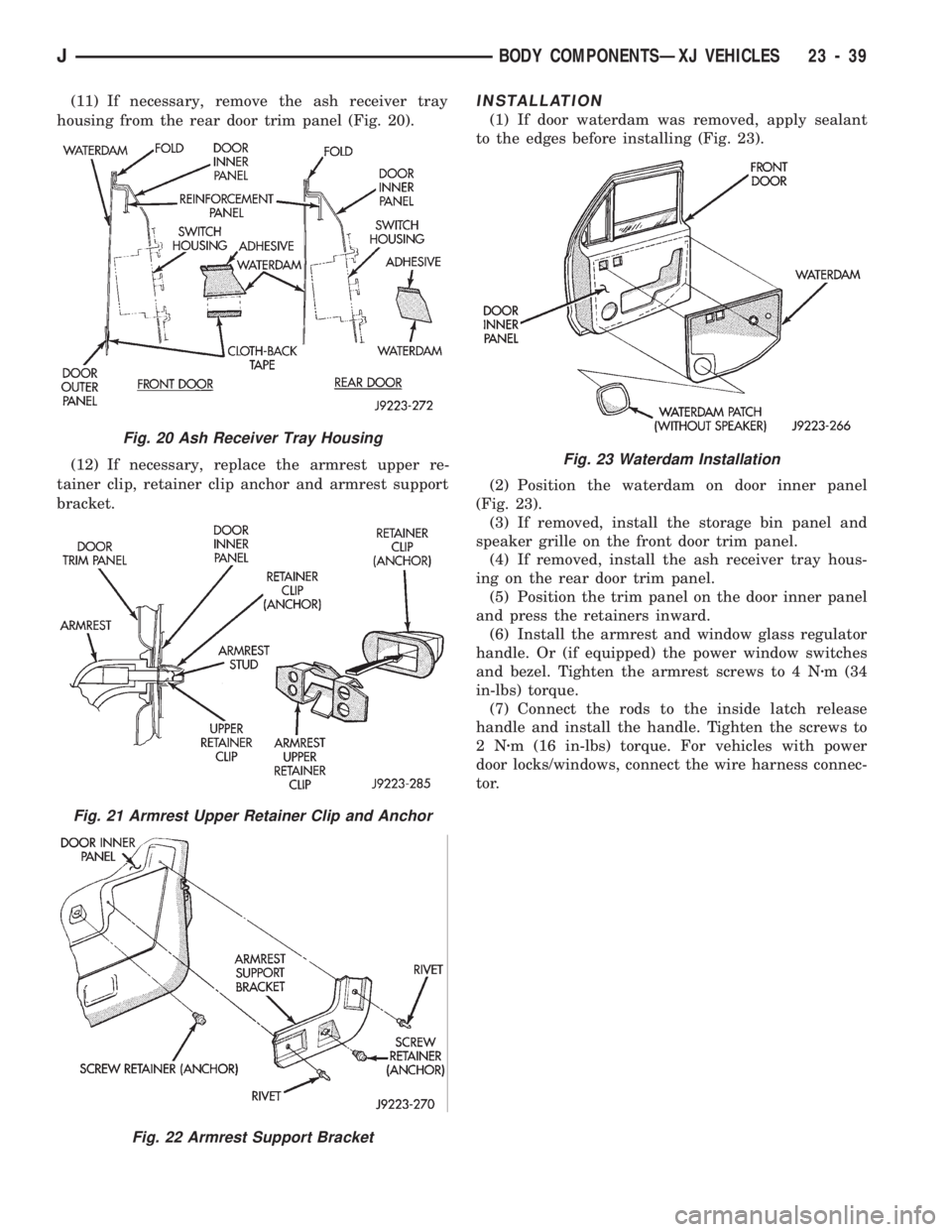
(11) If necessary, remove the ash receiver tray
housing from the rear door trim panel (Fig. 20).
(12) If necessary, replace the armrest upper re-
tainer clip, retainer clip anchor and armrest support
bracket.INSTALLATION
(1) If door waterdam was removed, apply sealant
to the edges before installing (Fig. 23).
(2) Position the waterdam on door inner panel
(Fig. 23).
(3) If removed, install the storage bin panel and
speaker grille on the front door trim panel.
(4) If removed, install the ash receiver tray hous-
ing on the rear door trim panel.
(5) Position the trim panel on the door inner panel
and press the retainers inward.
(6) Install the armrest and window glass regulator
handle. Or (if equipped) the power window switches
and bezel. Tighten the armrest screws to 4 Nzm (34
in-lbs) torque.
(7) Connect the rods to the inside latch release
handle and install the handle. Tighten the screws to
2Nzm (16 in-lbs) torque. For vehicles with power
door locks/windows, connect the wire harness connec-
tor.
Fig. 20 Ash Receiver Tray Housing
Fig. 21 Armrest Upper Retainer Clip and Anchor
Fig. 22 Armrest Support Bracket
Fig. 23 Waterdam Installation
JBODY COMPONENTSÐXJ VEHICLES 23 - 39
Page 1495 of 1784
DOOR REMOVAL/INSTALLATION
REMOVAL
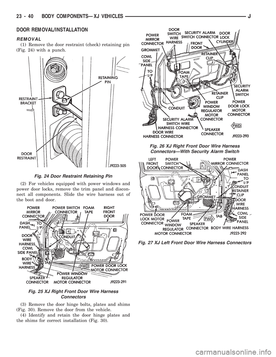
(1) Remove the door restraint (check) retaining pin
(Fig. 24) with a punch.
(2) For vehicles equipped with power windows and
power door locks, remove the trim panel and discon-
nect all components. Slide the wire harness out of
the boot and door.
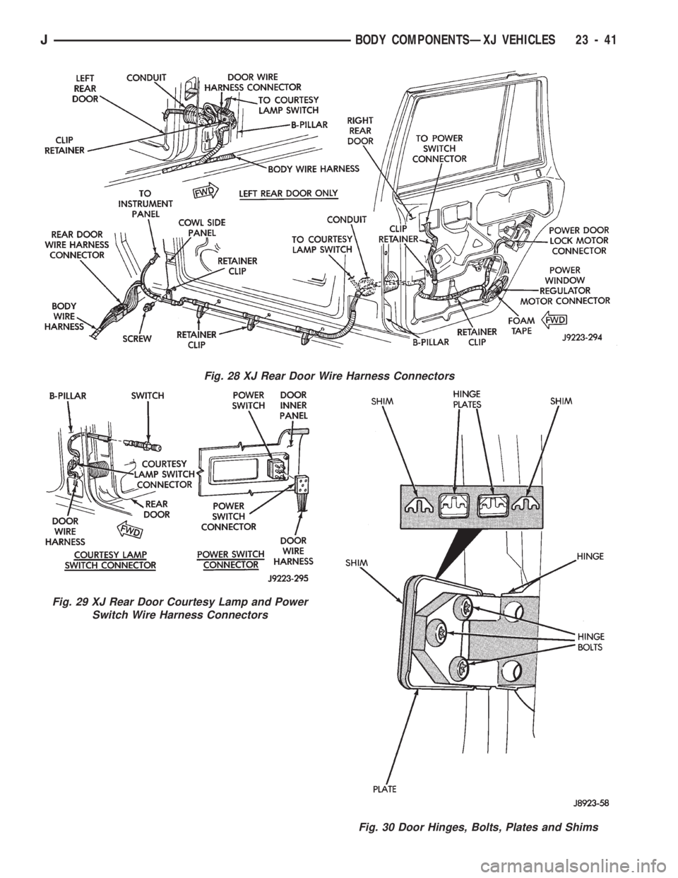
(3) Remove the door hinge bolts, plates and shims
(Fig. 30). Remove the door from the vehicle.
(4) Identify and retain the door hinge plates and
the shims for correct installation (Fig. 30).
Fig. 24 Door Restraint Retaining Pin
Fig. 25 XJ Right Front Door Wire Harness
Connectors
Fig. 26 XJ Right Front Door Wire Harness
ConnectorsÐWith Security Alarm Switch
Fig. 27 XJ Left Front Door Wire Harness Connectors
23 - 40 BODY COMPONENTSÐXJ VEHICLESJ
Page 1496 of 1784
Fig. 28 XJ Rear Door Wire Harness Connectors
Fig. 29 XJ Rear Door Courtesy Lamp and Power
Switch Wire Harness Connectors
Fig. 30 Door Hinges, Bolts, Plates and Shims
JBODY COMPONENTSÐXJ VEHICLES 23 - 41
Page 1497 of 1784
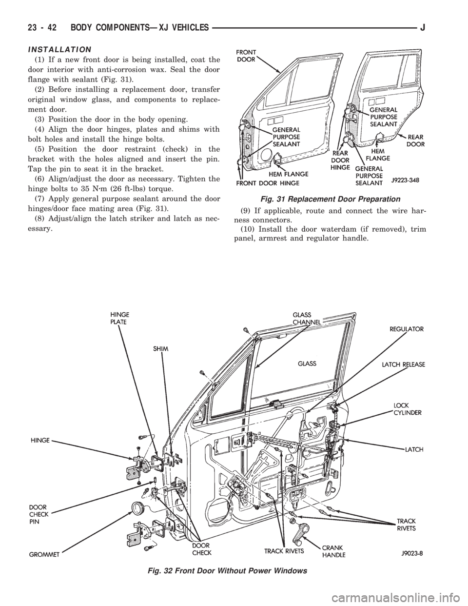
INSTALLATION
(1) If a new front door is being installed, coat the
door interior with anti-corrosion wax. Seal the door
flange with sealant (Fig. 31).
(2) Before installing a replacement door, transfer
original window glass, and components to replace-
ment door.
(3) Position the door in the body opening.
(4) Align the door hinges, plates and shims with
bolt holes and install the hinge bolts.
(5) Position the door restraint (check) in the
bracket with the holes aligned and insert the pin.
Tap the pin to seat it in the bracket.
(6) Align/adjust the door as necessary. Tighten the
hinge bolts to 35 Nzm (26 ft-lbs) torque.
(7) Apply general purpose sealant around the door
hinges/door face mating area (Fig. 31).
(8) Adjust/align the latch striker and latch as nec-
essary.(9) If applicable, route and connect the wire har-
ness connectors.
(10) Install the door waterdam (if removed), trim
panel, armrest and regulator handle.
Fig. 32 Front Door Without Power Windows
Fig. 31 Replacement Door Preparation
23 - 42 BODY COMPONENTSÐXJ VEHICLESJ
Page 1498 of 1784
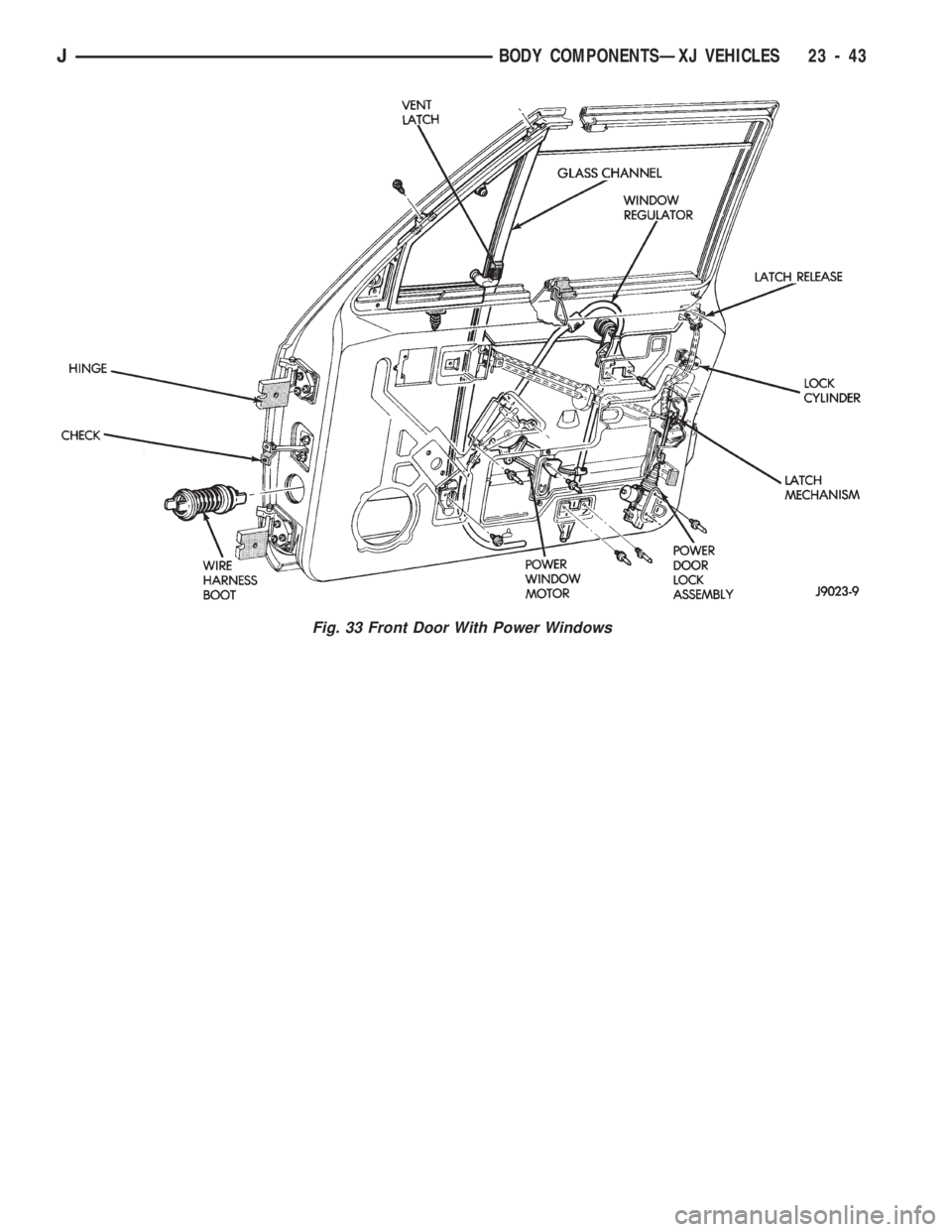
Fig. 33 Front Door With Power Windows
JBODY COMPONENTSÐXJ VEHICLES 23 - 43
Page 1499 of 1784
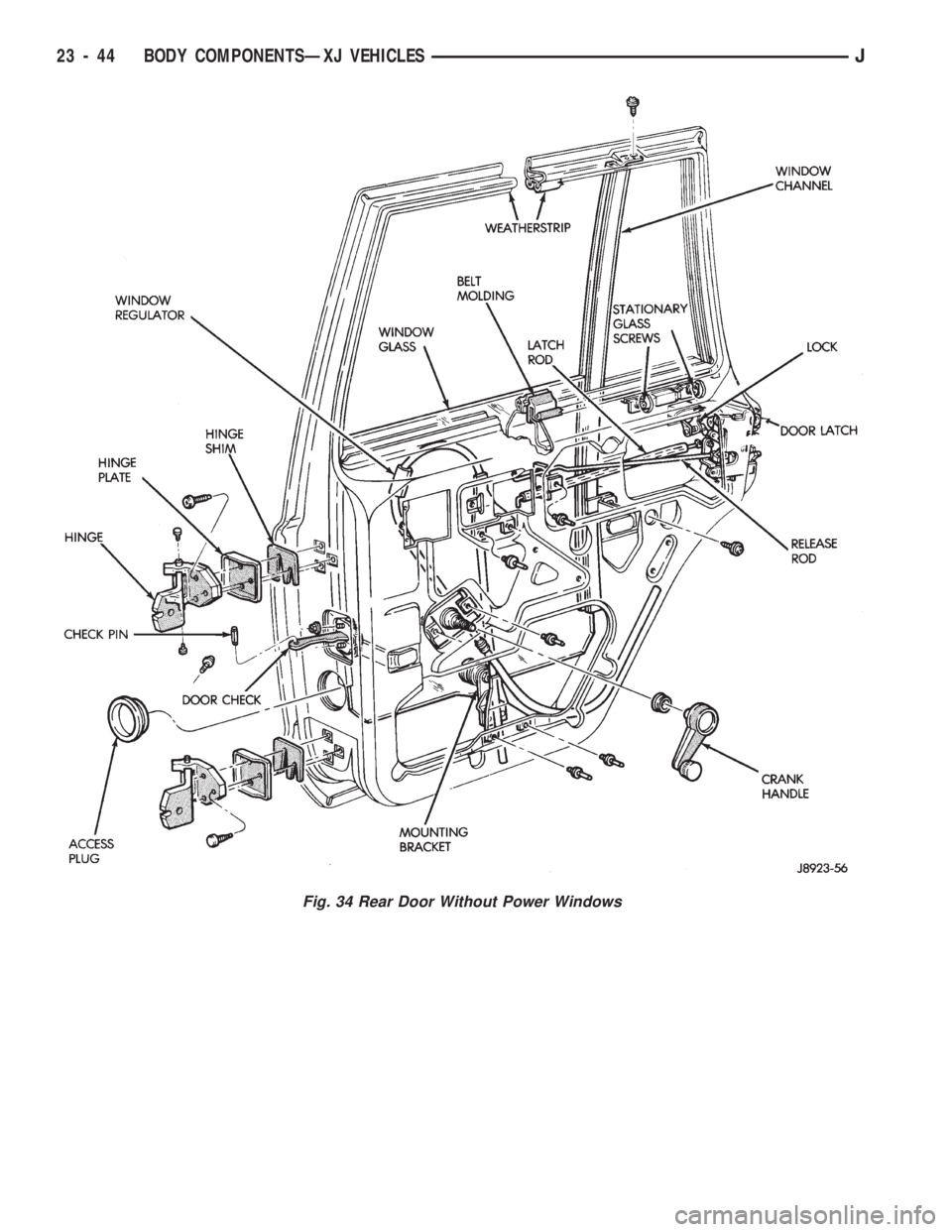
Fig. 34 Rear Door Without Power Windows
23 - 44 BODY COMPONENTSÐXJ VEHICLESJ
Page 1500 of 1784
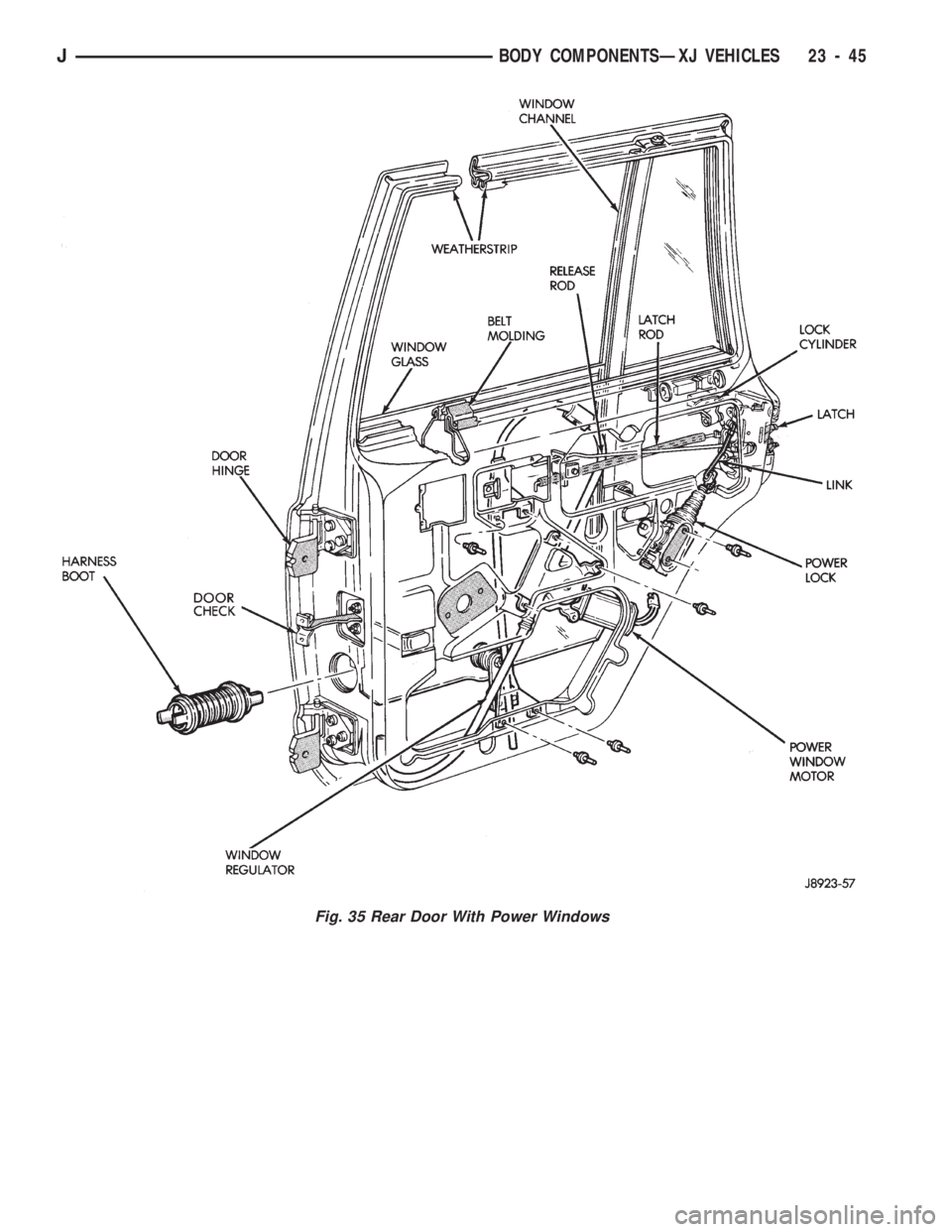
Fig. 35 Rear Door With Power Windows
JBODY COMPONENTSÐXJ VEHICLES 23 - 45
Trending: overheating, wiper fluid, tire type, 4WD, seat adjustment, ignition, charging
