JEEP CHEROKEE 1994 Service Repair Manual
Manufacturer: JEEP, Model Year: 1994, Model line: CHEROKEE, Model: JEEP CHEROKEE 1994Pages: 1784, PDF Size: 77.09 MB
Page 1521 of 1784
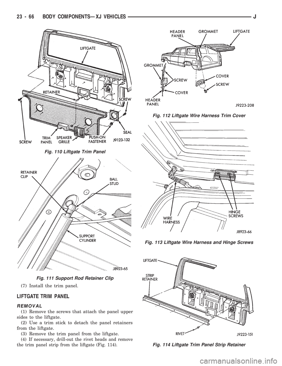
(7) Install the trim panel.
LIFTGATE TRIM PANEL
REMOVAL
(1) Remove the screws that attach the panel upper
sides to the liftgate.
(2) Use a trim stick to detach the panel retainers
from the liftgate.
(3) Remove the trim panel from the liftgate.
(4) If necessary, drill-out the rivet heads and remove
the trim panel strip from the liftgate (Fig. 114).
Fig. 112 Liftgate Wire Harness Trim Cover
Fig. 113 Liftgate Wire Harness and Hinge Screws
Fig. 114 Liftgate Trim Panel Strip Retainer
Fig. 110 Liftgate Trim Panel
Fig. 111 Support Rod Retainer Clip
23 - 66 BODY COMPONENTSÐXJ VEHICLESJ
Page 1522 of 1784
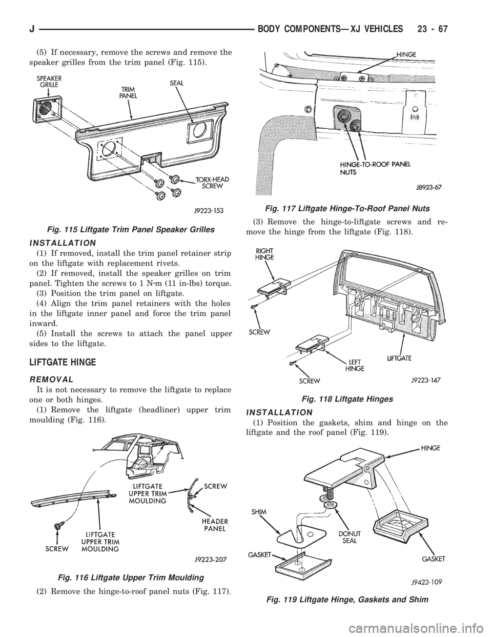
(5) If necessary, remove the screws and remove the
speaker grilles from the trim panel (Fig. 115).
INSTALLATION
(1) If removed, install the trim panel retainer strip
on the liftgate with replacement rivets.
(2) If removed, install the speaker grilles on trim
panel. Tighten the screws to 1 Nzm (11 in-lbs) torque.
(3) Position the trim panel on liftgate.
(4) Align the trim panel retainers with the holes
in the liftgate inner panel and force the trim panel
inward.
(5) Install the screws to attach the panel upper
sides to the liftgate.
LIFTGATE HINGE
REMOVAL
It is not necessary to remove the liftgate to replace
one or both hinges.
(1) Remove the liftgate (headliner) upper trim
moulding (Fig. 116).
(2) Remove the hinge-to-roof panel nuts (Fig. 117).(3) Remove the hinge-to-liftgate screws and re-
move the hinge from the liftgate (Fig. 118).
INSTALLATION
(1) Position the gaskets, shim and hinge on the
liftgate and the roof panel (Fig. 119).
Fig. 115 Liftgate Trim Panel Speaker Grilles
Fig. 116 Liftgate Upper Trim Moulding
Fig. 117 Liftgate Hinge-To-Roof Panel Nuts
Fig. 118 Liftgate Hinges
Fig. 119 Liftgate Hinge, Gaskets and Shim
JBODY COMPONENTSÐXJ VEHICLES 23 - 67
Page 1523 of 1784
(2) Install and tighten hinge-to-roof panel nuts to 9
Nzm (7 ft-lbs) torque.
(3) Install the liftgate-to-hinge screws. Tighten
screws to 9 Nzm (7 ft-lbs) torque.
(4) Install the liftgate (headliner) upper trim moul-
ding (Fig. 111).
LIFTGATE LATCH/KEY LOCK CYLINDER/STRIKER
REMOVAL
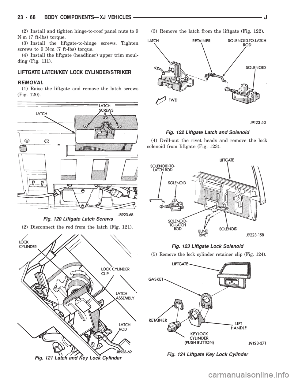
(1) Raise the liftgate and remove the latch screws
(Fig. 120).
(2) Disconnect the rod from the latch (Fig. 121).(3) Remove the latch from the liftgate (Fig. 122).
(4) Drill-out the rivet heads and remove the lock
solenoid from liftgate (Fig. 123).
(5) Remove the lock cylinder retainer clip (Fig. 124).
Fig. 121 Latch and Key Lock Cylinder
Fig. 122 Liftgate Latch and Solenoid
Fig. 123 Liftgate Lock Solenoid
Fig. 124 Liftgate Key Lock Cylinder
Fig. 120 Liftgate Latch Screws
23 - 68 BODY COMPONENTSÐXJ VEHICLESJ
Page 1524 of 1784
(6) Remove the key lock cylinder.
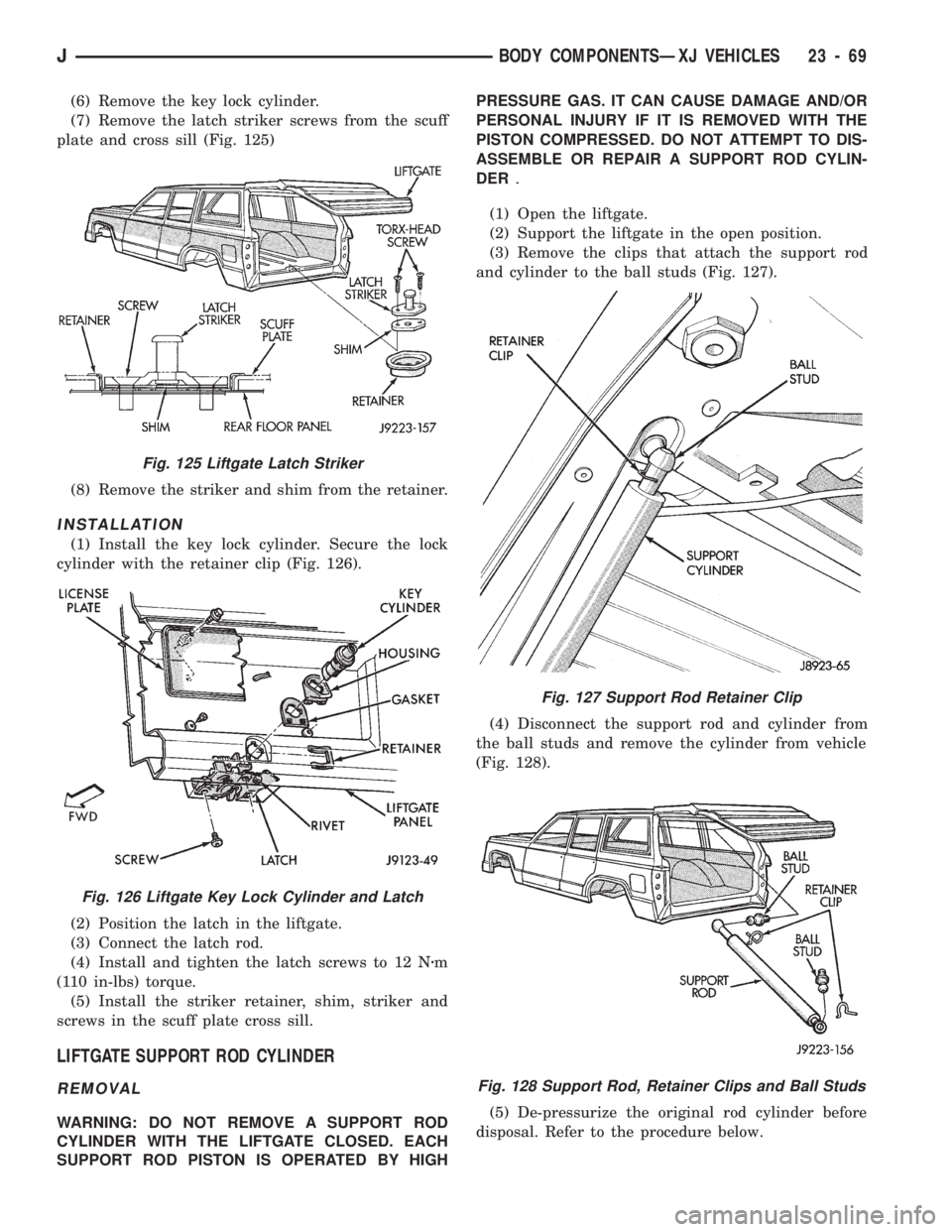
(7) Remove the latch striker screws from the scuff
plate and cross sill (Fig. 125)
(8) Remove the striker and shim from the retainer.
INSTALLATION
(1) Install the key lock cylinder. Secure the lock
cylinder with the retainer clip (Fig. 126).
(2) Position the latch in the liftgate.
(3) Connect the latch rod.
(4) Install and tighten the latch screws to 12 Nzm
(110 in-lbs) torque.
(5) Install the striker retainer, shim, striker and
screws in the scuff plate cross sill.
LIFTGATE SUPPORT ROD CYLINDER
REMOVAL
WARNING: DO NOT REMOVE A SUPPORT ROD
CYLINDER WITH THE LIFTGATE CLOSED. EACH
SUPPORT ROD PISTON IS OPERATED BY HIGHPRESSURE GAS. IT CAN CAUSE DAMAGE AND/OR
PERSONAL INJURY IF IT IS REMOVED WITH THE
PISTON COMPRESSED. DO NOT ATTEMPT TO DIS-
ASSEMBLE OR REPAIR A SUPPORT ROD CYLIN-
DER.
(1) Open the liftgate.
(2) Support the liftgate in the open position.
(3) Remove the clips that attach the support rod
and cylinder to the ball studs (Fig. 127).
(4) Disconnect the support rod and cylinder from
the ball studs and remove the cylinder from vehicle
(Fig. 128).
(5) De-pressurize the original rod cylinder before
disposal. Refer to the procedure below.
Fig. 127 Support Rod Retainer Clip
Fig. 128 Support Rod, Retainer Clips and Ball Studs
Fig. 125 Liftgate Latch Striker
Fig. 126 Liftgate Key Lock Cylinder and Latch
JBODY COMPONENTSÐXJ VEHICLES 23 - 69
Page 1525 of 1784
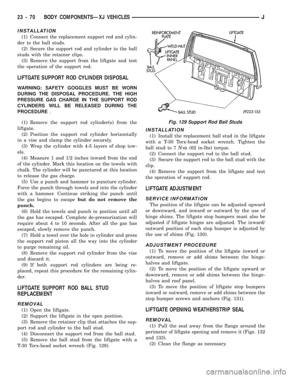
INSTALLATION
(1) Connect the replacement support rod and cylin-
der to the ball studs.
(2) Secure the support rod and cylinder to the ball
studs with the retainer clips.
(3) Remove the support from the liftgate and test
the operation of the support rod.
LIFTGATE SUPPORT ROD CYLINDER DISPOSAL
WARNING: SAFETY GOGGLES MUST BE WORN
DURING THE DISPOSAL PROCEDURE. THE HIGH
PRESSURE GAS CHARGE IN THE SUPPORT ROD
CYLINDERS WILL BE RELEASED DURING THE
PROCEDURE.
(1) Remove the support rod cylinder(s) from the
liftgate.
(2) Position the support rod cylinder horizontally
in a vise and clamp the cylinder securely.
(3) Wrap the cylinder with 4-5 layers of shop tow-
els.
(4) Measure 1 and 1/2 inches inward from the end
of the cylinder. Mark this location on the towels with
chalk. The cylinder will be punctured at this location
to release the gas charge.
(5) Use a punch and hammer to puncture cylinder.
Force the punch through towels and into the cylinder
with a hammer. Continue striking the punch until
the gas begins to escapebut do not remove the
punch.
(6) Hold the towels and punch in position until all
the gas has escaped. Complete de-pressurization will
require about 4 to 10 seconds. After all the gas has
escaped, slowly remove the punch.
(7) Hold a towel over the hole in cylinder and press
the support rod piston all the way into the cylinder
to purge remaining oil.
(8) Remove the support rod cylinder from the vise
and discard it.
(9) If both support rod cylinders are being re-
placed, repeat this procedure for the remaining cylin-
der.
LIFTGATE SUPPORT ROD BALL STUD
REPLACEMENT
REMOVAL
(1) Open the liftgate.
(2) Support the liftgate in the open position.
(3) Remove the retainer clip that attaches the sup-
port rod and cylinder to the ball stud.
(4) Disconnect the support rod from the ball stud.
(5) Remove the ball stud from the liftgate with a
T-30 Torx-head socket wrench (Fig. 129).
INSTALLATION
(1) Install the replacement ball stud in the liftgate
with a T-30 Torx-head socket wrench. Tighten the
ball stud to 7 Nzm (62 in-lbs) torque.
(2) Connect the support rod to the ball stud.
(3) Secure the support rod to the ball stud with the
clip.
(4) Remove the support from the liftgate and test
the operation of support rod.
LIFTGATE ADJUSTMENT
SERVICE INFORMATION
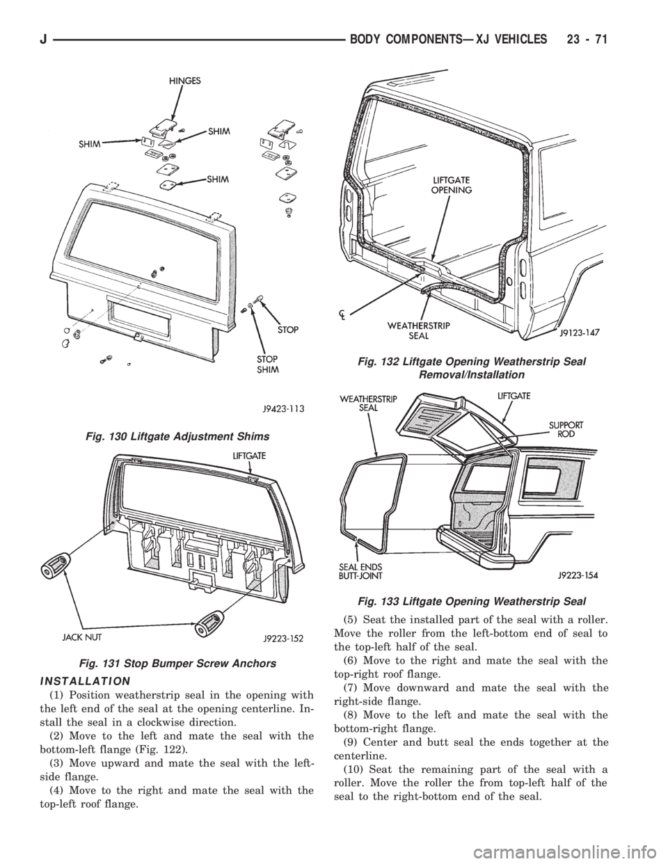
The position of the liftgate can be adjusted upward
or downward, and inward or outward by the use of
hinge shims. The liftgate stop bumpers must also be
adjusted if liftgate hinges are adjusted. The inward/
outward position of each stop bumper is adjusted by
the use of shims (Fig. 130).
ADJUSTMENT PROCEDURE
(1) To move the position of the liftgate inward or
outward, remove or add shims between the hinge-
halves and liftgate.
(2) To move the position of the liftgate upward or
downward, remove or add shims between the hinge-
halves and roof panel.
(3) To move the position of liftgate stop bumpers
inward or outward, remove or add shims between the
stop bumper screws and anchors (Fig. 131).
LIFTGATE OPENING WEATHERSTRIP SEAL
REMOVAL
(1) Pull the seal away from the flange around the
perimeter of liftgate opening and remove it (Figs. 132
and 133).
(2) Clean the flange as necessary.
Fig. 129 Support Rod Ball Studs
23 - 70 BODY COMPONENTSÐXJ VEHICLESJ
Page 1526 of 1784
INSTALLATION
(1) Position weatherstrip seal in the opening with
the left end of the seal at the opening centerline. In-
stall the seal in a clockwise direction.
(2) Move to the left and mate the seal with the
bottom-left flange (Fig. 122).
(3) Move upward and mate the seal with the left-
side flange.
(4) Move to the right and mate the seal with the
top-left roof flange.(5) Seat the installed part of the seal with a roller.
Move the roller from the left-bottom end of seal to
the top-left half of the seal.
(6) Move to the right and mate the seal with the
top-right roof flange.
(7) Move downward and mate the seal with the
right-side flange.
(8) Move to the left and mate the seal with the
bottom-right flange.
(9) Center and butt seal the ends together at the
centerline.
(10) Seat the remaining part of the seal with a
roller. Move the roller the from top-left half of the
seal to the right-bottom end of the seal.
Fig. 130 Liftgate Adjustment Shims
Fig. 131 Stop Bumper Screw Anchors
Fig. 132 Liftgate Opening Weatherstrip Seal
Removal/Installation
Fig. 133 Liftgate Opening Weatherstrip Seal
JBODY COMPONENTSÐXJ VEHICLES 23 - 71
Page 1527 of 1784
LIFTGATE LICENSE PLATE LAMP HOUSING
REMOVAL
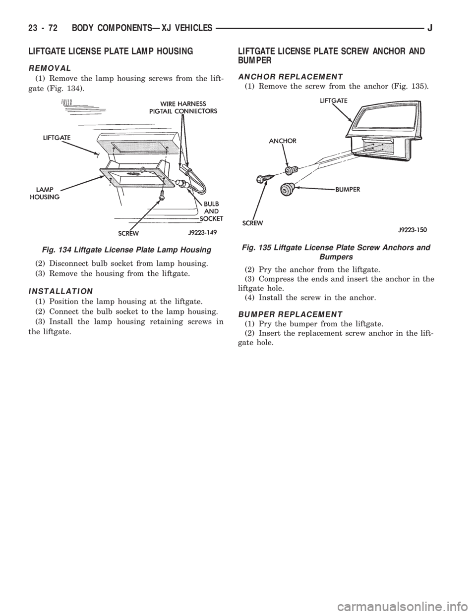
(1) Remove the lamp housing screws from the lift-
gate (Fig. 134).
(2) Disconnect bulb socket from lamp housing.
(3) Remove the housing from the liftgate.
INSTALLATION
(1) Position the lamp housing at the liftgate.
(2) Connect the bulb socket to the lamp housing.
(3) Install the lamp housing retaining screws in
the liftgate.
LIFTGATE LICENSE PLATE SCREW ANCHOR AND
BUMPER
ANCHOR REPLACEMENT
(1) Remove the screw from the anchor (Fig. 135).
(2) Pry the anchor from the liftgate.
(3) Compress the ends and insert the anchor in the
liftgate hole.
(4) Install the screw in the anchor.
BUMPER REPLACEMENT
(1) Pry the bumper from the liftgate.
(2) Insert the replacement screw anchor in the lift-
gate hole.
Fig. 134 Liftgate License Plate Lamp HousingFig. 135 Liftgate License Plate Screw Anchors and
Bumpers
23 - 72 BODY COMPONENTSÐXJ VEHICLESJ
Page 1528 of 1784
FIXED WINDOW GLASS
INDEX
page page
Fixed Glass Water Leak Detection and Repair . . 83
Interior Rearview Mirror.................... 74
Interior Rearview Mirror Support Bracket
Replacement.......................... 75
Liftgate Window GlassÐXJ Vehicles.......... 81
Rear Quarter Vent Window GlassÐXJ Vehicles . 80Rear Quarter Window Glass/Rear Quarter
Plastic Insert ÐXJ Vehicles............... 80
Service Information....................... 73
Windshield Glass Replacement.............. 75
Windshield Reveal Moulding................ 73
Windshield Service Information.............. 75
SERVICE INFORMATION
The following service procedures include removal
and installation of the:
²windshield reveal moulding,
²interior rearview mirror,
²windshield glass (using both the short and the ex-
tended installation method),
²rear quarter vent window glass,
²rear quarter window glass,
²liftgate window glass,
²cab rear window, and
²leak detection and repair.
WINDSHIELD REVEAL MOULDING
REMOVAL
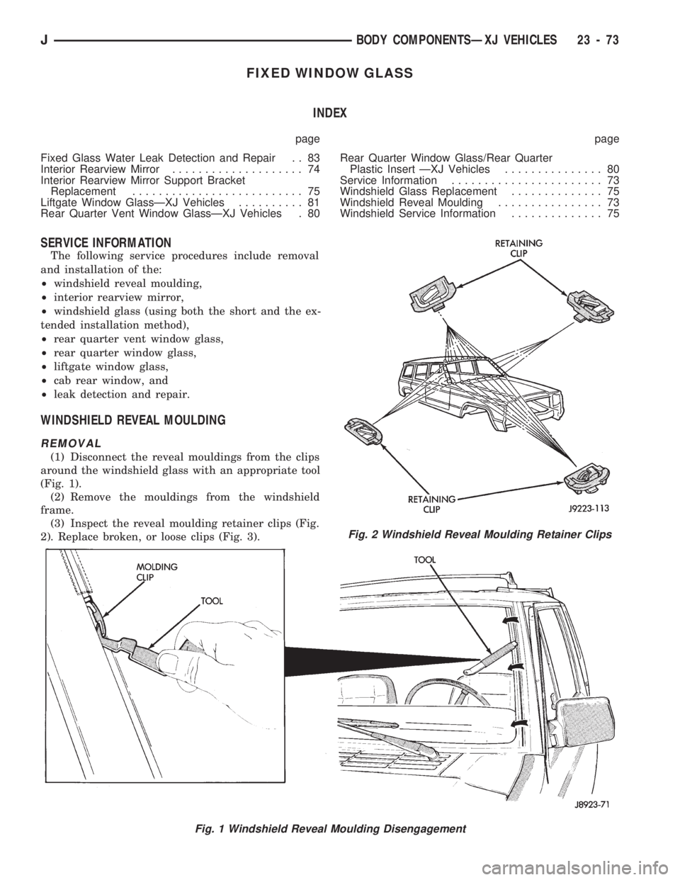
(1) Disconnect the reveal mouldings from the clips
around the windshield glass with an appropriate tool
(Fig. 1).
(2) Remove the mouldings from the windshield
frame.
(3) Inspect the reveal moulding retainer clips (Fig.
2). Replace broken, or loose clips (Fig. 3).
Fig. 1 Windshield Reveal Moulding Disengagement
Fig. 2 Windshield Reveal Moulding Retainer Clips
JBODY COMPONENTSÐXJ VEHICLES 23 - 73
Page 1529 of 1784
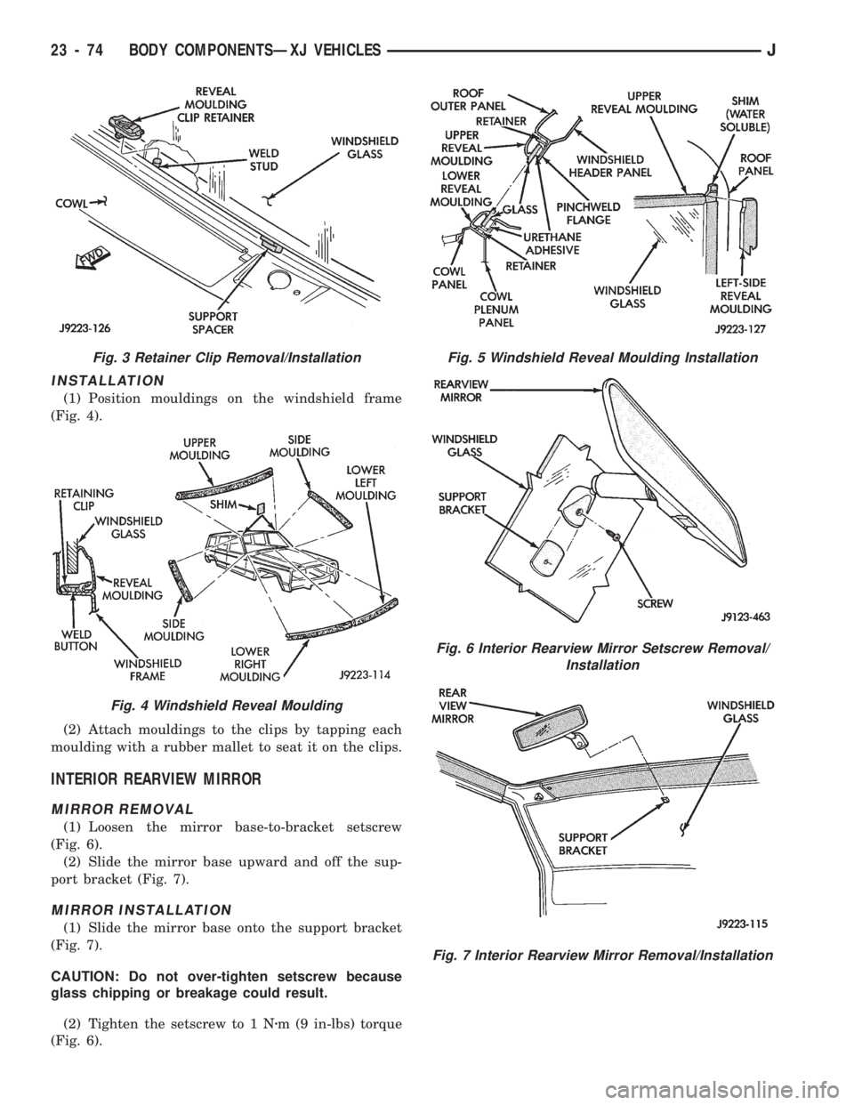
INSTALLATION
(1) Position mouldings on the windshield frame
(Fig. 4).
(2) Attach mouldings to the clips by tapping each
moulding with a rubber mallet to seat it on the clips.
INTERIOR REARVIEW MIRROR
MIRROR REMOVAL
(1) Loosen the mirror base-to-bracket setscrew
(Fig. 6).
(2) Slide the mirror base upward and off the sup-
port bracket (Fig. 7).
MIRROR INSTALLATION
(1) Slide the mirror base onto the support bracket
(Fig. 7).
CAUTION: Do not over-tighten setscrew because
glass chipping or breakage could result.
(2) Tighten the setscrew to 1 Nzm (9 in-lbs) torque
(Fig. 6).
Fig. 5 Windshield Reveal Moulding Installation
Fig. 6 Interior Rearview Mirror Setscrew Removal/
Installation
Fig. 7 Interior Rearview Mirror Removal/Installation
Fig. 3 Retainer Clip Removal/Installation
Fig. 4 Windshield Reveal Moulding
23 - 74 BODY COMPONENTSÐXJ VEHICLESJ
Page 1530 of 1784
INTERIOR REARVIEW MIRROR SUPPORT
BRACKET REPLACEMENT
PREPARATION
(1) Mark reference lines for the mirror support
bracket on the outside of windshield glass with a wax
pencil.
(2) If the vinyl pad remained on the windshield
glass, soften and remove it with a heat gun.
(3) Clean the support bracket surface area on the
glass. Use a mild abrasive cleaning powder on a cloth
saturated with isopropyl (rubbing) alcohol.
(4) Lightly sand the contact surface on the support
bracket with fine grit sandpaper. Wipe bracket con-
tact surface clean with a paper towel and alcohol.
INSTALLATION
(1) Apply adhesive to the act surface on the sup-
port bracket according as follows:
²crush the vial in the plastic housing of the accel-
erator to saturate the felt applicator;
²remove the paper sleeve;
²apply a generous amount of accelerator to the con-
tact surface on the mirror support bracket;
²do not touch the support bracket contact surface
after the accelerator has been applied.
²allow the accelerator to dry for at least five min-
utes; and
(2) Apply accelerator to the support bracket con-
tact surface on the windshield glass. Allow the accel-
erator to dry for one minute.
(3) Install the mirror bracket on the windshield
glass follows:
²apply one drop of adhesive at the center of support
bracket contact surface on windshield glass;
²immediately apply an even coat of adhesive to the
contact surface on the support bracket;
²align the support bracket with the position refer-
ence lines on the windshield glass, then
²press and hold the support bracket in-place for at
least one minute.
Ensure that the mirror support bracket is
correctly aligned because the adhesive will
cure rapidly.
(4) Allow the adhesive to cure for 8-10 minutes,
then remove any residue adhesive with an alcohol-
dampened cloth.
(5) Allow the adhesive to cure for an additional
8-10 minutes before installing the mirror base on the
support bracket.
WINDSHIELD SERVICE INFORMATION
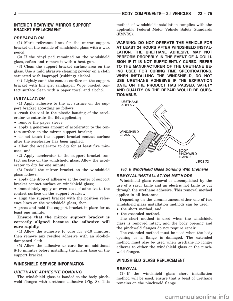
URETHANE ADHESIVE BONDING
The windshield glass is bonded to the body pinch-
weld flanges with urethane adhesive (Fig. 8). Thismethod of windshield installation complies with the
applicable Federal Motor Vehicle Safety Standards
(FMVSS).
WARNING: DO NOT OPERATE THE VEHICLE FOR
AT LEAST 24 HOURS AFTER WINDSHIELD INSTAL-
LATION. THE URETHANE ADHESIVE MAY NOT
PERFORM PROPERLY IN THE EVENT OF A COLLI-
SION IF IT IS NOT SUFFICIENTLY CURED. REFER
TO THE MANUFACTURER OF THE URETHANE BE-
ING USED FOR CURING TIME SPECIFICATIONS.
WHEN INSTALLING THE WINDSHIELD, DO NOT
USE URETHANE ADHESIVE IF THE EXPIRATION
DATE ON THE PRODUCT HAS PASSED. SAFETY
AND QUALITY ON THE REPAIR WOULD BE QUES-
TIONABLE.
REMOVAL/INSTALLATION METHODS
Windshield glass removal is accomplished by the
use of a razor knife and an electric hot knife to cut
through the urethane adhesive. This removal method
applies in all instances.
Depending on the circumstances, either one of two
windshield glass installation methods can be used:
²the short method, and
²the extended method.
The short method is used when the windshield
glass is removed intact, and the body opening and
the pinchweld flanges do not require repair.
The extended method must be used when the body
opening or a flange is damaged. The extended
method must also be used when urethane no longer
adheres to either the windshield glass or the pinch-
weld flanges.
WINDSHIELD GLASS REPLACEMENT
REMOVAL
(1) If the windshield glass short installation
method will be used, ensure that a bead of urethane
remains on the pinchweld flange.
Fig. 8 Windshield Glass Bonding With Urethane
JBODY COMPONENTSÐXJ VEHICLES 23 - 75