JEEP CHEROKEE 1994 Service Repair Manual
Manufacturer: JEEP, Model Year: 1994, Model line: CHEROKEE, Model: JEEP CHEROKEE 1994Pages: 1784, PDF Size: 77.09 MB
Page 1561 of 1784
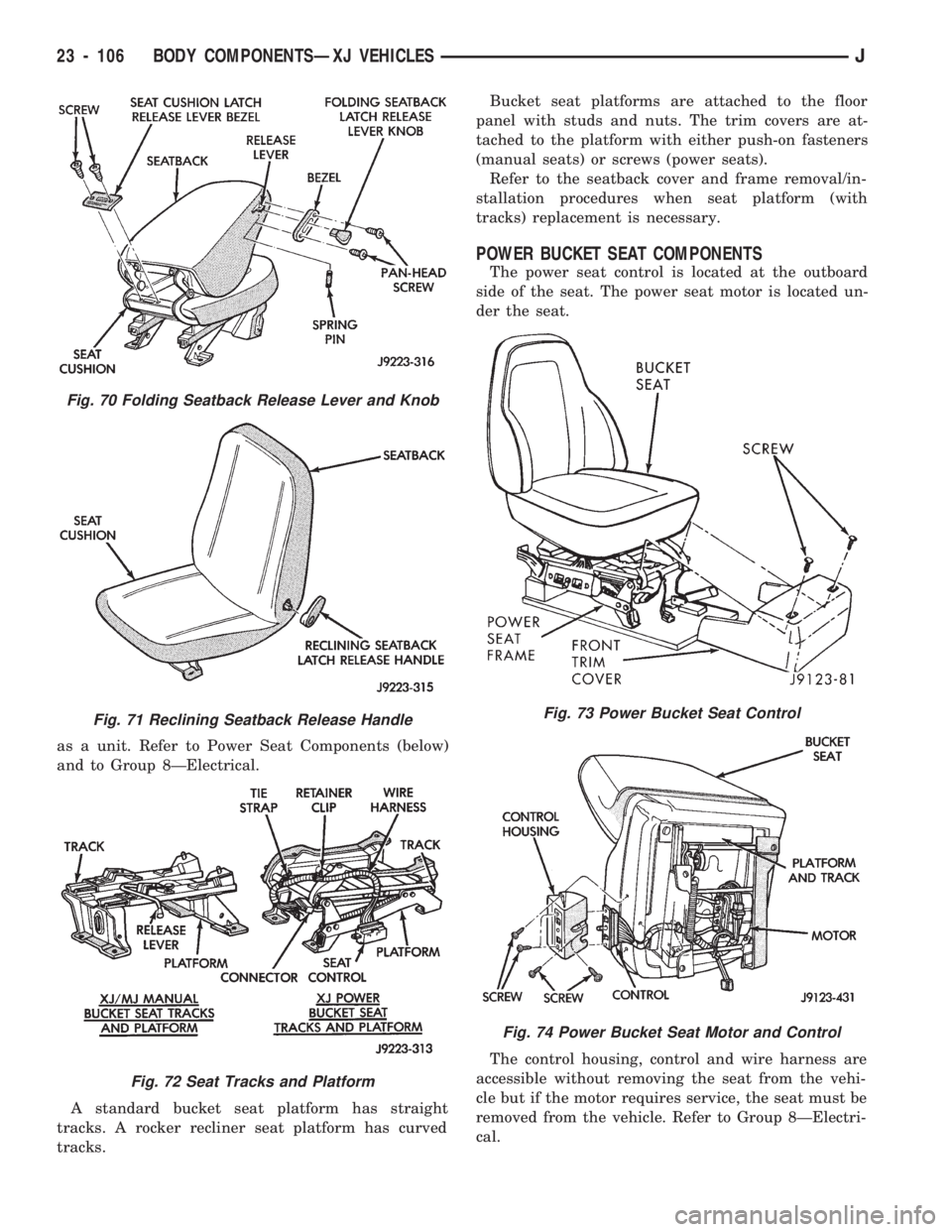
as a unit. Refer to Power Seat Components (below)
and to Group 8ÐElectrical.
A standard bucket seat platform has straight
tracks. A rocker recliner seat platform has curved
tracks.Bucket seat platforms are attached to the floor
panel with studs and nuts. The trim covers are at-
tached to the platform with either push-on fasteners
(manual seats) or screws (power seats).
Refer to the seatback cover and frame removal/in-
stallation procedures when seat platform (with
tracks) replacement is necessary.
POWER BUCKET SEAT COMPONENTS
The power seat control is located at the outboard
side of the seat. The power seat motor is located un-
der the seat.
The control housing, control and wire harness are
accessible without removing the seat from the vehi-
cle but if the motor requires service, the seat must be
removed from the vehicle. Refer to Group 8ÐElectri-
cal.
Fig. 70 Folding Seatback Release Lever and Knob
Fig. 71 Reclining Seatback Release Handle
Fig. 72 Seat Tracks and Platform
Fig. 73 Power Bucket Seat Control
Fig. 74 Power Bucket Seat Motor and Control
23 - 106 BODY COMPONENTSÐXJ VEHICLESJ
Page 1562 of 1784
REAR SEAT CUSHIONÐXJ VEHICLES
REMOVAL
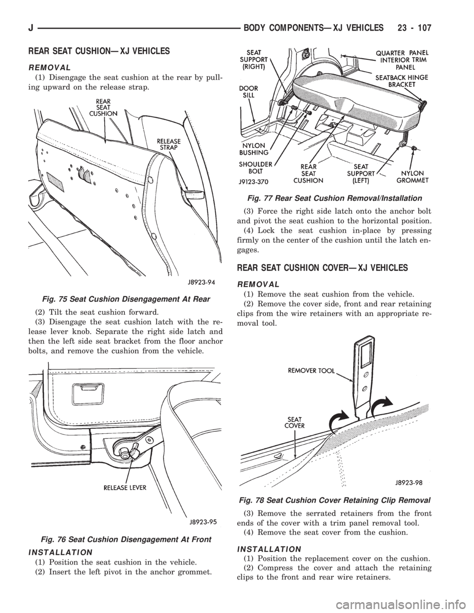
(1) Disengage the seat cushion at the rear by pull-
ing upward on the release strap.
(2) Tilt the seat cushion forward.
(3) Disengage the seat cushion latch with the re-
lease lever knob. Separate the right side latch and
then the left side seat bracket from the floor anchor
bolts, and remove the cushion from the vehicle.
INSTALLATION
(1) Position the seat cushion in the vehicle.
(2) Insert the left pivot in the anchor grommet.(3) Force the right side latch onto the anchor bolt
and pivot the seat cushion to the horizontal position.
(4) Lock the seat cushion in-place by pressing
firmly on the center of the cushion until the latch en-
gages.
REAR SEAT CUSHION COVERÐXJ VEHICLES
REMOVAL
(1) Remove the seat cushion from the vehicle.
(2) Remove the cover side, front and rear retaining
clips from the wire retainers with an appropriate re-
moval tool.
(3) Remove the serrated retainers from the front
ends of the cover with a trim panel removal tool.
(4) Remove the seat cover from the cushion.
INSTALLATION
(1) Position the replacement cover on the cushion.
(2) Compress the cover and attach the retaining
clips to the front and rear wire retainers.
Fig. 75 Seat Cushion Disengagement At Rear
Fig. 76 Seat Cushion Disengagement At Front
Fig. 77 Rear Seat Cushion Removal/Installation
Fig. 78 Seat Cushion Cover Retaining Clip Removal
JBODY COMPONENTSÐXJ VEHICLES 23 - 107
Page 1563 of 1784
(3) Install the serrated retainers at the ends of the
cover.
(4) Install the seat cushion in the vehicle. If neces-
sary, refer to the installation procedure.
REAR SEAT CUSHION RECONDITIONINGÐXJ
VEHICLES
ASSEMBLY
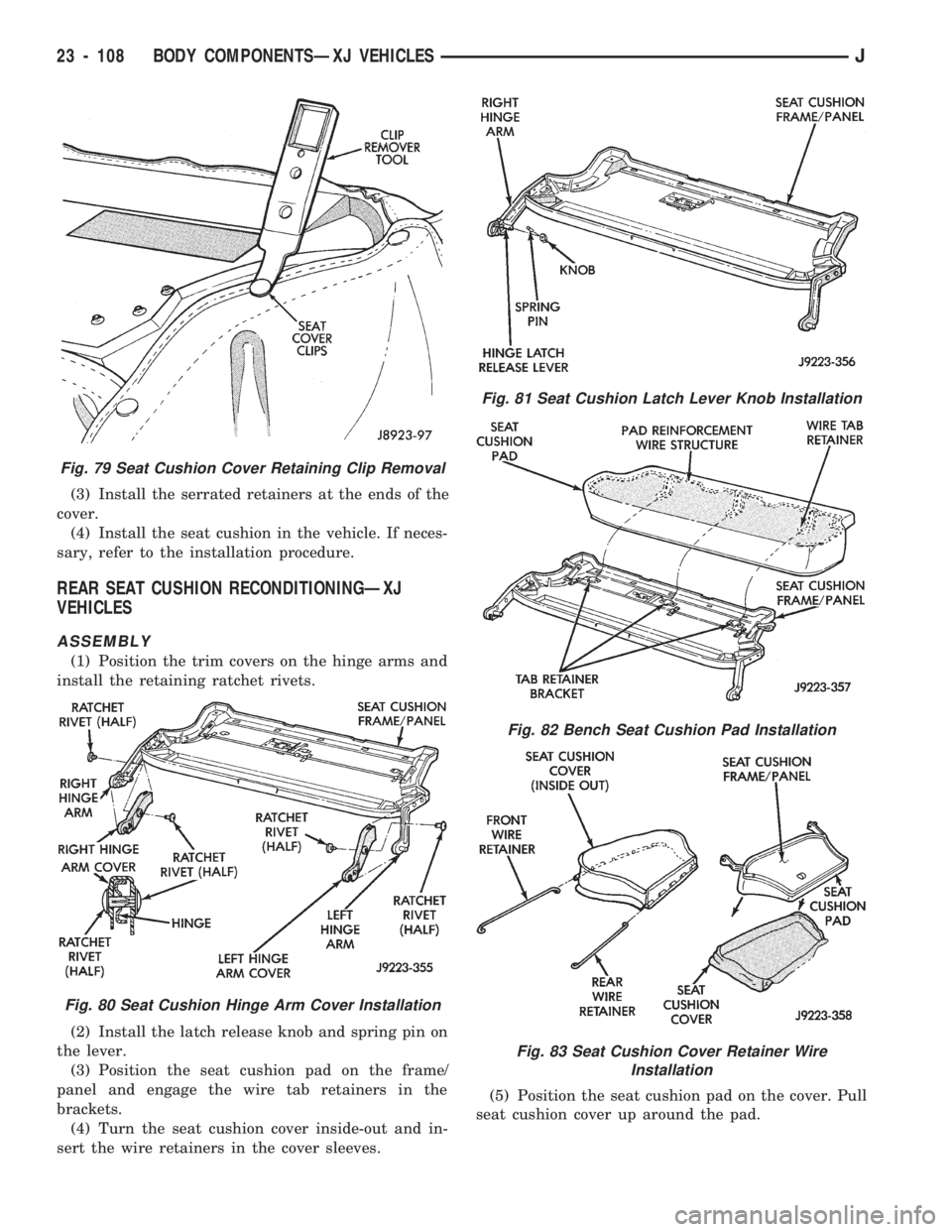
(1) Position the trim covers on the hinge arms and
install the retaining ratchet rivets.
(2) Install the latch release knob and spring pin on
the lever.
(3) Position the seat cushion pad on the frame/
panel and engage the wire tab retainers in the
brackets.
(4) Turn the seat cushion cover inside-out and in-
sert the wire retainers in the cover sleeves.(5) Position the seat cushion pad on the cover. Pull
seat cushion cover up around the pad.
Fig. 79 Seat Cushion Cover Retaining Clip Removal
Fig. 80 Seat Cushion Hinge Arm Cover Installation
Fig. 81 Seat Cushion Latch Lever Knob Installation
Fig. 82 Bench Seat Cushion Pad Installation
Fig. 83 Seat Cushion Cover Retainer Wire
Installation
23 - 108 BODY COMPONENTSÐXJ VEHICLESJ
Page 1564 of 1784
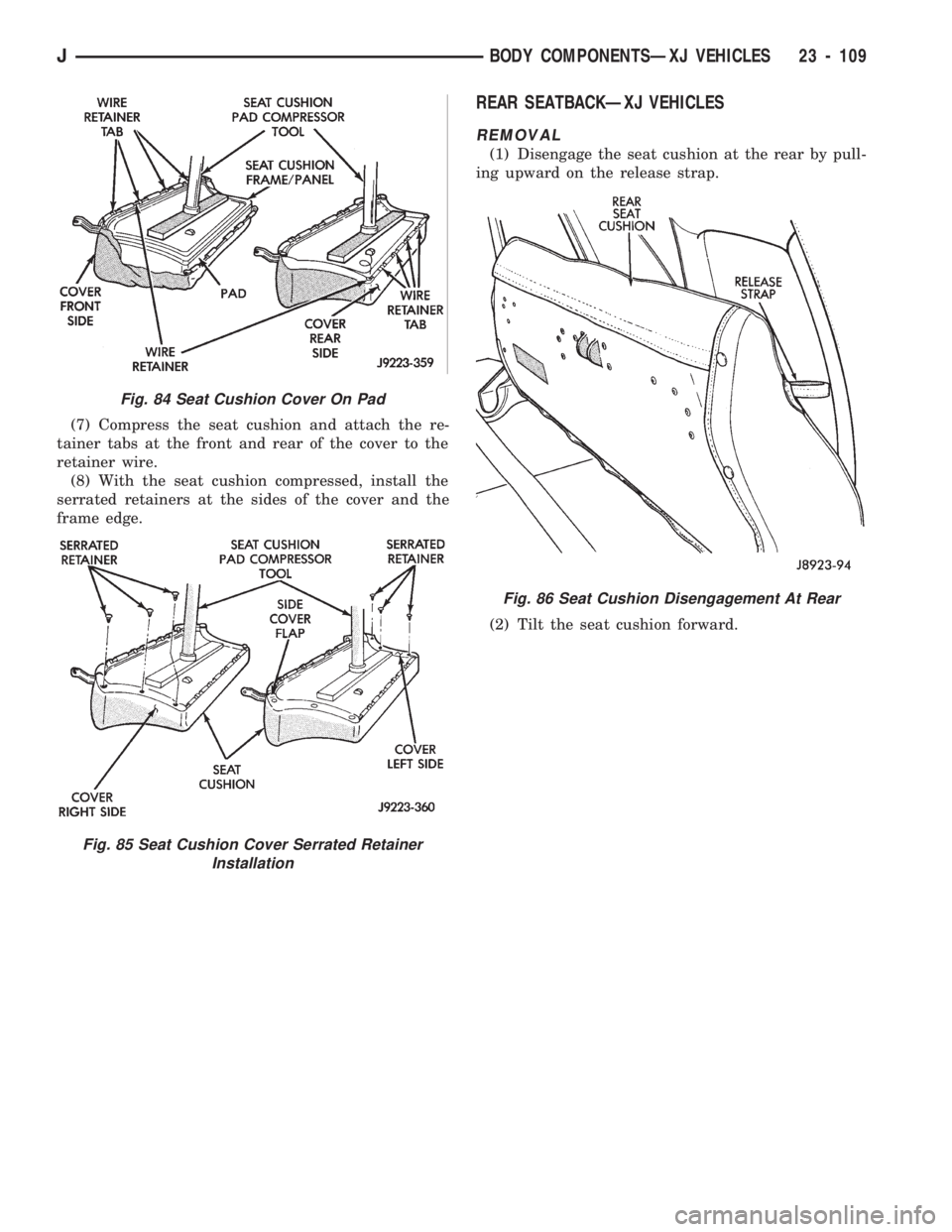
(7) Compress the seat cushion and attach the re-
tainer tabs at the front and rear of the cover to the
retainer wire.
(8) With the seat cushion compressed, install the
serrated retainers at the sides of the cover and the
frame edge.
REAR SEATBACKÐXJ VEHICLES
REMOVAL
(1) Disengage the seat cushion at the rear by pull-
ing upward on the release strap.
(2) Tilt the seat cushion forward.
Fig. 84 Seat Cushion Cover On Pad
Fig. 85 Seat Cushion Cover Serrated Retainer
Installation
Fig. 86 Seat Cushion Disengagement At Rear
JBODY COMPONENTSÐXJ VEHICLES 23 - 109
Page 1565 of 1784
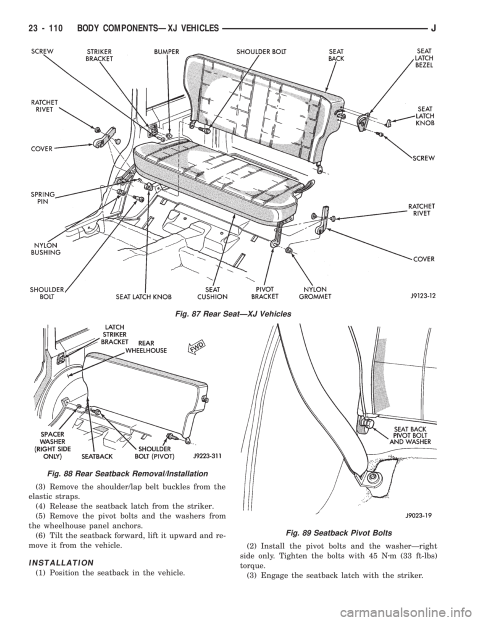
(3) Remove the shoulder/lap belt buckles from the
elastic straps.
(4) Release the seatback latch from the striker.
(5) Remove the pivot bolts and the washers from
the wheelhouse panel anchors.
(6) Tilt the seatback forward, lift it upward and re-
move it from the vehicle.
INSTALLATION
(1) Position the seatback in the vehicle.(2) Install the pivot bolts and the washerÐright
side only. Tighten the bolts with 45 Nzm (33 ft-lbs)
torque.
(3) Engage the seatback latch with the striker.
Fig. 87 Rear SeatÐXJ Vehicles
Fig. 88 Rear Seatback Removal/Installation
Fig. 89 Seatback Pivot Bolts
23 - 110 BODY COMPONENTSÐXJ VEHICLESJ
Page 1566 of 1784
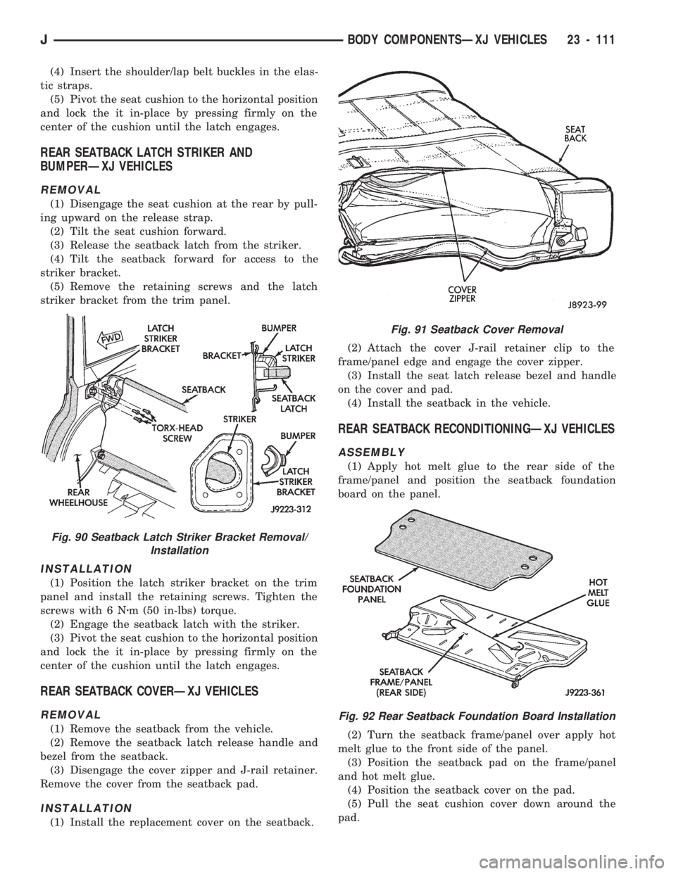
(4) Insert the shoulder/lap belt buckles in the elas-
tic straps.
(5) Pivot the seat cushion to the horizontal position
and lock the it in-place by pressing firmly on the
center of the cushion until the latch engages.
REAR SEATBACK LATCH STRIKER AND
BUMPERÐXJ VEHICLES
REMOVAL
(1) Disengage the seat cushion at the rear by pull-
ing upward on the release strap.
(2) Tilt the seat cushion forward.
(3) Release the seatback latch from the striker.
(4) Tilt the seatback forward for access to the
striker bracket.
(5) Remove the retaining screws and the latch
striker bracket from the trim panel.
INSTALLATION
(1) Position the latch striker bracket on the trim
panel and install the retaining screws. Tighten the
screws with 6 Nzm (50 in-lbs) torque.
(2) Engage the seatback latch with the striker.
(3) Pivot the seat cushion to the horizontal position
and lock the it in-place by pressing firmly on the
center of the cushion until the latch engages.
REAR SEATBACK COVERÐXJ VEHICLES
REMOVAL
(1) Remove the seatback from the vehicle.
(2) Remove the seatback latch release handle and
bezel from the seatback.
(3) Disengage the cover zipper and J-rail retainer.
Remove the cover from the seatback pad.
INSTALLATION
(1) Install the replacement cover on the seatback.(2) Attach the cover J-rail retainer clip to the
frame/panel edge and engage the cover zipper.
(3) Install the seat latch release bezel and handle
on the cover and pad.
(4) Install the seatback in the vehicle.
REAR SEATBACK RECONDITIONINGÐXJ VEHICLES
ASSEMBLY
(1) Apply hot melt glue to the rear side of the
frame/panel and position the seatback foundation
board on the panel.
(2) Turn the seatback frame/panel over apply hot
melt glue to the front side of the panel.
(3) Position the seatback pad on the frame/panel
and hot melt glue.
(4) Position the seatback cover on the pad.
(5) Pull the seat cushion cover down around the
pad.
Fig. 90 Seatback Latch Striker Bracket Removal/
Installation
Fig. 91 Seatback Cover Removal
Fig. 92 Rear Seatback Foundation Board Installation
JBODY COMPONENTSÐXJ VEHICLES 23 - 111
Page 1567 of 1784
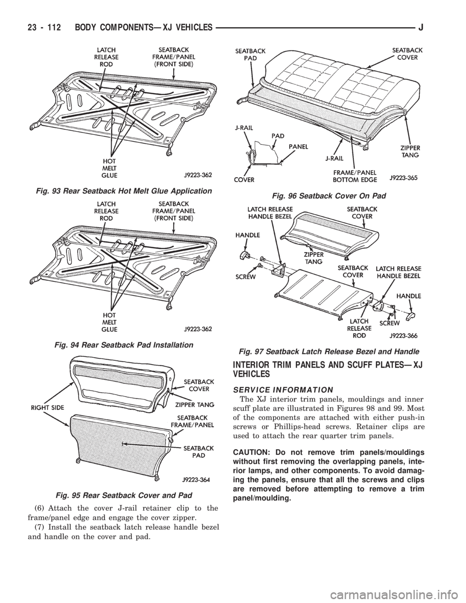
(6) Attach the cover J-rail retainer clip to the
frame/panel edge and engage the cover zipper.
(7) Install the seatback latch release handle bezel
and handle on the cover and pad.
INTERIOR TRIM PANELS AND SCUFF PLATESÐXJ
VEHICLES
SERVICE INFORMATION
The XJ interior trim panels, mouldings and inner
scuff plate are illustrated in Figures 98 and 99. Most
of the components are attached with either push-in
screws or Phillips-head screws. Retainer clips are
used to attach the rear quarter trim panels.
CAUTION: Do not remove trim panels/mouldings
without first removing the overlapping panels, inte-
rior lamps, and other components. To avoid damag-
ing the panels, ensure that all the screws and clips
are removed before attempting to remove a trim
panel/moulding.
Fig. 93 Rear Seatback Hot Melt Glue Application
Fig. 94 Rear Seatback Pad Installation
Fig. 95 Rear Seatback Cover and Pad
Fig. 96 Seatback Cover On Pad
Fig. 97 Seatback Latch Release Bezel and Handle
23 - 112 BODY COMPONENTSÐXJ VEHICLESJ
Page 1568 of 1784
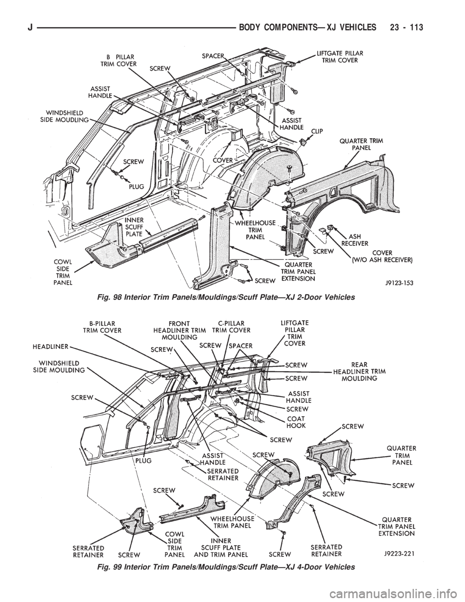
Fig. 98 Interior Trim Panels/Mouldings/Scuff PlateÐXJ 2-Door Vehicles
Fig. 99 Interior Trim Panels/Mouldings/Scuff PlateÐXJ 4-Door Vehicles
JBODY COMPONENTSÐXJ VEHICLES 23 - 113
Page 1569 of 1784
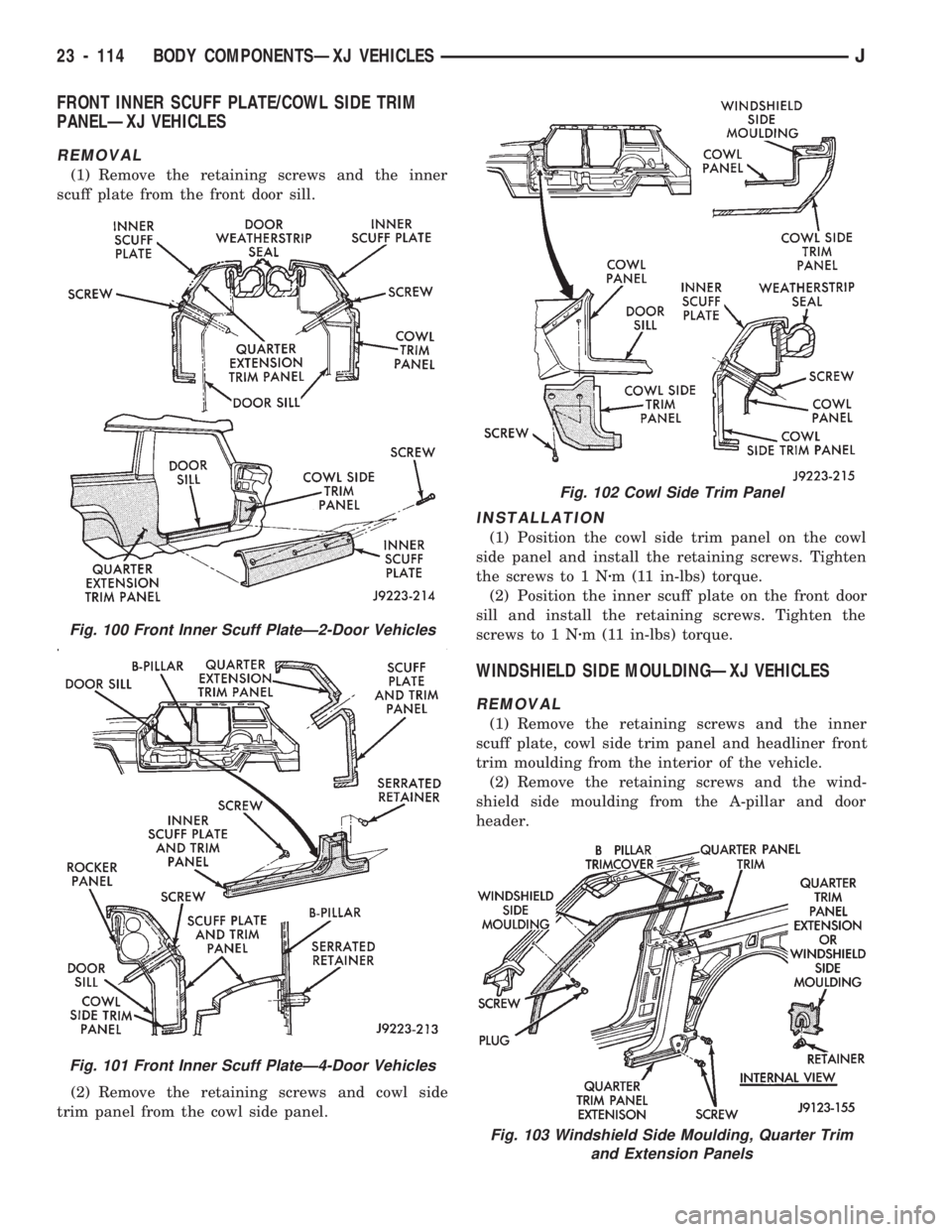
FRONT INNER SCUFF PLATE/COWL SIDE TRIM
PANELÐXJ VEHICLES
REMOVAL
(1) Remove the retaining screws and the inner
scuff plate from the front door sill.
(2) Remove the retaining screws and cowl side
trim panel from the cowl side panel.
INSTALLATION
(1) Position the cowl side trim panel on the cowl
side panel and install the retaining screws. Tighten
the screws to 1 Nzm (11 in-lbs) torque.
(2) Position the inner scuff plate on the front door
sill and install the retaining screws. Tighten the
screws to 1 Nzm (11 in-lbs) torque.
WINDSHIELD SIDE MOULDINGÐXJ VEHICLES
REMOVAL
(1) Remove the retaining screws and the inner
scuff plate, cowl side trim panel and headliner front
trim moulding from the interior of the vehicle.
(2) Remove the retaining screws and the wind-
shield side moulding from the A-pillar and door
header.
Fig. 100 Front Inner Scuff PlateÐ2-Door Vehicles
Fig. 101 Front Inner Scuff PlateÐ4-Door Vehicles
Fig. 102 Cowl Side Trim Panel
Fig. 103 Windshield Side Moulding, Quarter Trim
and Extension Panels
23 - 114 BODY COMPONENTSÐXJ VEHICLESJ
Page 1570 of 1784
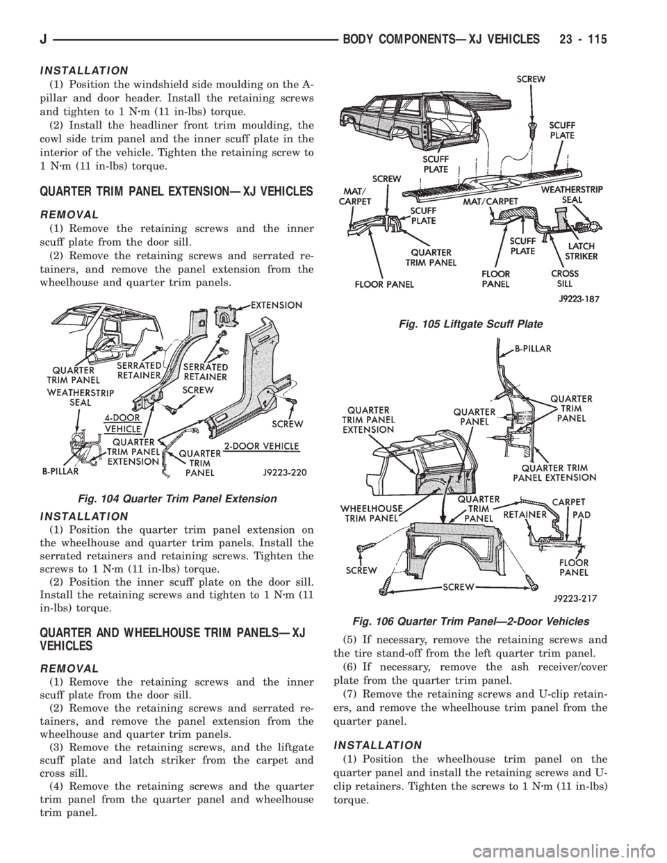
INSTALLATION
(1) Position the windshield side moulding on the A-
pillar and door header. Install the retaining screws
and tighten to 1 Nzm (11 in-lbs) torque.
(2) Install the headliner front trim moulding, the
cowl side trim panel and the inner scuff plate in the
interior of the vehicle. Tighten the retaining screw to
1Nzm (11 in-lbs) torque.
QUARTER TRIM PANEL EXTENSIONÐXJ VEHICLES
REMOVAL
(1) Remove the retaining screws and the inner
scuff plate from the door sill.
(2) Remove the retaining screws and serrated re-
tainers, and remove the panel extension from the
wheelhouse and quarter trim panels.
INSTALLATION
(1) Position the quarter trim panel extension on
the wheelhouse and quarter trim panels. Install the
serrated retainers and retaining screws. Tighten the
screws to 1 Nzm (11 in-lbs) torque.
(2) Position the inner scuff plate on the door sill.
Install the retaining screws and tighten to 1 Nzm(11
in-lbs) torque.
QUARTER AND WHEELHOUSE TRIM PANELSÐXJ
VEHICLES
REMOVAL
(1) Remove the retaining screws and the inner
scuff plate from the door sill.
(2) Remove the retaining screws and serrated re-
tainers, and remove the panel extension from the
wheelhouse and quarter trim panels.
(3) Remove the retaining screws, and the liftgate
scuff plate and latch striker from the carpet and
cross sill.
(4) Remove the retaining screws and the quarter
trim panel from the quarter panel and wheelhouse
trim panel.(5) If necessary, remove the retaining screws and
the tire stand-off from the left quarter trim panel.
(6) If necessary, remove the ash receiver/cover
plate from the quarter trim panel.
(7) Remove the retaining screws and U-clip retain-
ers, and remove the wheelhouse trim panel from the
quarter panel.
INSTALLATION
(1) Position the wheelhouse trim panel on the
quarter panel and install the retaining screws and U-
clip retainers. Tighten the screws to 1 Nzm (11 in-lbs)
torque.
Fig. 105 Liftgate Scuff Plate
Fig. 106 Quarter Trim PanelÐ2-Door Vehicles
Fig. 104 Quarter Trim Panel Extension
JBODY COMPONENTSÐXJ VEHICLES 23 - 115