JEEP CHEROKEE 1994 Service Repair Manual
Manufacturer: JEEP, Model Year: 1994, Model line: CHEROKEE, Model: JEEP CHEROKEE 1994Pages: 1784, PDF Size: 77.09 MB
Page 1551 of 1784
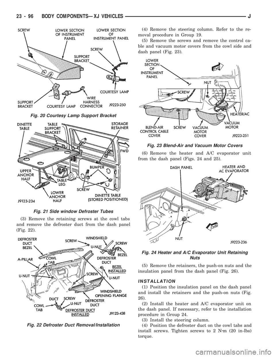
(3) Remove the retaining screws at the cowl tabs
and remove the defroster duct from the dash panel
(Fig. 22).(4) Remove the steering column. Refer to the re-
moval procedure in Group 19.
(5) Remove the screws and remove the control ca-
ble and vacuum motor covers from the cowl side and
dash panel (Fig. 23).
(6) Remove the heater and A/C evaporator unit
from the dash panel (Figs. 24 and 25).
(5) Remove the retainers, the push-on nuts and the
insulation panel from the dash panel (Fig. 26).
INSTALLATION
(1) Position the insulation panel on the dash panel
and install the retainers and the push-on nuts (Fig.
26).
(2) Install the heater and A/C evaporator unit on
the dash panel. If necessary, refer to the installation
procedure in Group 24.
(3) Install the steering column.
(4) Position the defroster duct on the cowl tabs and
install screws. Tighten screws to 2 Nzm (20 in-lbs)
torque.
Fig. 20 Courtesy Lamp Support Bracket
Fig. 21 Side window Defroster Tubes
Fig. 22 Defroster Duct Removal/Installation
Fig. 23 Blend-Air and Vacuum Motor Covers
Fig. 24 Heater and A/C Evaporator Unit Retaining
Nuts
23 - 96 BODY COMPONENTSÐXJ VEHICLESJ
Page 1552 of 1784
(5) Install the defroster tubes on the ducts.
(6) Install the instrument panel on the dash panel.
If necessary, refer to the installation procedure.
FRONT BUCKET SEATS
REMOVAL
Bucket seat platforms are attached to the floor
panel with studs and nuts. The trim covers are at-
tached to the platform with either push-on fasteners
(manual seats) or screws (power seats).
(1) Remove the seat platform trim cover push-on
fasteners/screws and remove the trim covers from the
seat platform.
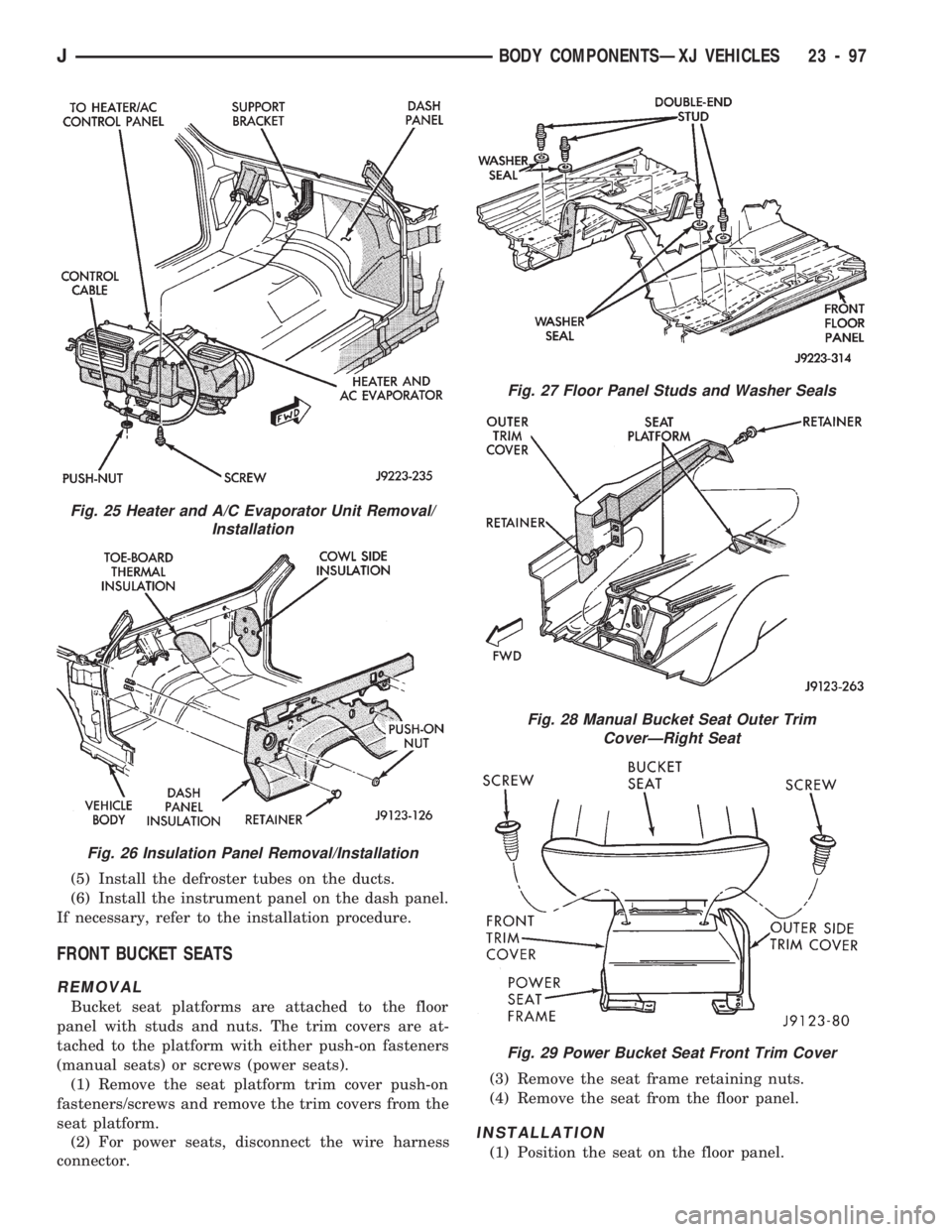
(2) For power seats, disconnect the wire harness
connector.(3) Remove the seat frame retaining nuts.
(4) Remove the seat from the floor panel.
INSTALLATION
(1) Position the seat on the floor panel.
Fig. 25 Heater and A/C Evaporator Unit Removal/
Installation
Fig. 26 Insulation Panel Removal/Installation
Fig. 27 Floor Panel Studs and Washer Seals
Fig. 28 Manual Bucket Seat Outer Trim
CoverÐRight Seat
Fig. 29 Power Bucket Seat Front Trim Cover
JBODY COMPONENTSÐXJ VEHICLES 23 - 97
Page 1553 of 1784
(2) Install and tighten the seat retaining nuts with
25 Nzm (18 ft-lbs) torque.
(3) For power seats, connect the wire harness con-
nector.
(4) Install the seat platform trim covers.
BUCKET SEAT CUSHION AND COVER
REMOVAL
(1) Remove the seat from the vehicle. If necessary,
refer to the removal procedure.
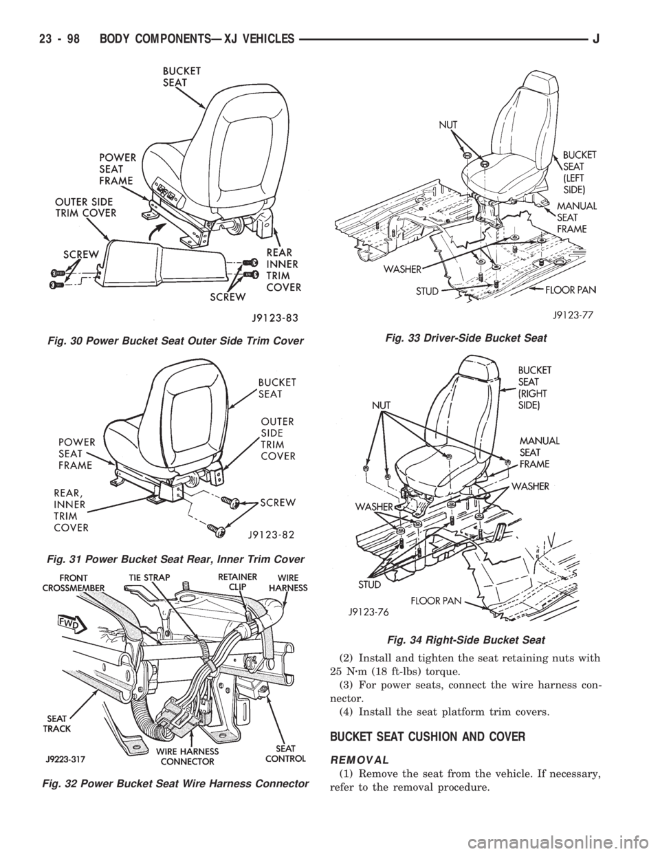
Fig. 30 Power Bucket Seat Outer Side Trim Cover
Fig. 31 Power Bucket Seat Rear, Inner Trim Cover
Fig. 32 Power Bucket Seat Wire Harness Connector
Fig. 33 Driver-Side Bucket Seat
Fig. 34 Right-Side Bucket Seat
23 - 98 BODY COMPONENTSÐXJ VEHICLESJ
Page 1554 of 1784
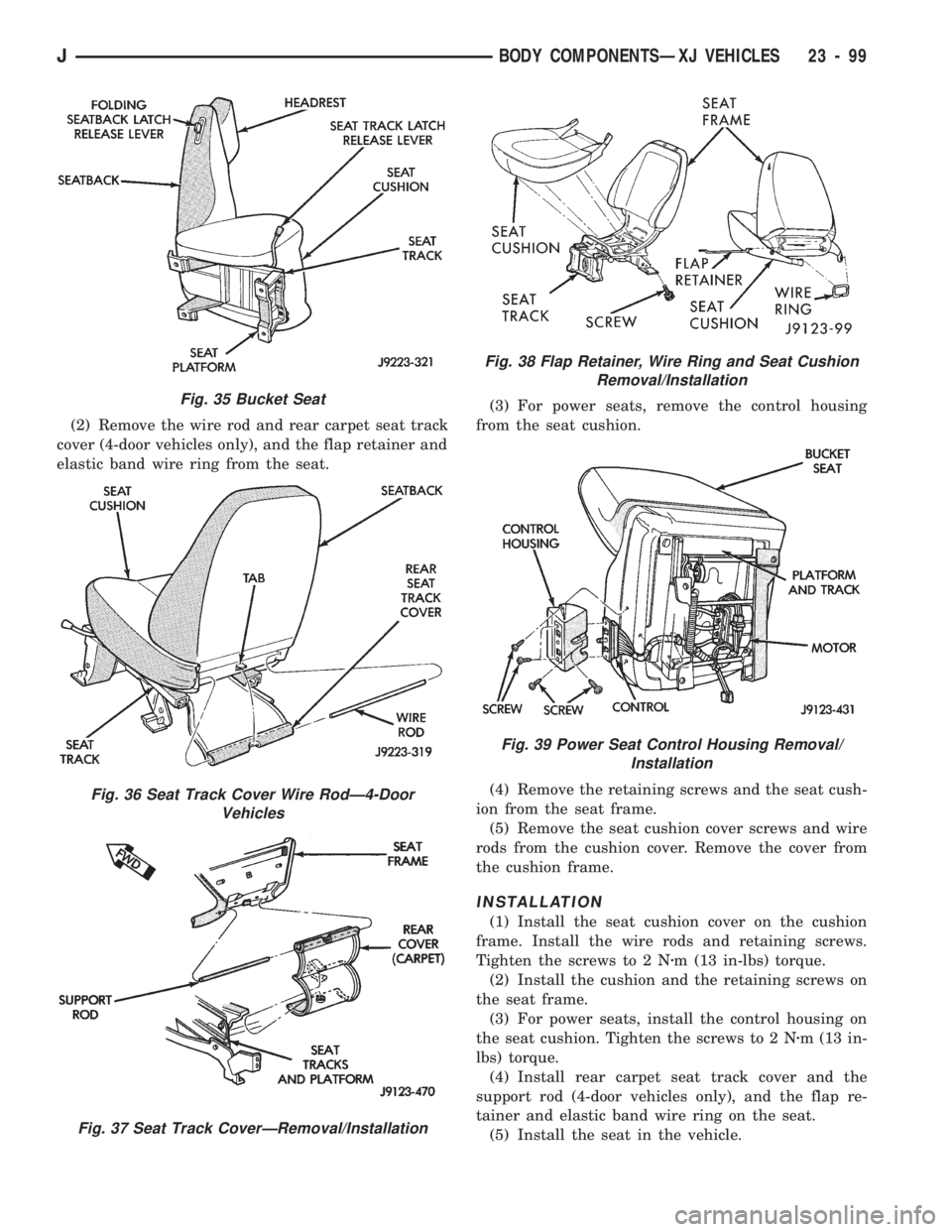
(2) Remove the wire rod and rear carpet seat track
cover (4-door vehicles only), and the flap retainer and
elastic band wire ring from the seat.(3) For power seats, remove the control housing
from the seat cushion.
(4) Remove the retaining screws and the seat cush-
ion from the seat frame.
(5) Remove the seat cushion cover screws and wire
rods from the cushion cover. Remove the cover from
the cushion frame.
INSTALLATION
(1) Install the seat cushion cover on the cushion
frame. Install the wire rods and retaining screws.
Tighten the screws to 2 Nzm (13 in-lbs) torque.
(2) Install the cushion and the retaining screws on
the seat frame.
(3) For power seats, install the control housing on
the seat cushion. Tighten the screws to 2 Nzm (13 in-
lbs) torque.
(4) Install rear carpet seat track cover and the
support rod (4-door vehicles only), and the flap re-
tainer and elastic band wire ring on the seat.
(5) Install the seat in the vehicle.
Fig. 35 Bucket Seat
Fig. 36 Seat Track Cover Wire RodÐ4-Door
Vehicles
Fig. 37 Seat Track CoverÐRemoval/Installation
Fig. 38 Flap Retainer, Wire Ring and Seat Cushion
Removal/Installation
Fig. 39 Power Seat Control Housing Removal/
Installation
JBODY COMPONENTSÐXJ VEHICLES 23 - 99
Page 1555 of 1784
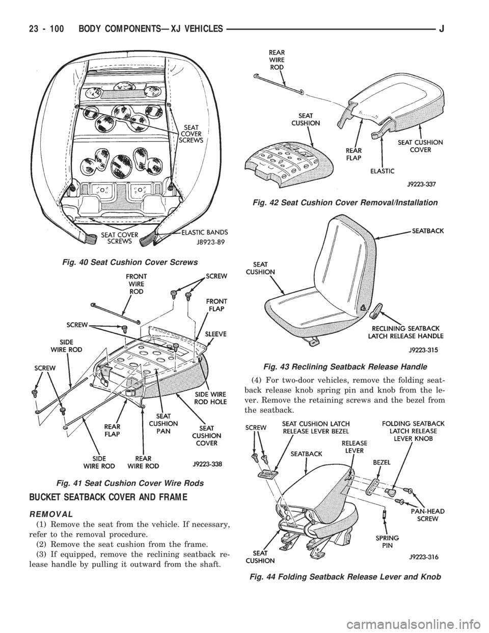
BUCKET SEATBACK COVER AND FRAME
REMOVAL
(1) Remove the seat from the vehicle. If necessary,
refer to the removal procedure.
(2) Remove the seat cushion from the frame.
(3) If equipped, remove the reclining seatback re-
lease handle by pulling it outward from the shaft.(4) For two-door vehicles, remove the folding seat-
back release knob spring pin and knob from the le-
ver. Remove the retaining screws and the bezel from
the seatback.
Fig. 40 Seat Cushion Cover Screws
Fig. 41 Seat Cushion Cover Wire Rods
Fig. 42 Seat Cushion Cover Removal/Installation
Fig. 43 Reclining Seatback Release Handle
Fig. 44 Folding Seatback Release Lever and Knob
23 - 100 BODY COMPONENTSÐXJ VEHICLESJ
Page 1556 of 1784
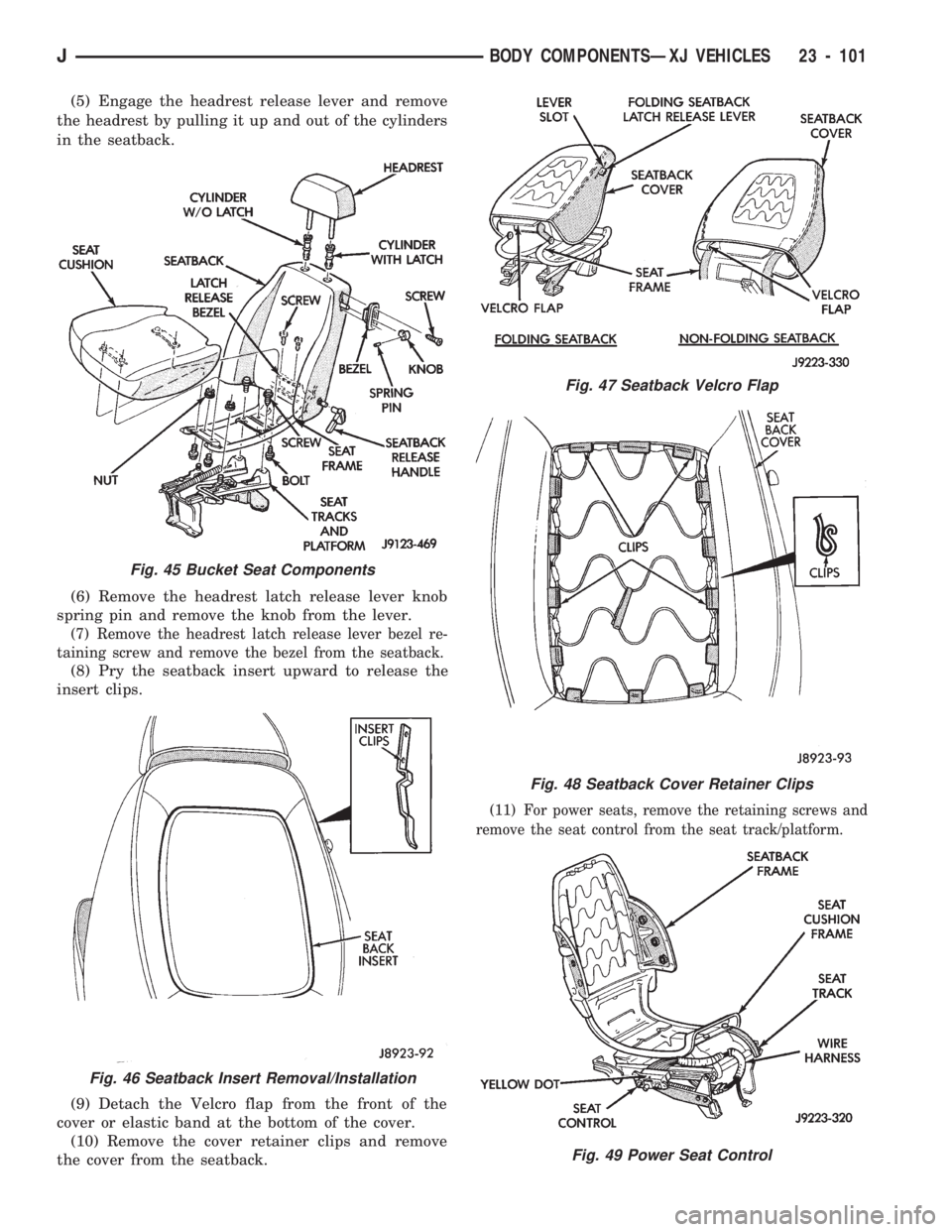
(5) Engage the headrest release lever and remove
the headrest by pulling it up and out of the cylinders
in the seatback.
(6) Remove the headrest latch release lever knob
spring pin and remove the knob from the lever.
(7) Remove the headrest latch release lever bezel re-
taining screw and remove the bezel from the seatback.
(8) Pry the seatback insert upward to release the
insert clips.
(9) Detach the Velcro flap from the front of the
cover or elastic band at the bottom of the cover.
(10) Remove the cover retainer clips and remove
the cover from the seatback.
(11) For power seats, remove the retaining screws and
remove the seat control from the seat track/platform.
Fig. 45 Bucket Seat Components
Fig. 46 Seatback Insert Removal/Installation
Fig. 47 Seatback Velcro Flap
Fig. 48 Seatback Cover Retainer Clips
Fig. 49 Power Seat Control
JBODY COMPONENTSÐXJ VEHICLES 23 - 101
Page 1557 of 1784
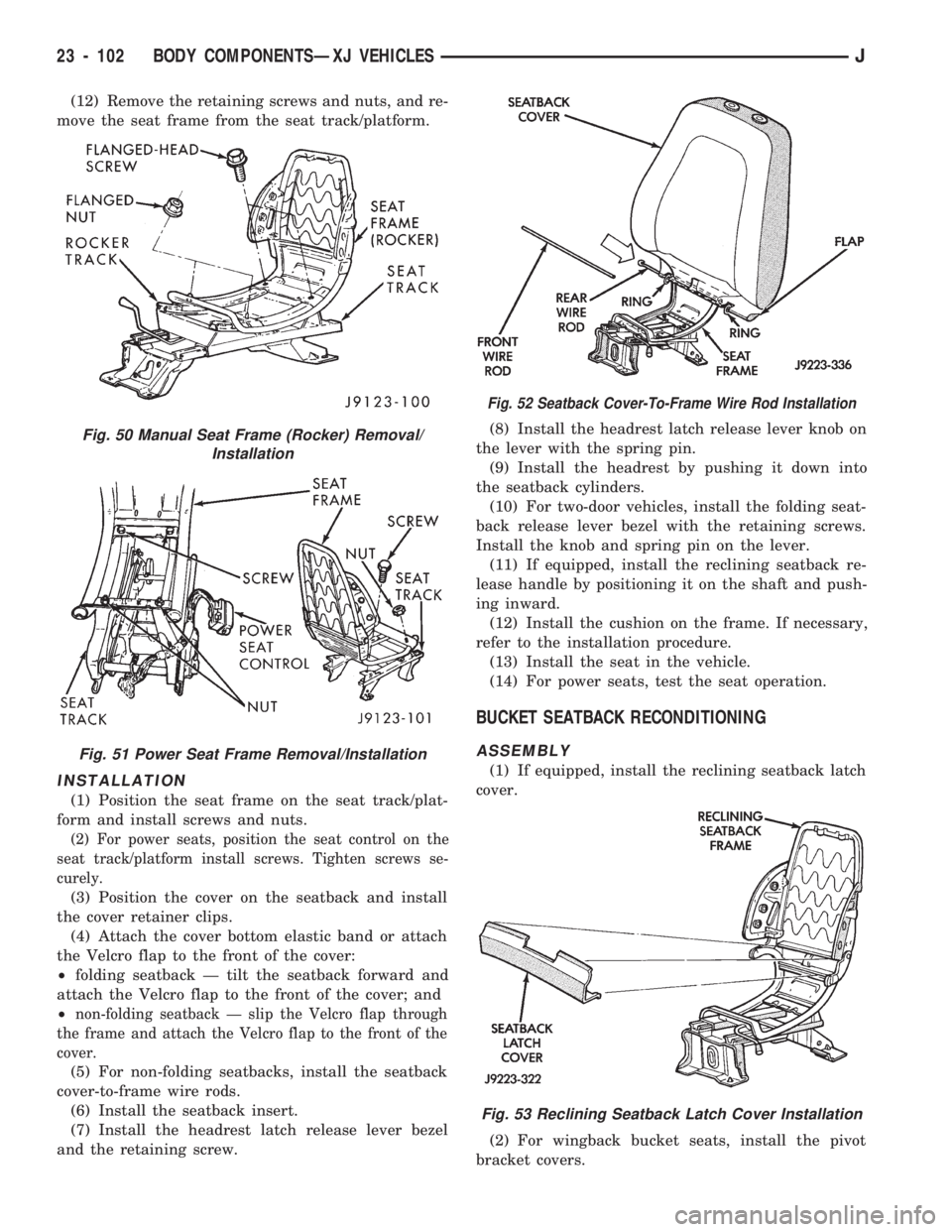
(12) Remove the retaining screws and nuts, and re-
move the seat frame from the seat track/platform.
INSTALLATION
(1) Position the seat frame on the seat track/plat-
form and install screws and nuts.
(2) For power seats, position the seat control on the
seat track/platform install screws. Tighten screws se-
curely.
(3) Position the cover on the seatback and install
the cover retainer clips.
(4) Attach the cover bottom elastic band or attach
the Velcro flap to the front of the cover:
²folding seatback Ð tilt the seatback forward and
attach the Velcro flap to the front of the cover; and
²
non-folding seatback Ð slip the Velcro flap through
the frame and attach the Velcro flap to the front of the
cover.
(5) For non-folding seatbacks, install the seatback
cover-to-frame wire rods.
(6) Install the seatback insert.
(7) Install the headrest latch release lever bezel
and the retaining screw.(8) Install the headrest latch release lever knob on
the lever with the spring pin.
(9) Install the headrest by pushing it down into
the seatback cylinders.
(10) For two-door vehicles, install the folding seat-
back release lever bezel with the retaining screws.
Install the knob and spring pin on the lever.
(11) If equipped, install the reclining seatback re-
lease handle by positioning it on the shaft and push-
ing inward.
(12) Install the cushion on the frame. If necessary,
refer to the installation procedure.
(13) Install the seat in the vehicle.
(14) For power seats, test the seat operation.
BUCKET SEATBACK RECONDITIONING
ASSEMBLY
(1) If equipped, install the reclining seatback latch
cover.
(2) For wingback bucket seats, install the pivot
bracket covers.
Fig. 50 Manual Seat Frame (Rocker) Removal/
Installation
Fig. 51 Power Seat Frame Removal/Installation
Fig. 52 Seatback Cover-To-Frame Wire Rod Installation
Fig. 53 Reclining Seatback Latch Cover Installation
23 - 102 BODY COMPONENTSÐXJ VEHICLESJ
Page 1558 of 1784
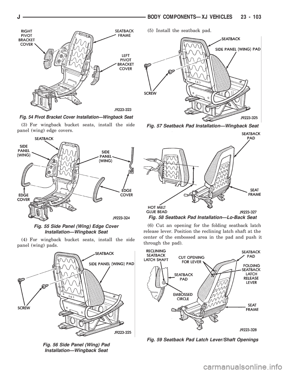
(3) For wingback bucket seats, install the side
panel (wing) edge covers.
(4) For wingback bucket seats, install the side
panel (wing) pads.(5) Install the seatback pad.
(6) Cut an opening for the folding seatback latch
release lever. Position the reclining latch shaft at the
center of the embossed area in the pad and push it
through the pad).
Fig. 56 Side Panel (Wing) Pad
InstallationÐWingback Seat
Fig. 54 Pivot Bracket Cover InstallationÐWingback Seat
Fig. 55 Side Panel (Wing) Edge Cover
InstallationÐWingback Seat
Fig. 57 Seatback Pad InstallationÐWingback Seat
Fig. 58 Seatback Pad InstallationÐLo-Back Seat
Fig. 59 Seatback Pad Latch Lever/Shaft Openings
JBODY COMPONENTSÐXJ VEHICLES 23 - 103
Page 1559 of 1784
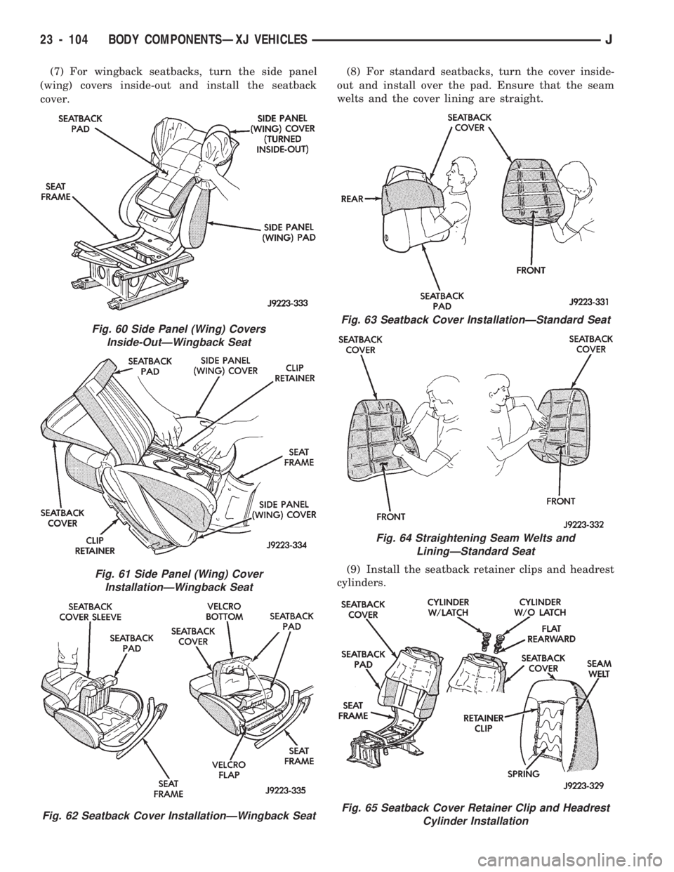
(7) For wingback seatbacks, turn the side panel
(wing) covers inside-out and install the seatback
cover.(8) For standard seatbacks, turn the cover inside-
out and install over the pad. Ensure that the seam
welts and the cover lining are straight.
(9) Install the seatback retainer clips and headrest
cylinders.
Fig. 60 Side Panel (Wing) Covers
Inside-OutÐWingback Seat
Fig. 61 Side Panel (Wing) Cover
InstallationÐWingback Seat
Fig. 62 Seatback Cover InstallationÐWingback Seat
Fig. 63 Seatback Cover InstallationÐStandard Seat
Fig. 64 Straightening Seam Welts and
LiningÐStandard Seat
Fig. 65 Seatback Cover Retainer Clip and Headrest
Cylinder Installation
23 - 104 BODY COMPONENTSÐXJ VEHICLESJ
Page 1560 of 1784
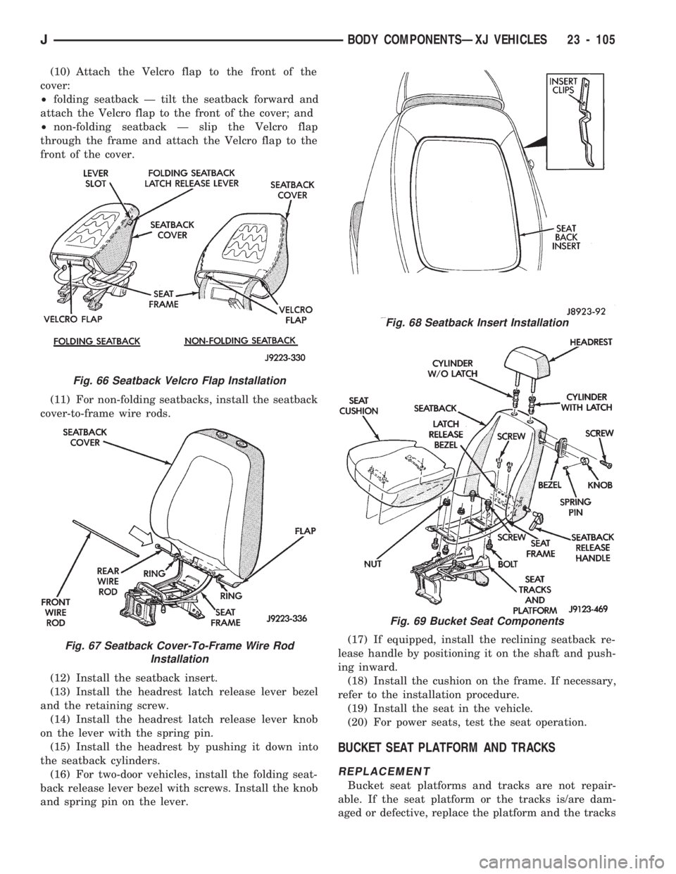
(10) Attach the Velcro flap to the front of the
cover:
²folding seatback Ð tilt the seatback forward and
attach the Velcro flap to the front of the cover; and
²non-folding seatback Ð slip the Velcro flap
through the frame and attach the Velcro flap to the
front of the cover.
(11) For non-folding seatbacks, install the seatback
cover-to-frame wire rods.
(12) Install the seatback insert.
(13) Install the headrest latch release lever bezel
and the retaining screw.
(14) Install the headrest latch release lever knob
on the lever with the spring pin.
(15) Install the headrest by pushing it down into
the seatback cylinders.
(16) For two-door vehicles, install the folding seat-
back release lever bezel with screws. Install the knob
and spring pin on the lever.(17) If equipped, install the reclining seatback re-
lease handle by positioning it on the shaft and push-
ing inward.
(18) Install the cushion on the frame. If necessary,
refer to the installation procedure.
(19) Install the seat in the vehicle.
(20) For power seats, test the seat operation.
BUCKET SEAT PLATFORM AND TRACKS
REPLACEMENT
Bucket seat platforms and tracks are not repair-
able. If the seat platform or the tracks is/are dam-
aged or defective, replace the platform and the tracks
Fig. 66 Seatback Velcro Flap Installation
Fig. 67 Seatback Cover-To-Frame Wire Rod
Installation
Fig. 68 Seatback Insert Installation
Fig. 69 Bucket Seat Components
JBODY COMPONENTSÐXJ VEHICLES 23 - 105