JEEP CHEROKEE 1994 Service Repair Manual
Manufacturer: JEEP, Model Year: 1994, Model line: CHEROKEE, Model: JEEP CHEROKEE 1994Pages: 1784, PDF Size: 77.09 MB
Page 171 of 1784
DISC BRAKES
INDEX
page page
Caliper Assembly........................ 29
Caliper Cleaning and Inspection............. 28
Caliper Disassembly...................... 27
Caliper Installation........................ 30
Caliper Operation and Wear Compensation..... 24
Caliper Removal......................... 27
Disc Brake Rotor Refinishing................ 32
Disc Brake Rotor Runout................... 31Disc Brake Rotor Thickness................ 31
Disc Brake Rotor Thickness Variation......... 31
Disc Brakeshoe Installation................. 26
Disc Brakeshoe Removal.................. 25
General Information....................... 24
Rotor Installation......................... 30
Rotor Removal.......................... 30
Wheel Nut Tightening..................... 32
GENERAL INFORMATION
1994 Jeep XJ/YJ models are equipped with single
piston, floating-type disc brake calipers. Ventilated,
cast rotors are used for all applications.
The disc brake calipers are supported in mounting
arms that are an integral part of the steering
knuckle. The calipers slide on mounting bolts that
also attach the calipers to the steering knuckle.
CALIPER OPERATION AND WEAR COMPENSATION
Caliper Operation
The significant feature of single piston caliper op-
eration is that the calipers are free to slide laterally
on the mounting bolts. It is the freedom of lateral
movement that allows continous compensation for
lining wear.
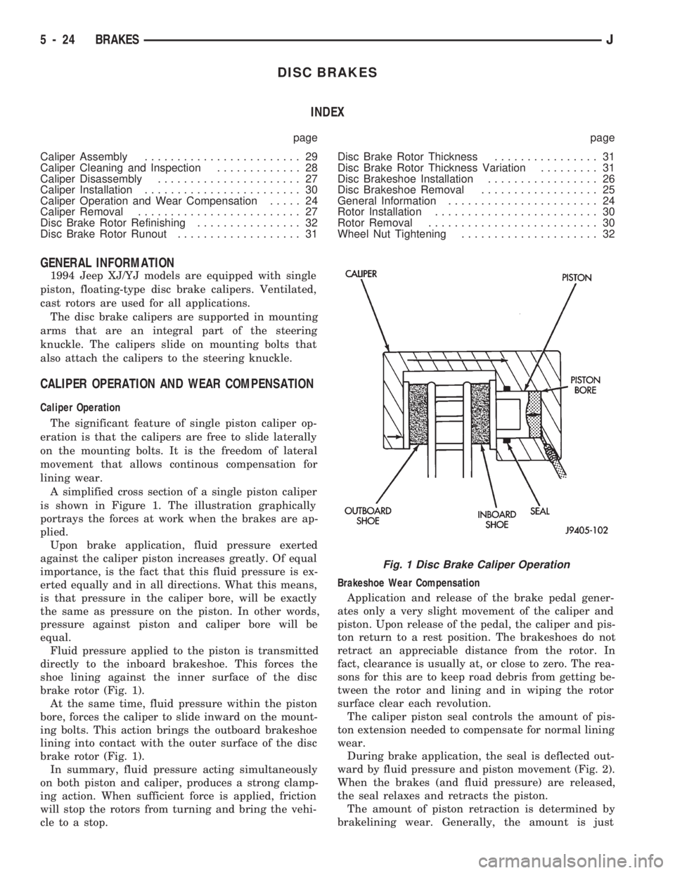
A simplified cross section of a single piston caliper
is shown in Figure 1. The illustration graphically
portrays the forces at work when the brakes are ap-
plied.
Upon brake application, fluid pressure exerted
against the caliper piston increases greatly. Of equal
importance, is the fact that this fluid pressure is ex-
erted equally and in all directions. What this means,
is that pressure in the caliper bore, will be exactly
the same as pressure on the piston. In other words,
pressure against piston and caliper bore will be
equal.
Fluid pressure applied to the piston is transmitted
directly to the inboard brakeshoe. This forces the
shoe lining against the inner surface of the disc
brake rotor (Fig. 1).
At the same time, fluid pressure within the piston
bore, forces the caliper to slide inward on the mount-
ing bolts. This action brings the outboard brakeshoe
lining into contact with the outer surface of the disc
brake rotor (Fig. 1).
In summary, fluid pressure acting simultaneously
on both piston and caliper, produces a strong clamp-
ing action. When sufficient force is applied, friction
will stop the rotors from turning and bring the vehi-
cle to a stop.Brakeshoe Wear Compensation
Application and release of the brake pedal gener-
ates only a very slight movement of the caliper and
piston. Upon release of the pedal, the caliper and pis-
ton return to a rest position. The brakeshoes do not
retract an appreciable distance from the rotor. In
fact, clearance is usually at, or close to zero. The rea-
sons for this are to keep road debris from getting be-
tween the rotor and lining and in wiping the rotor
surface clear each revolution.
The caliper piston seal controls the amount of pis-
ton extension needed to compensate for normal lining
wear.
During brake application, the seal is deflected out-
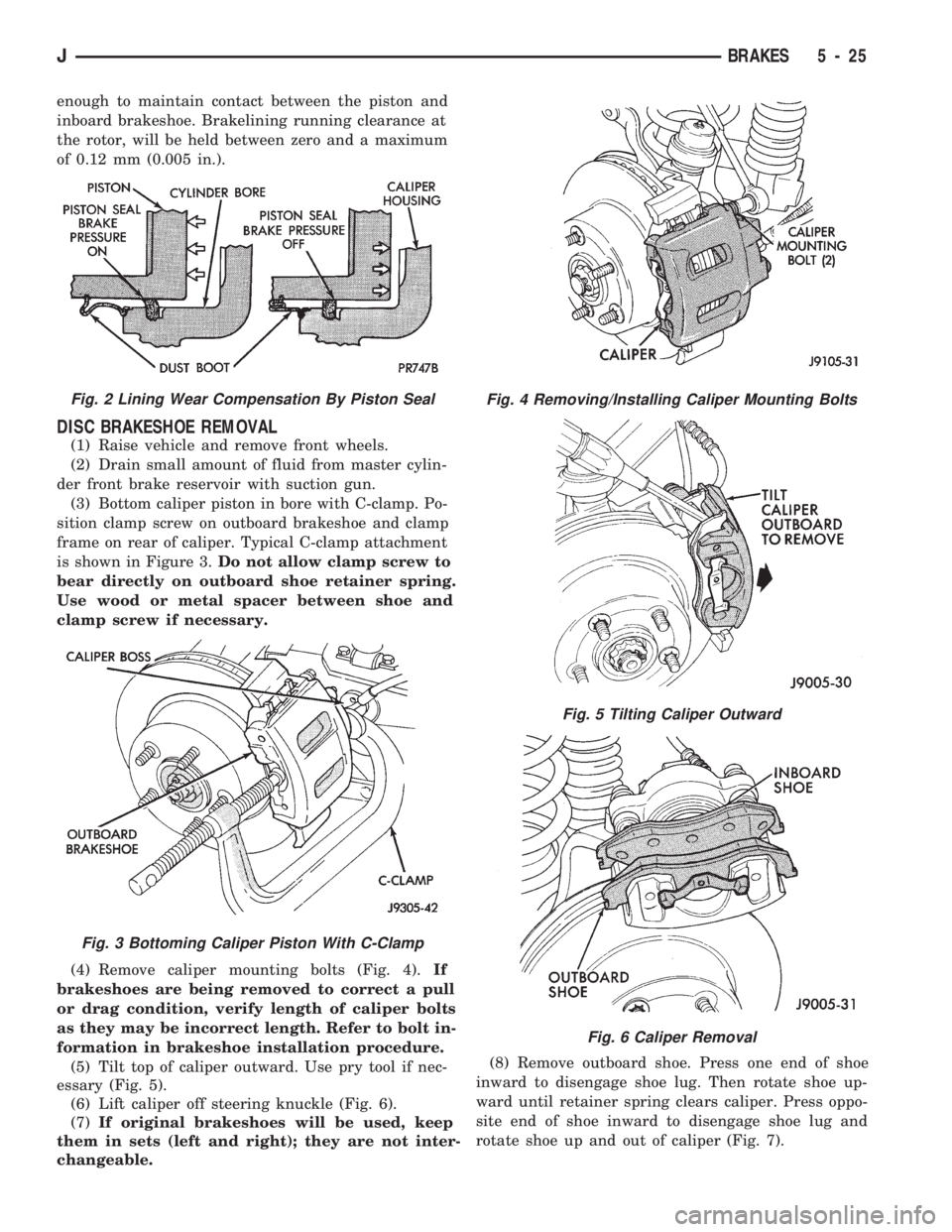
ward by fluid pressure and piston movement (Fig. 2).
When the brakes (and fluid pressure) are released,
the seal relaxes and retracts the piston.
The amount of piston retraction is determined by
brakelining wear. Generally, the amount is just
Fig. 1 Disc Brake Caliper Operation
5 - 24 BRAKESJ
Page 172 of 1784
enough to maintain contact between the piston and
inboard brakeshoe. Brakelining running clearance at
the rotor, will be held between zero and a maximum
of 0.12 mm (0.005 in.).
DISC BRAKESHOE REMOVAL
(1) Raise vehicle and remove front wheels.
(2) Drain small amount of fluid from master cylin-
der front brake reservoir with suction gun.
(3) Bottom caliper piston in bore with C-clamp. Po-
sition clamp screw on outboard brakeshoe and clamp
frame on rear of caliper. Typical C-clamp attachment
is shown in Figure 3.Do not allow clamp screw to
bear directly on outboard shoe retainer spring.
Use wood or metal spacer between shoe and
clamp screw if necessary.
(4) Remove caliper mounting bolts (Fig. 4).If
brakeshoes are being removed to correct a pull
or drag condition, verify length of caliper bolts
as they may be incorrect length. Refer to bolt in-
formation in brakeshoe installation procedure.
(5) Tilt top of caliper outward. Use pry tool if nec-
essary (Fig. 5).
(6) Lift caliper off steering knuckle (Fig. 6).
(7)If original brakeshoes will be used, keep
them in sets (left and right); they are not inter-
changeable.(8) Remove outboard shoe. Press one end of shoe
inward to disengage shoe lug. Then rotate shoe up-
ward until retainer spring clears caliper. Press oppo-
site end of shoe inward to disengage shoe lug and
rotate shoe up and out of caliper (Fig. 7).
Fig. 2 Lining Wear Compensation By Piston Seal
Fig. 3 Bottoming Caliper Piston With C-Clamp
Fig. 4 Removing/Installing Caliper Mounting Bolts
Fig. 5 Tilting Caliper Outward
Fig. 6 Caliper Removal
JBRAKES 5 - 25
Page 173 of 1784
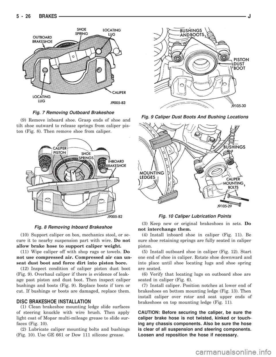
(9) Remove inboard shoe. Grasp ends of shoe and
tilt shoe outward to release springs from caliper pis-
ton (Fig. 8). Then remove shoe from caliper.
(10) Support caliper on box, mechanics stool, or se-
cure it to nearby suspension part with wire.Do not
allow brake hose to support caliper weight.
(11) Wipe caliper off with shop rags or towels.Do
not use compressed air. Compressed air can un-
seat dust boot and force dirt into piston bore.
(12) Inspect condition of caliper piston dust boot
(Fig. 9). Overhaul caliper if there is evidence of leak-
age past piston and dust boot. Then inspect caliper
bushings and boots (Fig. 9). Replace boots if torn or
cut. If bushings or boots are damaged, replace them.
DISC BRAKESHOE INSTALLATION
(1) Clean brakeshoe mounting ledge slide surfaces
of steering knuckle with wire brush. Then apply
light coat of Mopar multi-mileage grease to slide sur-
faces (Fig. 10).
(2) Lubricate caliper mounting bolts and bushings
(Fig. 10). Use GE 661 or Dow 111 silicone grease.(3) Keep new or original brakeshoes in sets.Do
not interchange them.
(4) Install inboard shoe in caliper (Fig. 11). Be
sure shoe retaining springs are fully seated in caliper
piston.
(5) Install outboard shoe in caliper (Fig. 12). Start
one end of shoe in caliper. Rotate shoe downward and
into place until shoe locating lugs and shoe spring
are seated.
(6) Verify that locating lugs on outboard shoe are
seated in caliper (Fig. 6).
(7) Install caliper. Position notches at lower end of
brakeshoes on bottom mounting ledge (Fig. 13). Then
install caliper over rotor and seat upper ends of
brakeshoes on top mounting ledge (Fig. 11).
CAUTION: Before securing the caliper, be sure the
caliper brake hose is not twisted, kinked or touch-
ing any chassis components. Also be sure the hose
is clear of all suspension and steering components.
Loosen and reposition the hose if necessary.
Fig. 7 Removing Outboard Brakeshoe
Fig. 8 Removing Inboard Brakeshoe
Fig. 9 Caliper Dust Boots And Bushing Locations
Fig. 10 Caliper Lubrication Points
5 - 26 BRAKESJ
Page 174 of 1784
(8) Install and tighten caliper mounting bolts to
10-20 Nzm (7-15 ft. lbs.) torque.
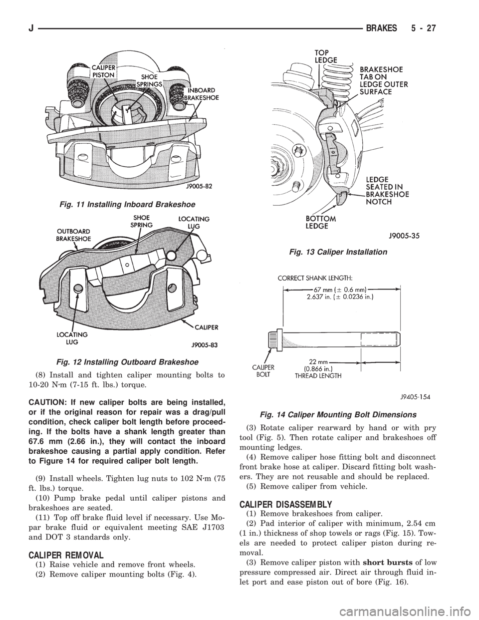
CAUTION: If new caliper bolts are being installed,
or if the original reason for repair was a drag/pull
condition, check caliper bolt length before proceed-
ing. If the bolts have a shank length greater than
67.6 mm (2.66 in.), they will contact the inboard
brakeshoe causing a partial apply condition. Refer
to Figure 14 for required caliper bolt length.
(9) Install wheels. Tighten lug nuts to 102 Nzm (75
ft. lbs.) torque.
(10) Pump brake pedal until caliper pistons and
brakeshoes are seated.
(11) Top off brake fluid level if necessary. Use Mo-
par brake fluid or equivalent meeting SAE J1703
and DOT 3 standards only.
CALIPER REMOVAL
(1) Raise vehicle and remove front wheels.
(2) Remove caliper mounting bolts (Fig. 4).(3) Rotate caliper rearward by hand or with pry
tool (Fig. 5). Then rotate caliper and brakeshoes off
mounting ledges.
(4) Remove caliper hose fitting bolt and disconnect
front brake hose at caliper. Discard fitting bolt wash-
ers. They are not reusable and should be replaced.
(5) Remove caliper from vehicle.
CALIPER DISASSEMBLY
(1) Remove brakeshoes from caliper.
(2) Pad interior of caliper with minimum, 2.54 cm
(1 in.) thickness of shop towels or rags (Fig. 15). Tow-
els are needed to protect caliper piston during re-
moval.
(3) Remove caliper piston withshort burstsof low
pressure compressed air. Direct air through fluid in-
let port and ease piston out of bore (Fig. 16).
Fig. 11 Installing Inboard Brakeshoe
Fig. 12 Installing Outboard Brakeshoe
Fig. 13 Caliper Installation
Fig. 14 Caliper Mounting Bolt Dimensions
JBRAKES 5 - 27
Page 175 of 1784
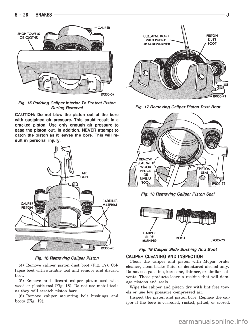
CAUTION: Do not blow the piston out of the bore
with sustained air pressure. This could result in a
cracked piston. Use only enough air pressure to
ease the piston out. In addition, NEVER attempt to
catch the piston as it leaves the bore. This will re-
sult in personal injury.
(4) Remove caliper piston dust boot (Fig. 17). Col-
lapse boot with suitable tool and remove and discard
boot.
(5) Remove and discard caliper piston seal with
wood or plastic tool (Fig. 18). Do not use metal tools
as they will scratch piston bore.
(6) Remove caliper mounting bolt bushings and
boots (Fig. 19).
CALIPER CLEANING AND INSPECTION
Clean the caliper and piston with Mopar brake
cleaner, clean brake fluid, or denatured alcohol only.
Do not use gasoline, kerosene, thinner, or similar sol-
vents. These products leave a residue that will dam-
age pistons and seals.
Wipe the caliper and piston dry with lint free tow-
els or use low pressure compressed air.
Inspect the piston and piston bore. Replace the cal-
iper if the bore is corroded, rusted, pitted, or scored.
Fig. 15 Padding Caliper Interior To Protect Piston
During Removal
Fig. 16 Removing Caliper Piston
Fig. 17 Removing Caliper Piston Dust Boot
Fig. 18 Removing Caliper Piston Seal
Fig. 19 Caliper Slide Bushing And Boot
5 - 28 BRAKESJ
Page 176 of 1784
Do not hone the caliper piston bore. Replace the cal-
iper if the bore exhibits any of the aforementioned
conditions.
Inspect the caliper piston. The piston is made from
a phenolic resin (plastic material) and should be
smooth and clean. Replace the piston if cracked,
chipped, or scored. Do not attempt to restore a
scored, or corroded piston surface by sanding or pol-
ishing. The piston must be replaced if damaged.
CAUTION: Never interchange phenolic resin and
steel caliper pistons. The seals, seal grooves, cali-
per bores and piston tolerances are different for
resin and steel pistons. Do not intermix these com-
ponents.
Inspect the caliper mounting bolt bushings and
boots. Replace the boots if cut or torn. Clean and lu-
bricate the bushings with GE 661 or Dow 111 sili-
cone grease if necessary.
Inspect condition of the caliper mounting bolts. Re-
place the bolts if corroded, rusted, or worn. Do not re-
use the bolts if unsure of their condition.
Length of the caliper mounting bolts is also ex-
tremely important.
Use the replacement bolts specified in the parts
catalog at all times. Do not use substitute bolts.
Bolts that are too long will partially apply the in-
board brakeshoe causing drag and pull. Refer to the
caliper and brakeshoe installation procedures for ser-
vice details and bolt dimensions.
CALIPER ASSEMBLY
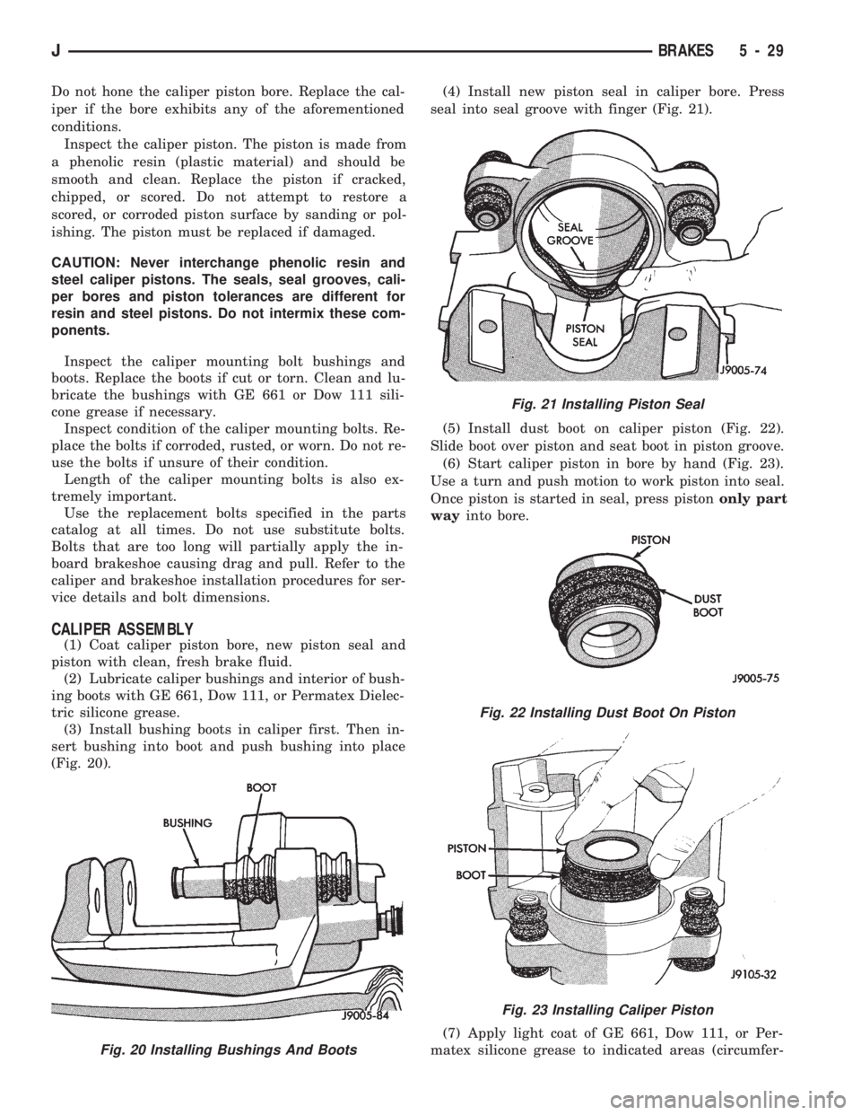
(1) Coat caliper piston bore, new piston seal and
piston with clean, fresh brake fluid.
(2) Lubricate caliper bushings and interior of bush-
ing boots with GE 661, Dow 111, or Permatex Dielec-
tric silicone grease.
(3) Install bushing boots in caliper first. Then in-
sert bushing into boot and push bushing into place
(Fig. 20).(4) Install new piston seal in caliper bore. Press
seal into seal groove with finger (Fig. 21).
(5) Install dust boot on caliper piston (Fig. 22).
Slide boot over piston and seat boot in piston groove.
(6) Start caliper piston in bore by hand (Fig. 23).
Use a turn and push motion to work piston into seal.
Once piston is started in seal, press pistononly part
wayinto bore.
(7) Apply light coat of GE 661, Dow 111, or Per-
matex silicone grease to indicated areas (circumfer-
Fig. 20 Installing Bushings And Boots
Fig. 21 Installing Piston Seal
Fig. 22 Installing Dust Boot On Piston
Fig. 23 Installing Caliper Piston
JBRAKES 5 - 29
Page 177 of 1784
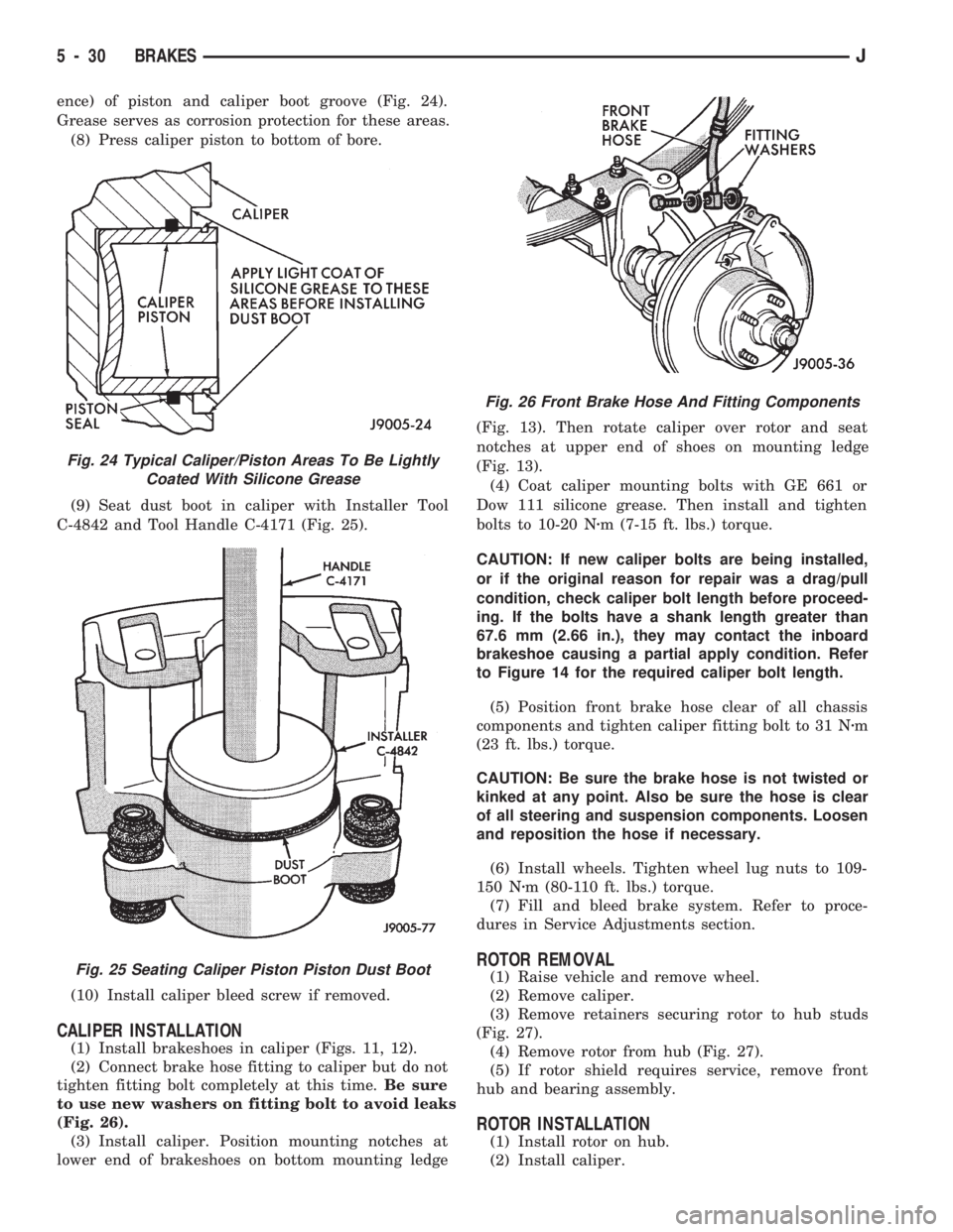
ence) of piston and caliper boot groove (Fig. 24).
Grease serves as corrosion protection for these areas.
(8) Press caliper piston to bottom of bore.
(9) Seat dust boot in caliper with Installer Tool
C-4842 and Tool Handle C-4171 (Fig. 25).
(10) Install caliper bleed screw if removed.
CALIPER INSTALLATION
(1) Install brakeshoes in caliper (Figs. 11, 12).
(2) Connect brake hose fitting to caliper but do not
tighten fitting bolt completely at this time.Be sure
to use new washers on fitting bolt to avoid leaks
(Fig. 26).
(3) Install caliper. Position mounting notches at
lower end of brakeshoes on bottom mounting ledge(Fig. 13). Then rotate caliper over rotor and seat
notches at upper end of shoes on mounting ledge
(Fig. 13).
(4) Coat caliper mounting bolts with GE 661 or
Dow 111 silicone grease. Then install and tighten
bolts to 10-20 Nzm (7-15 ft. lbs.) torque.
CAUTION: If new caliper bolts are being installed,
or if the original reason for repair was a drag/pull
condition, check caliper bolt length before proceed-
ing. If the bolts have a shank length greater than
67.6 mm (2.66 in.), they may contact the inboard
brakeshoe causing a partial apply condition. Refer
to Figure 14 for the required caliper bolt length.
(5) Position front brake hose clear of all chassis
components and tighten caliper fitting bolt to 31 Nzm
(23 ft. lbs.) torque.
CAUTION: Be sure the brake hose is not twisted or
kinked at any point. Also be sure the hose is clear
of all steering and suspension components. Loosen
and reposition the hose if necessary.
(6) Install wheels. Tighten wheel lug nuts to 109-
150 Nzm (80-110 ft. lbs.) torque.
(7) Fill and bleed brake system. Refer to proce-
dures in Service Adjustments section.
ROTOR REMOVAL
(1) Raise vehicle and remove wheel.
(2) Remove caliper.
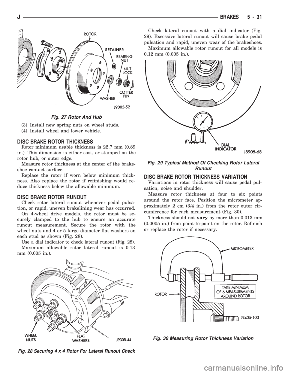
(3) Remove retainers securing rotor to hub studs
(Fig. 27).
(4) Remove rotor from hub (Fig. 27).
(5) If rotor shield requires service, remove front
hub and bearing assembly.
ROTOR INSTALLATION
(1) Install rotor on hub.
(2) Install caliper.
Fig. 24 Typical Caliper/Piston Areas To Be Lightly
Coated With Silicone Grease
Fig. 25 Seating Caliper Piston Piston Dust Boot
Fig. 26 Front Brake Hose And Fitting Components
5 - 30 BRAKESJ
Page 178 of 1784
(3) Install new spring nuts on wheel studs.
(4) Install wheel and lower vehicle.
DISC BRAKE ROTOR THICKNESS
Rotor minimum usable thickness is 22.7 mm (0.89
in.). This dimension is either cast, or stamped on the
rotor hub, or outer edge.
Measure rotor thickness at the center of the brake-
shoe contact surface.
Replace the rotor if worn below minimum thick-
ness. Also replace the rotor if refinishing would re-
duce thickness below the allowable minimum.
DISC BRAKE ROTOR RUNOUT
Check rotor lateral runout whenever pedal pulsa-
tion, or rapid, uneven brakelining wear has occurred.
On 4-wheel drive models, the rotor must be se-
curely clamped to the hub to ensure an accurate
runout measurement. Secure the rotor with the
wheel nuts and 4 or 5 large diameter flat washers on
each stud as shown (Fig. 28).
Use a dial indicator to check lateral runout (Fig. 28).
Maximum allowable rotor lateral runout is 0.13
mm (0.005 in.).Check lateral runout with a dial indicator (Fig.
29). Excessive lateral runout will cause brake pedal
pulsation and rapid, uneven wear of the brakeshoes.
Maximum allowable rotor runout for all models is
0.12 mm (0.005 in.).
DISC BRAKE ROTOR THICKNESS VARIATION
Variations in rotor thickness will cause pedal pul-
sation, noise and shudder.
Measure rotor thickness at four to six points
around the rotor face. Position the micrometer ap-
proximately 2 cm (3/4 in.) from the rotor outer cir-
cumference for each measurement (Fig. 30).
Thickness should notvaryby more than 0.013 mm
(0.0005 in.) from point-to-point on the rotor. Refinish
or replace the rotor if necessary.
Fig. 27 Rotor And Hub
Fig. 28 Securing4x4Rotor For Lateral Runout Check
Fig. 29 Typical Method Of Checking Rotor Lateral
Runout
Fig. 30 Measuring Rotor Thickness Variation
JBRAKES 5 - 31
Page 179 of 1784
DISC BRAKE ROTOR REFINISHING
When To Refinish
Rotor braking surfaces can be refinished by sand-
ing and/or machining in a disc brake lathe. However,
the rotor should be cleaned and inspected before-
hand. Careful inspection will avoid refinishing rotors
with very little service life left in them.
Pay particular attention to rotors that are heavily
rusted, or corroded. Accumulated rust/corrosion on
braking surfaces and ventilating ribs may extend to
a depth beyond acceptable limits. This can be espe-cially true on: (a) high mileage vehicles; (b) vehicles
regularly exposed to road salt during winter months;
(c) vehicles operated in coastal regions where salt
air/road splash is a factor; (d) and vehicles used for
extensive off-road operation.
Recommended Refinishing Equipment
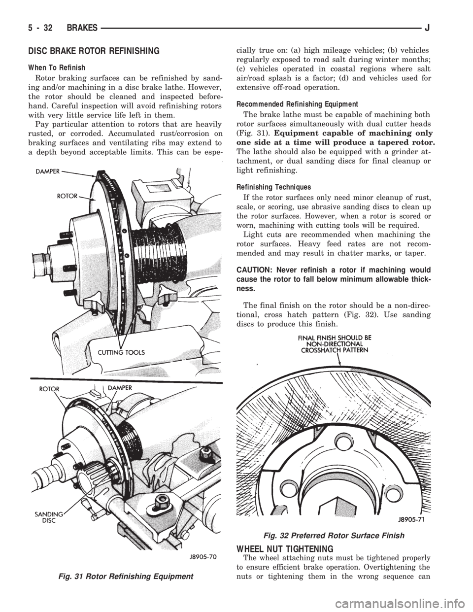
The brake lathe must be capable of machining both
rotor surfaces simultaneously with dual cutter heads
(Fig. 31).Equipment capable of machining only
one side at a time will produce a tapered rotor.
The lathe should also be equipped with a grinder at-
tachment, or dual sanding discs for final cleanup or
light refinishing.
Refinishing Techniques
If the rotor surfaces only need minor cleanup of rust,
scale, or scoring, use abrasive sanding discs to clean up
the rotor surfaces. However, when a rotor is scored or
worn, machining with cutting tools will be required.
Light cuts are recommended when machining the
rotor surfaces. Heavy feed rates are not recom-
mended and may result in chatter marks, or taper.
CAUTION: Never refinish a rotor if machining would
cause the rotor to fall below minimum allowable thick-
ness.
The final finish on the rotor should be a non-direc-
tional, cross hatch pattern (Fig. 32). Use sanding
discs to produce this finish.
WHEEL NUT TIGHTENING
The wheel attaching nuts must be tightened properly
to ensure efficient brake operation. Overtightening the
nuts or tightening them in the wrong sequence can
Fig. 31 Rotor Refinishing Equipment
Fig. 32 Preferred Rotor Surface Finish
5 - 32 BRAKESJ
Page 180 of 1784
cause distortion of the brake rotors and drums.
Impact wrenches are not recommended for tighten-
ing wheel nuts. A torque wrench should be used for
this purpose.
A light coat of LPS Anti-Corrosion spray lube
around the hub face and on the studs will cut down
on rust/corrosion formation.
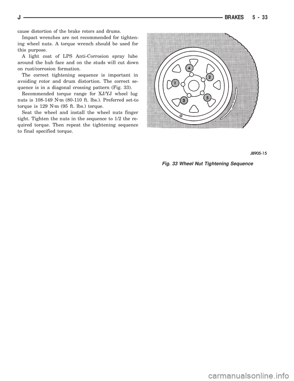
The correct tightening sequence is important in
avoiding rotor and drum distortion. The correct se-
quence is in a diagonal crossing pattern (Fig. 33).
Recommended torque range for XJ/YJ wheel lug
nuts is 108-149 Nzm (80-110 ft. lbs.). Preferred set-to
torque is 129 Nzm (95 ft. lbs.) torque.
Seat the wheel and install the wheel nuts finger
tight. Tighten the nuts in the sequence to 1/2 the re-
quired torque. Then repeat the tightening sequence
to final specified torque.
Fig. 33 Wheel Nut Tightening Sequence
JBRAKES 5 - 33