JEEP CHEROKEE 1994 Service Repair Manual
Manufacturer: JEEP, Model Year: 1994, Model line: CHEROKEE, Model: JEEP CHEROKEE 1994Pages: 1784, PDF Size: 77.09 MB
Page 381 of 1784
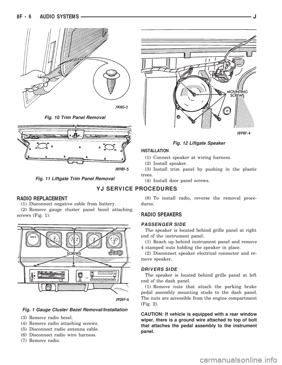
INSTALLATION
(1) Connect speaker at wiring harness.
(2) Install speaker.
(3) Install trim panel by pushing in the plastic
trees.
(4) Install door panel screws.
YJ SERVICE PROCEDURES
RADIO REPLACEMENT
(1) Disconnect negative cable from battery.
(2) Remove gauge cluster panel bezel attaching
screws (Fig. 1).
(3) Remove radio bezel.
(4) Remove radio attaching screws.
(5) Disconnect radio antenna cable.
(6) Disconnect radio wire harness.
(7) Remove radio.(8) To install radio, reverse the removal proce-
dures.
RADIO SPEAKERS
PASSENGER SIDE
The speaker is located behind grille panel at right
end of the instrument panel.
(1) Reach up behind instrument panel and remove
4 stamped nuts holding the speaker in place.
(2) Disconnect speaker electrical connector and re-
move speaker.
DRIVERS SIDE
The speaker is located behind grille panel at left
end of the dash panel.
(1) Remove nuts that attach the parking brake
pedal assembly mounting studs to the dash panel.
The nuts are accessible from the engine compartment
(Fig. 2).
CAUTION: If vehicle is equipped with a rear window
wiper, there is a ground wire attached to top of bolt
that attaches the pedal assembly to the instrument
panel.
Fig. 10 Trim Panel Removal
Fig. 11 Liftgate Trim Panel Removal
Fig. 12 Liftgate Speaker
Fig. 1 Gauge Cluster Bezel Removal/Installation
8F - 6 AUDIO SYSTEMSJ
Page 382 of 1784
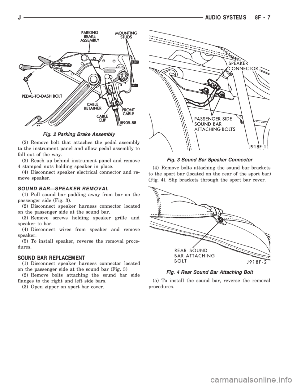
(2) Remove bolt that attaches the pedal assembly
to the instrument panel and allow pedal assembly to
fall out of the way.
(3) Reach up behind instrument panel and remove
4 stamped nuts holding speaker in place.
(4) Disconnect speaker electrical connector and re-
move speaker.
SOUND BARÐSPEAKER REMOVAL
(1) Pull sound bar padding away from bar on the
passenger side (Fig. 3).
(2) Disconnect speaker harness connector located
on the passenger side at the sound bar.
(3) Remove screws holding speaker grille and
speaker to bar.
(4) Disconnect wires from speaker and remove
speaker.
(5) To install speaker, reverse the removal proce-
dures.
SOUND BAR REPLACEMENT
(1) Disconnect speaker harness connector located
on the passenger side at the sound bar (Fig. 3)
(2) Remove bolts attaching the sound bar side
flanges to the right and left side bars.
(3) Open zipper on sport bar cover.(4) Remove bolts attaching the sound bar brackets
to the sport bar (located on the rear of the sport bar)
(Fig. 4). Slip brackets through the sport bar cover.
(5) To install the sound bar, reverse the removal
procedures.
Fig. 2 Parking Brake Assembly
Fig. 3 Sound Bar Speaker Connector
Fig. 4 Rear Sound Bar Attaching Bolt
JAUDIO SYSTEMS 8F - 7
Page 383 of 1784
RADIO ANTENNA
INDEX
page page
Antenna Tests............................ 9
General Information........................ 8Replacement............................. 8
GENERAL INFORMATION
AM/FM radio model antennas must have a good
ground to eliminate static. The antenna mast is con-
nected to the inner wire of the coaxial cable and is
not grounded to any part of the vehicle. The coaxial
shield (the wire mesh) surrounding the center con-
ductor wire of the antenna lead-in cable is grounded
to the radio and the antenna base.
REPLACEMENT
XJ
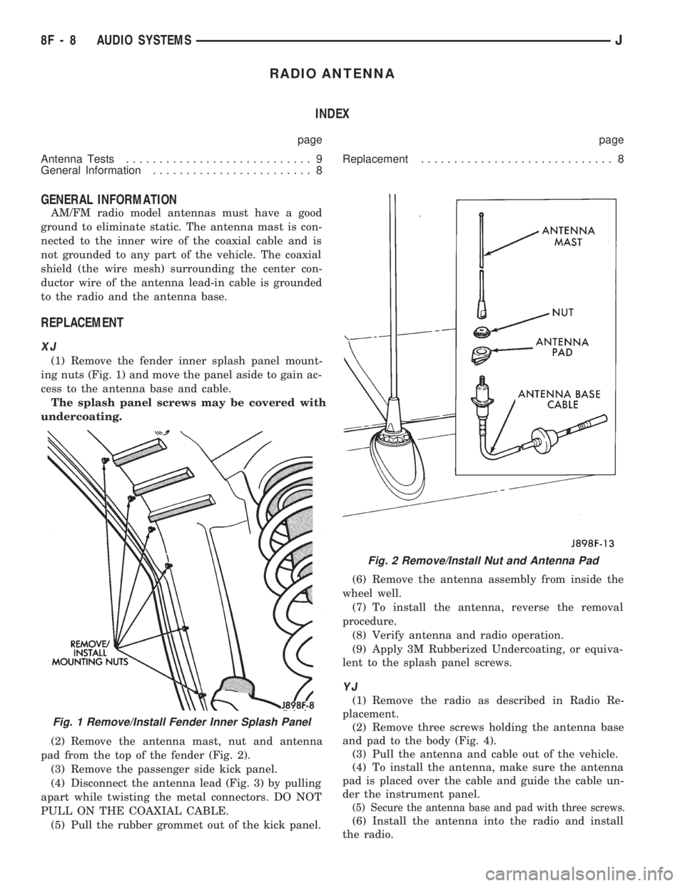
(1) Remove the fender inner splash panel mount-
ing nuts (Fig. 1) and move the panel aside to gain ac-
cess to the antenna base and cable.
The splash panel screws may be covered with
undercoating.
(2) Remove the antenna mast, nut and antenna
pad from the top of the fender (Fig. 2).
(3) Remove the passenger side kick panel.
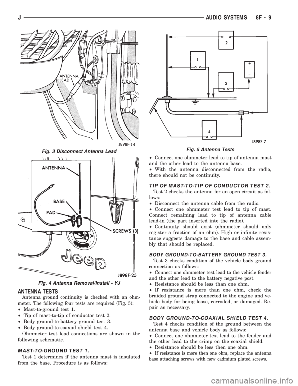
(4) Disconnect the antenna lead (Fig. 3) by pulling
apart while twisting the metal connectors. DO NOT
PULL ON THE COAXIAL CABLE.
(5) Pull the rubber grommet out of the kick panel.(6) Remove the antenna assembly from inside the
wheel well.
(7) To install the antenna, reverse the removal
procedure.
(8) Verify antenna and radio operation.
(9) Apply 3M Rubberized Undercoating, or equiva-
lent to the splash panel screws.
YJ
(1) Remove the radio as described in Radio Re-
placement.
(2) Remove three screws holding the antenna base
and pad to the body (Fig. 4).
(3) Pull the antenna and cable out of the vehicle.
(4) To install the antenna, make sure the antenna
pad is placed over the cable and guide the cable un-
der the instrument panel.
(5) Secure the antenna base and pad with three screws.
(6) Install the antenna into the radio and install
the radio.
Fig. 1 Remove/Install Fender Inner Splash Panel
Fig. 2 Remove/Install Nut and Antenna Pad
8F - 8 AUDIO SYSTEMSJ
Page 384 of 1784
ANTENNA TESTS
Antenna ground continuity is checked with an ohm-
meter. The following four tests are required (Fig. 5):
²Mast-to-ground test 1.
²Tip of mast-to-tip of conductor test 2.
²Body ground-to-battery ground test 3.
²Body ground-to-coaxial shield test 4.
Ohmmeter test lead connections are shown in the
following schematic.
MAST-TO-GROUND TEST 1.
Test 1 determines if the antenna mast is insulated
from the base. Procedure is as follows:²Connect one ohmmeter lead to tip of antenna mast
and the other lead to the antenna base.
²With the antenna disconnected from the radio,
there should not be continuity.
TIP OF MAST-TO-TIP OF CONDUCTOR TEST 2.
Test 2 checks the antenna for an open circuit as fol-
lows:
²Disconnect the antenna cable from the radio.
²Connect one ohmmeter test lead to tip of mast.
Connect remaining lead to tip of antenna cable
lead-in (the part inserted into the radio).
²Continuity should exist (ohmmeter should only
register a fraction of an ohm). High or infinite resis-
tance suggests damage to the base and cable assem-
bly that should be replaced.
BODY GROUND-TO-BATTERY GROUND TEST 3.
Test 3 checks condition of the vehicle body ground
connection as follows:
²
Connect one ohmmeter test lead to the vehicle fender
and the other lead to the battery negative post.
²Resistance should be less than one ohm.
²If resistance is more than one ohm, check the
braided ground strap connected to the engine and ve-
hicle body for being loose, corroded, or damaged. Re-
pair as necessary.
BODY GROUND-TO-COAXIAL SHIELD TEST 4.
Test 4 checks condition of the ground between the
antenna base and vehicle body as follows:
²Connect one ohmmeter test lead to the fender and
the other lead to the crimp on the coaxial shield.
²Resistance should be less then one ohm.
²
If resistance is more then one ohm, replace the antenna
base attaching screws with new cadmium plated screws.
Fig. 3 Disconnect Antenna Lead
Fig. 4 Antenna Removal/Install - YJ
Fig. 5 Antenna Tests
JAUDIO SYSTEMS 8F - 9
Page 385 of 1784

Page 386 of 1784
HORNS
CONTENTS
page page
GENERAL INFORMATION.................. 1
HORN SWITCH (HORN PAD) REPLACEMENT . . 3
TORQUE SPECIFICATIONS................. 3XJ ..................................... 1
YJ ..................................... 2
GENERAL INFORMATION
For XJ/YJ vehicles battery voltage is applied to the
horn relay through a fuse.
When the horn switch is depressed, the horn relay
is grounded, pulling the contact closed and providing
battery voltage to the horns.
A slip ring and brush arrangement in the steering
wheel allows the switch circuit to maintain contact
while allowing rotation of the steering wheel.On XJ models, a cadmium-plated ground
screw is used to attach the horn(s) to the body.
Do not substitute other types of ground screws
as they may become corroded and cause a loss
of ground.
XJ
REPLACEMENT
(1) Raise and support the vehicle.
(2) Remove the splash shield.
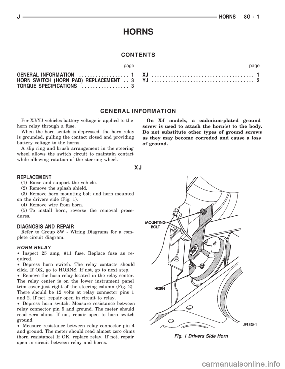
(3) Remove horn mounting bolt and horn mounted
on the drivers side (Fig. 1).
(4) Remove wire from horn.
(5) To install horn, reverse the removal proce-
dures.
DIAGNOSIS AND REPAIR
Refer to Group 8W - Wiring Diagrams for a com-
plete circuit diagram.
HORN RELAY
²Inspect 25 amp, #11 fuse. Replace fuse as re-
quired.
²Depress horn switch. The relay contacts should
click. If OK, go to HORNS. If not, go to next step.
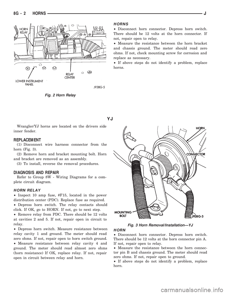
²Remove the horn relay located in the relay center.
The relay center is on the lower instrument panel
trim cover just right of the steering column (Fig. 2).
There should be 12 volts at relay connector pins 1
and 2. If not, repair open in circuit to relay.
²Depress horn switch. Measure resistance between
relay connector pin 5 and ground. The meter should
read zero ohms. If not, repair open to horn switch
ground.
²Measure resistance between relay connector pin 4
and ground. The meter should read almost zero ohms
(horn resistance) If OK, replace relay. If not, repair
open in circuit between relay and horns.
Fig. 1 Drivers Side Horn
JHORNS 8G - 1
Page 387 of 1784
HORNS
²Disconnect horn connector. Depress horn switch.
There should be 12 volts at the horn connector. If
not, repair open to relay.
²Measure the resistance between the horn bracket
and chassis ground. The meter should read zero
ohms. If not, check mounting screw for corrosion and
replace as necessary.
²If above steps do not identify a problem, replace
horns.
YJ
Wrangler/YJ horns are located on the drivers side
inner fender.
REPLACEMENT
(1) Disconnect wire harness connector from the
horn (Fig. 3).
(2) Remove horn and bracket mounting bolt. Horn
and bracket are removed as an assembly.
(3) To install, reverse the removal procedures.
DIAGNOSIS AND REPAIR
Refer to Group 8W - Wiring Diagrams for a com-
plete circuit diagram.
HORN RELAY
²Inspect 10 amp fuse, #F15, located in the power
distribution center (PDC). Replace fuse as required.
²Depress horn switch. The relay contacts should
click. If OK, go to HORN. If not, go to next step.
²Remove relay from PDC. There should be 12 volts
at cavities 2 and 5. If not, repair open in circuit to
relay.
²Depress horn switch. Measure resistance between
relay cavity 1 and ground. The meter should read
zero ohms. If not, repair open to horn switch ground.
²Measure resistance between relay cavity 4 and
ground. The meter should read almost zero ohms
(horn resistance) If OK, replace relay. If not, repair
open in circuit between relay and horn.
HORN
²Disconnect horn connector. Depress horn switch.
There should be 12 volts at the horn connector pin A.
If not, repair open to relay.
²Measure the resistance between the horn connec-
tor pin B and chassis ground. The meter should read
zero ohms. If not, repair open to ground.
²If above steps do not identify a problem, replace
horn.
Fig. 2 Horn Relay
Fig. 3 Horn Removal/InstallationÐYJ
8G - 2 HORNSJ
Page 388 of 1784
HORN SWITCH (HORN PAD) REPLACEMENT
(1) Disconnect negative cable from battery.
(2) Remove horn button by pulling straight up.
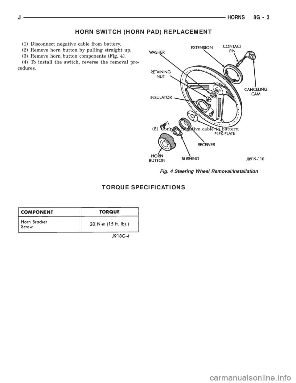
(3) Remove horn button components (Fig. 4).
(4) To install the switch, reverse the removal pro-
cedures.
(5) Connect negative cable to battery.
TORQUE SPECIFICATIONS
Fig. 4 Steering Wheel Removal/Installation
JHORNS 8G - 3
Page 389 of 1784

Page 390 of 1784
VEHICLE SPEED CONTROL SYSTEM
CONTENTS
page page
SERVICE PROCEDURES................... 9TEST PROCEDURES...................... 5
GENERAL INFORMATION
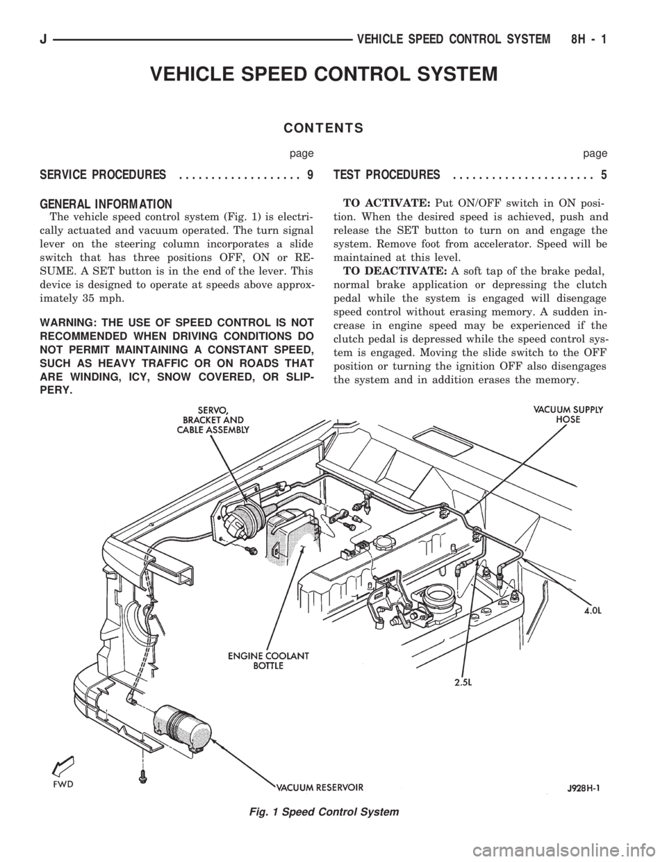
The vehicle speed control system (Fig. 1) is electri-
cally actuated and vacuum operated. The turn signal
lever on the steering column incorporates a slide
switch that has three positions OFF, ON or RE-
SUME. A SET button is in the end of the lever. This
device is designed to operate at speeds above approx-
imately 35 mph.
WARNING: THE USE OF SPEED CONTROL IS NOT
RECOMMENDED WHEN DRIVING CONDITIONS DO
NOT PERMIT MAINTAINING A CONSTANT SPEED,
SUCH AS HEAVY TRAFFIC OR ON ROADS THAT
ARE WINDING, ICY, SNOW COVERED, OR SLIP-
PERY.TO ACTIVATE:Put ON/OFF switch in ON posi-
tion. When the desired speed is achieved, push and
release the SET button to turn on and engage the
system. Remove foot from accelerator. Speed will be
maintained at this level.
TO DEACTIVATE:A soft tap of the brake pedal,
normal brake application or depressing the clutch
pedal while the system is engaged will disengage
speed control without erasing memory. A sudden in-
crease in engine speed may be experienced if the
clutch pedal is depressed while the speed control sys-
tem is engaged. Moving the slide switch to the OFF
position or turning the ignition OFF also disengages
the system and in addition erases the memory.
Fig. 1 Speed Control System
JVEHICLE SPEED CONTROL SYSTEM 8H - 1