JEEP CHEROKEE 1994 Service Repair Manual
Manufacturer: JEEP, Model Year: 1994, Model line: CHEROKEE, Model: JEEP CHEROKEE 1994Pages: 1784, PDF Size: 77.09 MB
Page 341 of 1784
INSTALLATION
(1) Install MAP sensor to dash panel and secure
with mounting nuts.
(2) Install the MAP sensor vacuum supply hose.
(3) Connect the MAP sensor electrical connector.
OXYGEN (O2S) SENSOR
For diagnostics and removal/installation proce-
dures, refer to Group 14, Fuel Systems, in this man-
ual.
POWERTRAIN CONTROL MODULE (PCM)
The PCM was formerly referred to as the SBEC or
engine controller.
XJ MODELS
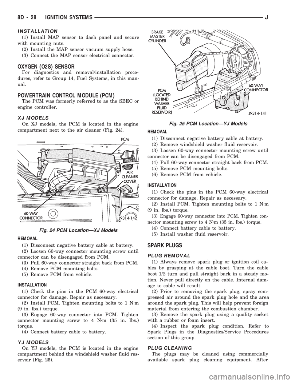
On XJ models, the PCM is located in the engine
compartment next to the air cleaner (Fig. 24).
REMOVAL
(1) Disconnect negative battery cable at battery.
(2) Loosen 60-way connector mounting screw until
connector can be disengaged from PCM.
(3) Pull 60-way connector straight back from PCM.
(4) Remove PCM mounting bolts.
(5) Remove PCM from vehicle.
INSTALLATION
(1) Check the pins in the PCM 60-way electrical
connector for damage. Repair as necessary.
(2) Install PCM. Tighten mounting bolts to 1 Nzm
(9 in. lbs.) torque.
(3) Engage 60-way connector into PCM. Tighten
connector mounting screw to 4 Nzm (35 in. lbs.)
torque.
(4) Connect battery cable to battery.
YJ MODELS
On YJ models, the PCM is located in the engine
compartment behind the windshield washer fluid res-
ervoir (Fig. 25).REMOVAL
(1) Disconnect negative battery cable at battery.
(2) Remove windshield washer fluid reservoir.
(3) Loosen 60-way connector mounting screw until
connector can be disengaged from PCM.
(4) Pull 60-way connector straight back from PCM.
(5) Remove PCM mounting bolts.
(6) Remove PCM from vehicle.
INSTALLATION
(1) Check the pins in the PCM 60-way electrical
connector for damage. Repair as necessary.
(2) Install PCM. Tighten mounting bolts to 1 Nzm
(9 in. lbs.) torque.
(3) Engage 60-way connector into PCM. Tighten con-
nector mounting screw to 4 Nzm (35 in. lbs.) torque.
(4) Connect battery cable to battery.
(5) Install washer fluid reservoir.
SPARK PLUGS
PLUG REMOVAL
(1) Always remove spark plug or ignition coil ca-
bles by grasping at the cable boot. Turn the cable
boot 1/2 turn and pull straight back in a steady mo-
tion. Never pull directly on the cable. Internal dam-
age to cable will result.
(2) Prior to removing the spark plug, spray com-
pressed air around the spark plug hole and the area
around the spark plug. This will help prevent foreign
material from entering the combustion chamber.
(3) Remove the spark plug using a quality socket
with a rubber or foam insert.
(4) Inspect the spark plug condition. Refer to
Spark Plugs in the Diagnostics/Service Procedures
section of this group.
PLUG CLEANING
The plugs may be cleaned using commercially
available spark plug cleaning equipment. After
Fig. 24 PCM LocationÐXJ Models
Fig. 25 PCM LocationÐYJ Models
8D - 28 IGNITION SYSTEMSJ
Page 342 of 1784
cleaning, file the center electrode flat with a small
point file or jewelers file before adjusting gap.
PLUG GAP ADJUSTMENT
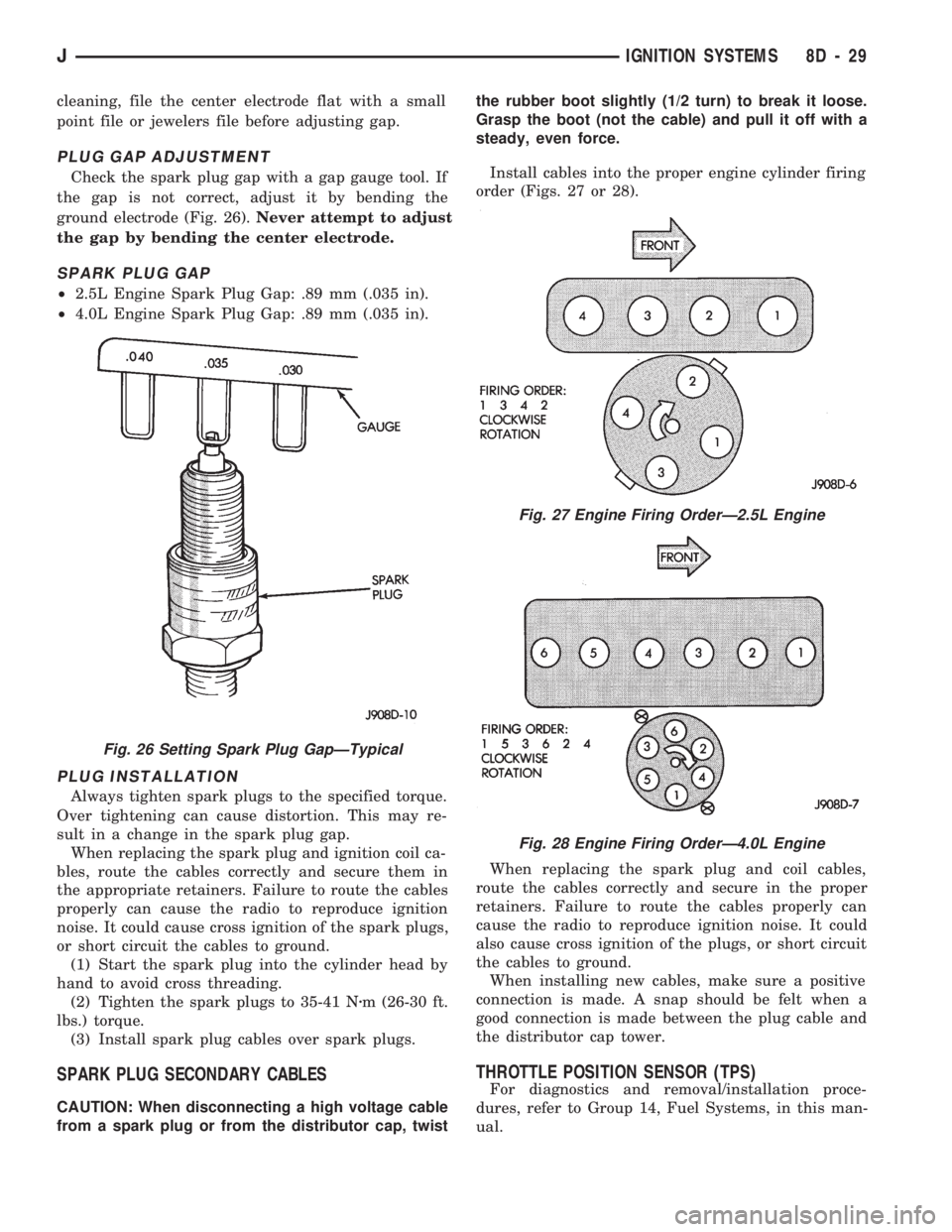
Check the spark plug gap with a gap gauge tool. If
the gap is not correct, adjust it by bending the
ground electrode (Fig. 26).Never attempt to adjust
the gap by bending the center electrode.
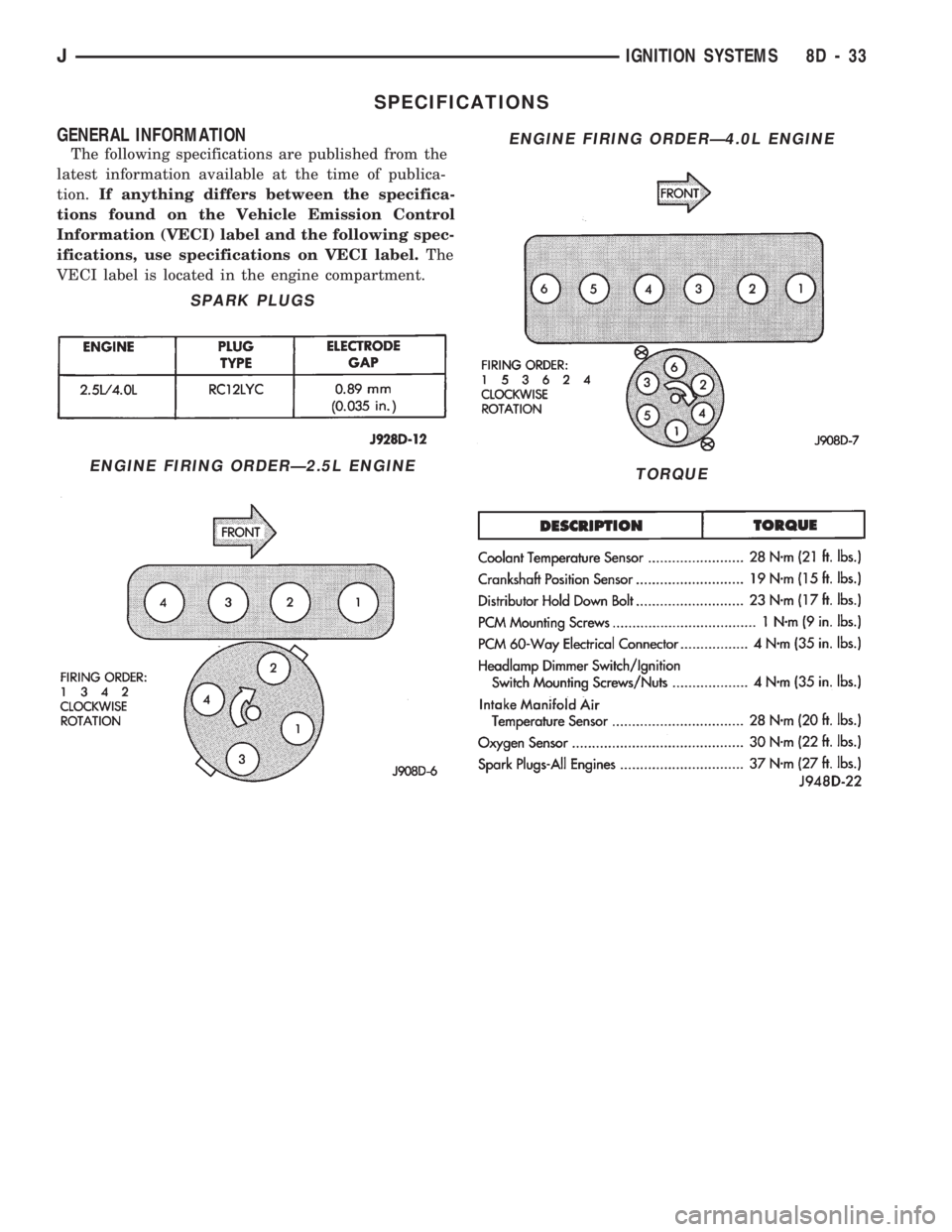
SPARK PLUG GAP
²2.5L Engine Spark Plug Gap: .89 mm (.035 in).
²4.0L Engine Spark Plug Gap: .89 mm (.035 in).
PLUG INSTALLATION
Always tighten spark plugs to the specified torque.
Over tightening can cause distortion. This may re-
sult in a change in the spark plug gap.
When replacing the spark plug and ignition coil ca-
bles, route the cables correctly and secure them in
the appropriate retainers. Failure to route the cables
properly can cause the radio to reproduce ignition
noise. It could cause cross ignition of the spark plugs,
or short circuit the cables to ground.
(1) Start the spark plug into the cylinder head by
hand to avoid cross threading.
(2) Tighten the spark plugs to 35-41 Nzm (26-30 ft.
lbs.) torque.
(3) Install spark plug cables over spark plugs.
SPARK PLUG SECONDARY CABLES
CAUTION: When disconnecting a high voltage cable
from a spark plug or from the distributor cap, twistthe rubber boot slightly (1/2 turn) to break it loose.
Grasp the boot (not the cable) and pull it off with a
steady, even force.
Install cables into the proper engine cylinder firing
order (Figs. 27 or 28).
When replacing the spark plug and coil cables,
route the cables correctly and secure in the proper
retainers. Failure to route the cables properly can
cause the radio to reproduce ignition noise. It could
also cause cross ignition of the plugs, or short circuit
the cables to ground.
When installing new cables, make sure a positive
connection is made. A snap should be felt when a
good connection is made between the plug cable and
the distributor cap tower.
THROTTLE POSITION SENSOR (TPS)
For diagnostics and removal/installation proce-
dures, refer to Group 14, Fuel Systems, in this man-
ual.
Fig. 26 Setting Spark Plug GapÐTypical
Fig. 27 Engine Firing OrderÐ2.5L Engine
Fig. 28 Engine Firing OrderÐ4.0L Engine
JIGNITION SYSTEMS 8D - 29
Page 343 of 1784
IGNITION SWITCH
INDEX
page page
General Information....................... 30
Ignition Switch Installation/Adjustment......... 31Ignition Switch Removal................... 30
Ignition Switch Testing..................... 30
GENERAL INFORMATION
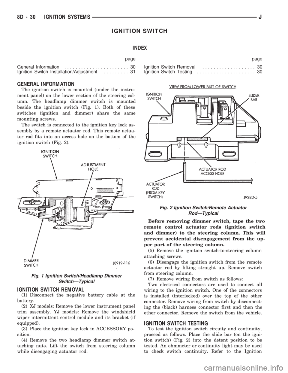
The ignition switch is mounted (under the instru-
ment panel) on the lower section of the steering col-
umn. The headlamp dimmer switch is mounted
beside the ignition switch (Fig. 1). Both of these
switches (ignition and dimmer) share the same
mounting screws.
The switch is connected to the ignition key lock as-
sembly by a remote actuator rod. This remote actua-
tor rod fits into an access hole on the bottom of the
ignition switch (Fig. 2).
IGNITION SWITCH REMOVAL
(1) Disconnect the negative battery cable at the
battery.
(2) XJ models: Remove the lower instrument panel
trim assembly. YJ models: Remove the windshield
wiper intermittent control module and its bracket (if
equipped).
(3) Place the ignition key lock in ACCESSORY po-
sition.
(4) Remove the two headlamp dimmer switch at-
taching nuts. Lift the switch from steering column
while disengaging actuator rod.Before removing dimmer switch, tape the two
remote control actuator rods (ignition switch
and dimmer) to the steering column. This will
prevent accidental disengagement from the up-
per part of the steering column.
(5) Remove the ignition switch-to-steering column
attaching screws.
(6) Disengage the ignition switch from the remote
actuator rod by lifting straight up. Remove switch
from steering column.
(7) Remove wiring from switch as follows:
Two electrical connectors are used to connect all
wiring to the ignition switch. One of the connectors
is installed (interlocked) over the top of the other
connector. Remove wiring from switch by disconnect-
ing the (black) harness connector first and then the
other connector. Remove the switch from the vehicle.
IGNITION SWITCH TESTING
To test the ignition switch circuity and continuity,
proceed as follows. Place the slide bar (on the igni-
tion switch) (Fig. 2) into the detent position to be
tested. An ohmmeter or continuity light may be used
to check switch continuity. Refer to the Ignition
Fig. 1 Ignition Switch/Headlamp Dimmer
SwitchÐTypical
Fig. 2 Ignition Switch/Remote Actuator
RodÐTypical
8D - 30 IGNITION SYSTEMSJ
Page 344 of 1784
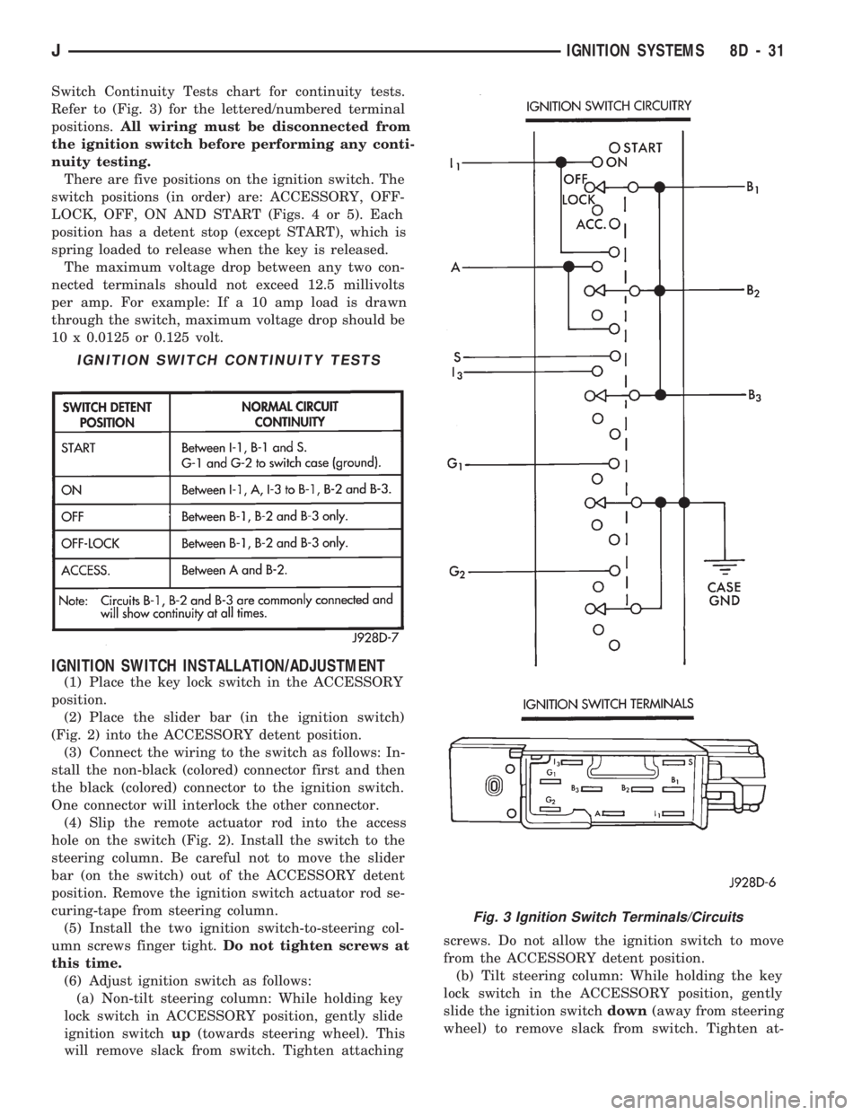
Switch Continuity Tests chart for continuity tests.
Refer to (Fig. 3) for the lettered/numbered terminal
positions.All wiring must be disconnected from
the ignition switch before performing any conti-
nuity testing.
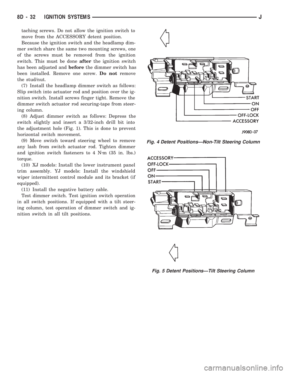
There are five positions on the ignition switch. The
switch positions (in order) are: ACCESSORY, OFF-
LOCK, OFF, ON AND START (Figs. 4 or 5). Each
position has a detent stop (except START), which is
spring loaded to release when the key is released.
The maximum voltage drop between any two con-
nected terminals should not exceed 12.5 millivolts
per amp. For example: If a 10 amp load is drawn
through the switch, maximum voltage drop should be
10 x 0.0125 or 0.125 volt.
IGNITION SWITCH INSTALLATION/ADJUSTMENT
(1) Place the key lock switch in the ACCESSORY
position.
(2) Place the slider bar (in the ignition switch)
(Fig. 2) into the ACCESSORY detent position.
(3) Connect the wiring to the switch as follows: In-
stall the non-black (colored) connector first and then
the black (colored) connector to the ignition switch.
One connector will interlock the other connector.
(4) Slip the remote actuator rod into the access
hole on the switch (Fig. 2). Install the switch to the
steering column. Be careful not to move the slider
bar (on the switch) out of the ACCESSORY detent
position. Remove the ignition switch actuator rod se-
curing-tape from steering column.
(5) Install the two ignition switch-to-steering col-
umn screws finger tight.Do not tighten screws at
this time.
(6) Adjust ignition switch as follows:
(a) Non-tilt steering column: While holding key
lock switch in ACCESSORY position, gently slide
ignition switchup(towards steering wheel). This
will remove slack from switch. Tighten attachingscrews. Do not allow the ignition switch to move
from the ACCESSORY detent position.
(b) Tilt steering column: While holding the key
lock switch in the ACCESSORY position, gently
slide the ignition switchdown(away from steering
wheel) to remove slack from switch. Tighten at-
IGNITION SWITCH CONTINUITY TESTS
Fig. 3 Ignition Switch Terminals/Circuits
JIGNITION SYSTEMS 8D - 31
Page 345 of 1784
taching screws. Do not allow the ignition switch to
move from the ACCESSORY detent position.
Because the ignition switch and the headlamp dim-
mer switch share the same two mounting screws, one
of the screws must be removed from the ignition
switch. This must be doneafterthe ignition switch
has been adjusted andbeforethe dimmer switch has
been installed. Remove one screw.Do notremove
the stud/nut.
(7) Install the headlamp dimmer switch as follows:
Slip switch into actuator rod and position over the ig-
nition switch. Install screws finger tight. Remove the
dimmer switch actuator rod securing-tape from steer-
ing column.
(8) Adjust dimmer switch as follows: Depress the
switch slightly and insert a 3/32-inch drill bit into
the adjustment hole (Fig. 1). This is done to prevent
horizontal switch movement.
(9) Move switch toward steering wheel to remove
any lash from switch actuator rod. Tighten dimmer
and ignition switch fasteners to 4 Nzm (35 in. lbs.)
torque.
(10) XJ models: Install the lower instrument panel
trim assembly. YJ models: Install the windshield
wiper intermittent control module and its bracket (if
equipped).
(11) Install the negative battery cable.
Test dimmer switch. Test ignition switch operation
in all switch positions. If equipped with a tilt steer-
ing column, test operation of dimmer switch and ig-
nition switch in all tilt positions.
Fig. 4 Detent PositionsÐNon-Tilt Steering Column
Fig. 5 Detent PositionsÐTilt Steering Column
8D - 32 IGNITION SYSTEMSJ
Page 346 of 1784
SPECIFICATIONS
GENERAL INFORMATION
The following specifications are published from the
latest information available at the time of publica-
tion.If anything differs between the specifica-
tions found on the Vehicle Emission Control
Information (VECI) label and the following spec-
ifications, use specifications on VECI label.The
VECI label is located in the engine compartment.
SPARK PLUGS
ENGINE FIRING ORDERÐ2.5L ENGINE
ENGINE FIRING ORDERÐ4.0L ENGINE
TORQUE
JIGNITION SYSTEMS 8D - 33
Page 347 of 1784

Page 348 of 1784
INSTRUMENT PANEL AND GAUGES
GROUP INDEX
page page
INSTRUMENT PANEL AND GAUGESÐXJ..... 1INSTRUMENT PANEL AND GAUGESÐYJ.... 14
INSTRUMENT PANEL AND GAUGESÐXJE
CONTENTS
page page
INSTRUMENT CLUSTER DIAGNOSIS........ 3
INSTRUMENT CLUSTER GENERAL INFORMATION.. 1
INSTRUMENT CLUSTER SERVICE PROCEDURES... 5
SPECIFICATIONS....................... 13
INSTRUMENT CLUSTER GENERAL INFORMATION
INDEX
page page
4WD Indicator Lamp........................ 2
Anti-Lock Brake Indicator Lamp............... 2
Brake Indicator Lamp....................... 2
Coolant Temperature Gauge................. 1
Coolant Temperature Indicator Lamp........... 1
Fuel Gauge.............................. 2
Low Fuel Warning Lamp..................... 2Malfunction Indicator Lamp (Check Engine)...... 2
Oil Pressure Gauge....................... 1
Oil Pressure Indicator Lamp.................. 1
Speedometer/Odometer System.............. 2
Tachometer.............................. 2
Upshift Indicator Lamp...................... 2
Voltmeter............................... 1
With the ignition switch in the ON or START posi-
tion, voltage supplied to the instrument cluster is lim-
ited by fuse #17. The voltage is supplied to all the
gauges and indicator lamps through the instrument
cluster printed circuit.
With the ignition switch in the OFF position, volt-
age is not supplied to the instrument cluster and the
gauges do not indicate any vehicle condition.
VOLTMETER
The voltmeter measures battery or generator out-
put voltage, whichever is greater.
OIL PRESSURE GAUGE
The oil pressure gauge pointer position is controlled
by a magnetic field created by electrical current flow
through the coils within the gauge. A change in current
flow will change the magnetic field which changes the
pointer position. The oil pressure sender is a variable
resistor that changes electrical resistance with a change
in oil pressure (values shown in Specifications chart).
OIL PRESSURE INDICATOR LAMP
Voltage is supplied to one side of the indicator bulb
and the oil pressure switch is connected to the other
side. When oil pressure is too low the switch closes
providing a path to ground, and the indicator bulb
lights.
COOLANT TEMPERATURE GAUGE
The coolant temperature gauge pointer position is
controlled by a magnetic field created by electrical
current flow through the coils within the gauge. A
change in current flow will change the magnetic field
which changes the pointer position. The coolant tem-
perature sensor is a thermistor that changes electri-
cal resistance with a change in coolant temperature
(values shown in Specifications chart).
COOLANT TEMPERATURE INDICATOR LAMP
Voltage is supplied to one side of the indicator bulb
and the coolant temperature switch is connected to the
JINSTRUMENT PANEL AND GAUGES 8E - 1
Page 349 of 1784
other side. When coolant temperature is too high the
switch closes providing a path to ground, and the indi-
cator bulb lights.
TACHOMETER
The tachometer displays the engine speed (RPM).
With the engine running, the tachometer receives an
engine speed signal from the Powertrain Control
Module pin 43 (values shown in Specifications chart).
SPEEDOMETER/ODOMETER SYSTEM
The speedometer/odometer system consists of an elec-
tric speedometer and pushbutton reset odometer
mounted in the cluster. The system also includes the
wire harness from the cluster to the vehicle speed sen-
sor at the transmission, and the adapter and pinion in
the transmission. A signal is sent from a transmission
mounted vehicle speed sensor to the speedometer/odom-
eter circuitry through the wiring harness. Refer to
Group 21 - Transmission for selecting the proper pinion,
and selecting and indexing the proper adapter.
FUEL GAUGE
The fuel gauge pointer position is controlled by a
magnetic field created by electrical current flow through
the coils within the gauge. A change in current flow will
change the magnetic field which changes the pointer po-
sition. The fuel level sender is a variable resistor that
changes electrical resistance with a change of the level
of fuel in the tank (values shown in Specifications
chart).
LOW FUEL WARNING LAMP
The low fuel warning lamp will light when the fuel
level falls below approximately 4 gallons. A low fuel
warning module controls when the lamp will light.
When the module senses 66.5 ohms or less from the
fuel level sender for 10 continuous seconds, the lamp
will light. The lamp will remain on until the module
senses 63.5 ohms or more from the fuel level sender
for 20 continuous seconds.
UPSHIFT INDICATOR LAMP
Vehicles equipped with manual transmissions have an
optional upshift indicator lamp. The lamp is controlled
by the Powertrain Control Module. The lamp lights to
indicate when the driver should shift to the next high-
est gear for best fuel economy. The Powertrain Control
Module will turn the lamp off after 3 to 5 seconds if the
upshift is not performed. The lamp will remain off until
the vehicle stops accelerating and is brought back to the
range of lamp operation or shifted into another gear.
The indicator lamp is normally illuminated when
the ignition switch is turned ON and is turned off
when the engine is started. The lamp will be lighted
during engine operation according to engine speed
and load.
BRAKE INDICATOR LAMP
The brake indicator lamp warns the driver that the
parking brake is applied or that hydraulic pressure in
the split brake system is unequal.
Voltage is supplied through the brake indicator
bulb to 3 switches. A path to ground for the current
is available if:
²The brake warning switch is closed (with unequal
brake system hydraulic pressures), or
²
The ignition switch is in the START position (to test
the bulb), or
²The park brake switch is closed (with the parking
brake applied).
ANTI-LOCK BRAKE SYSTEM (ABS) INDICATOR
LAMP
The anti-lock brake system (ABS) lamp lights to in-
dicate a system self-check is in process at vehicle
start-up. If light remains on after start-up or comes
on and stays on while driving, it may indicate that
the ABS system has detected a malfunction or has
become inoperative.
4WD INDICATOR LAMP
COMMAND-TRAC 4WD
The PART TIME lamp lights when the vehicle is en-
gaged in four-wheel drive mode. Voltage is supplied to
one side of the indicator bulb. A switch in the transfer
case area is connected to the other side of the indicator
bulb. When the switch is closed, a path to ground is pro-
vided and the indicator bulb lights.
SELECT-TRAC 4WD
The four-wheel drive icon or FULL TIME lamp
lights when the vehicle is engaged in full time four-
wheel drive mode. The PART TIME lamp lights when
the vehicle is in part time four-wheel drive mode.
Voltage is supplied to one side of the indicators.
Switches in the transfer case area are connected to
the other side of the indicator bulbs. When a switch
is closed, a path to ground is provided and the indi-
cator bulb lights.
MALFUNCTION INDICATOR LAMP (CHECK ENGINE)
The Malfunction Indicator Lamp (Check Engine)
lights each time the ignition switch is turned ON and
stays on for 3 seconds as a bulb test.
If the PCM receives an incorrect signal or no signal
from certain sensors or emission related systems the
lamp is turned on (pin 32 of PCM). This is a warning
that the PCM has recorded a system or sensor mal-
function. In some cases when a diagnostic trouble
code is declared the PCM will go into a limp-in mode
in an attempt to keep the system operating. It sig-
nals an immediate need for service.
The lamp also can be used to display diagnostic
trouble codes (DTC). Cycle the ignition switch ON,
OFF, ON, OFF, ON within 5 seconds. This will allow
any trouble codes stored in the PCM memory to be
displayed in a series of flashes representing digits.
8E - 2 XJ INSTRUMENT PANEL AND GAUGESJ
Page 350 of 1784
INSTRUMENT CLUSTER DIAGNOSIS
INDEX
page page
4WD Indicator Inoperative................... 4
Anti-Lock Indicator......................... 4
Brake Indicator Inoperative.................. 4
Coolant Temperature Gauge Inoperative........ 3
Coolant Temperature Indicator Inoperative....... 3
Fuel Gauge Inoperative..................... 3
Gauges and Indicators Inoperative............ 3
Instrument Panel Lamps.................... 4
Low Fuel Warning Inoperative................ 4
Low Washer Indicator Inoperative............. 4Malfunction Indicator Lamp (Check Engine)...... 4
Oil Pressure Gauge Inoperative............... 3
Oil Pressure Indicator Inoperative............. 3
Radio/Clock Illumination.................... 4
Seat Belt Indicator........................ 4
Speedomete/Odometer Inoperative............. 3
Tachometer Inoperative..................... 3
Upshift Indicator Inoperative................. 4
Voltmeter Inoperative....................... 3
SPEEDOMETER/ODOMETER INOPERATIVE
(1) Check for continuity in the wire between the
vehicle speed sensor and cluster connector pin A5.
(2) With the ignition switch in the ON position,
check for battery voltage across pin A8 (B+) and pin
B2 (ground).
(3) Perform vehicle speed sensor test. Refer to the
appropriate vehicle Diagnostic Test Procedures man-
ual.
(4) If all the previous tests prove good, replace
speedometer/odometer.
GAUGES AND INDICATORS INOPERATIVE
(1) Remove and inspect fuse #17. Replace as re-
quired.
(2) Measure resistance at instrument cluster con-
nector terminal A3. Meter should read zero ohms. If
not, repair open to ground.
VOLTMETER INOPERATIVE
(1) Turn ignition switch to ON. Voltmeter should
read battery voltage. If not, go to step 2.
(2) Measure voltage at instrument cluster connec-
tor terminal A8. Meter should read battery voltage.
If OK, replace meter. If not, repair open to fuse #17.
OIL PRESSURE GAUGE INOPERATIVE
(1) Turn ignition switch to ON.
(2) Disconnect oil pressure sender connector (Fig.
1). Needle goes to H. If not, go to step 3.
(3) Touch oil pressure sender connector to ground.
Needle goes to L. If OK, replace sender. If not, repair
open to gauge (instrument cluster connector terminal
B7).
OIL PRESSURE INDICATOR INOPERATIVE
(1) Turn ignition switch to ON.
(2) Touch oil pressure switch connector to ground.
Lamp should light. If OK, replace switch. If bulb is
OK, repair open to instrument cluster connector ter-
minal B7.
COOLANT TEMPERATURE GAUGE INOPERATIVE
(1) Turn ignition switch to ON.
(2) Disconnect coolant temperature sender connec-
tor. Needle goes to C. If not, go to step 3.
(3) Touch coolant temperature sender connector to
ground. Needle goes to H. If OK, replace sender. If
not, repair open to gauge (instrument cluster connec-
tor terminal A1).
COOLANT TEMPERATURE INDICATOR
INOPERATIVE
(1) Turn ignition switch to ON.
(2) Touch coolant temperature indicator connector
to ground. Lamp should light. If OK, replace switch.
If bulb is OK, repair open to instrument cluster con-
nector terminal A1.
TACHOMETER INOPERATIVE
Tachometer input is from the Powertrain Control
Module pin 43. Use the DRB scan tool to test.
FUEL GAUGE INOPERATIVE
(1) Turn ignition switch to ON.
(2) Disconnect fuel gauge sender connector. Needle
should go to E.
Fig. 1 Oil Pressure Sending UnitÐ4.0L
JXJ INSTRUMENT PANEL AND GAUGES 8E - 3