JEEP CHEROKEE 1995 Service Repair Manual
Manufacturer: JEEP, Model Year: 1995, Model line: CHEROKEE, Model: JEEP CHEROKEE 1995Pages: 2198, PDF Size: 82.83 MB
Page 1421 of 2198
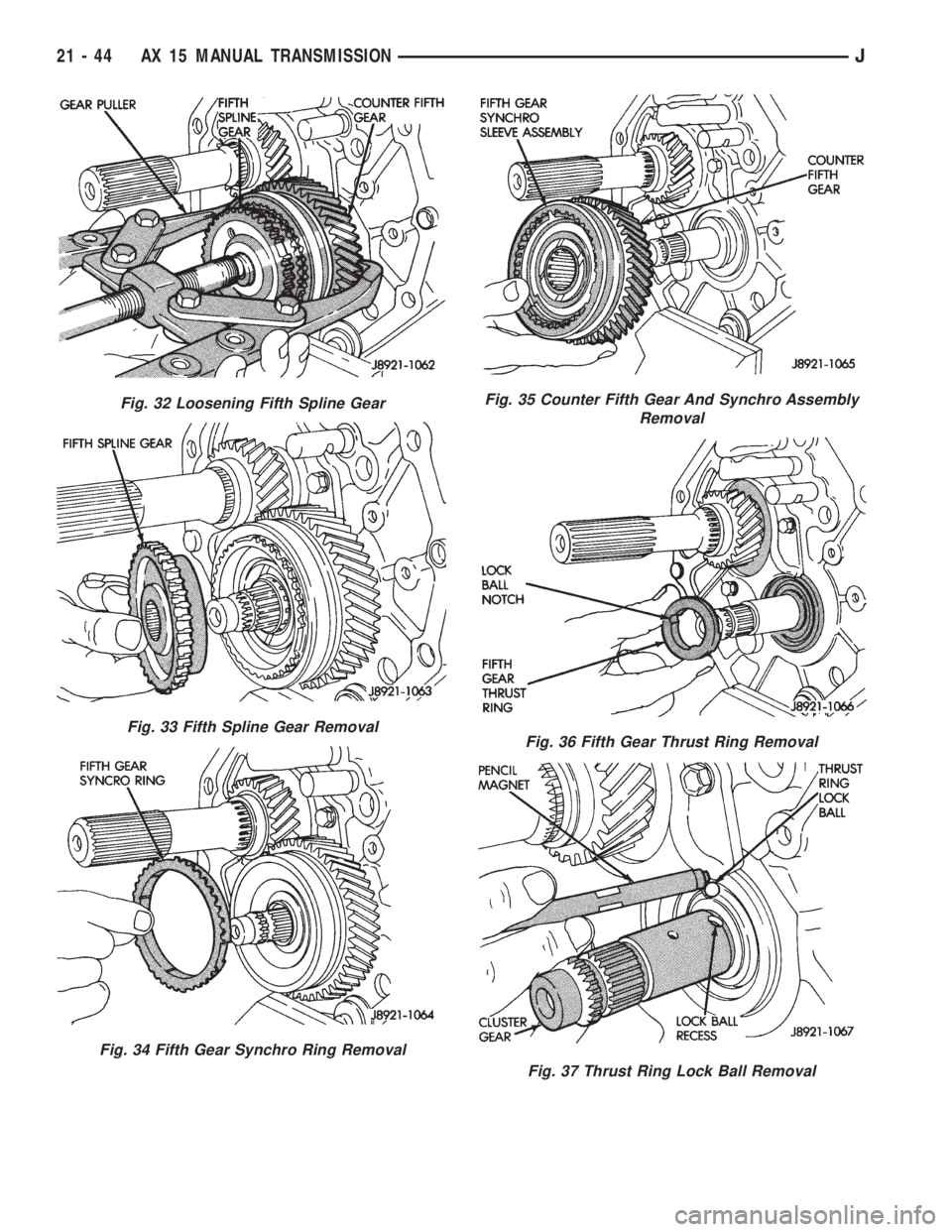
Fig. 32 Loosening Fifth Spline Gear
Fig. 33 Fifth Spline Gear Removal
Fig. 34 Fifth Gear Synchro Ring Removal
Fig. 35 Counter Fifth Gear And Synchro Assembly
Removal
Fig. 36 Fifth Gear Thrust Ring Removal
Fig. 37 Thrust Ring Lock Ball Removal
21 - 44 AX 15 MANUAL TRANSMISSIONJ
Page 1422 of 2198
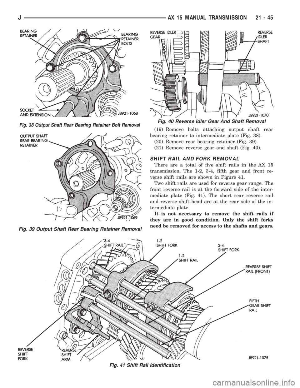
(19) Remove bolts attaching output shaft rear
bearing retainer to intermediate plate (Fig. 38).
(20) Remove rear bearing retainer (Fig. 39).
(21) Remove reverse gear and shaft (Fig. 40).
SHIFT RAIL AND FORK REMOVAL
There are a total of five shift rails in the AX 15
transmission. The 1-2, 3-4, fifth gear and front re-
verse shift rails are shown in Figure 41.
Two shift rails are used for reverse gear range. The
front reverse rail is at the forward side of the inter-
mediate plate (Fig. 41). The short rear reverse rail
and reverse shift head are at the rear side of the in-
termediate plate.
It is not necessary to remove the shift rails if
they are in good condition. Only the shift forks
need be removed for access to the shafts and gears.
Fig. 38 Output Shaft Rear Bearing Retainer Bolt Removal
Fig. 39 Output Shaft Rear Bearing Retainer Removal
Fig. 40 Reverse Idler Gear And Shaft Removal
Fig. 41 Shift Rail Identification
JAX 15 MANUAL TRANSMISSION 21 - 45
Page 1423 of 2198
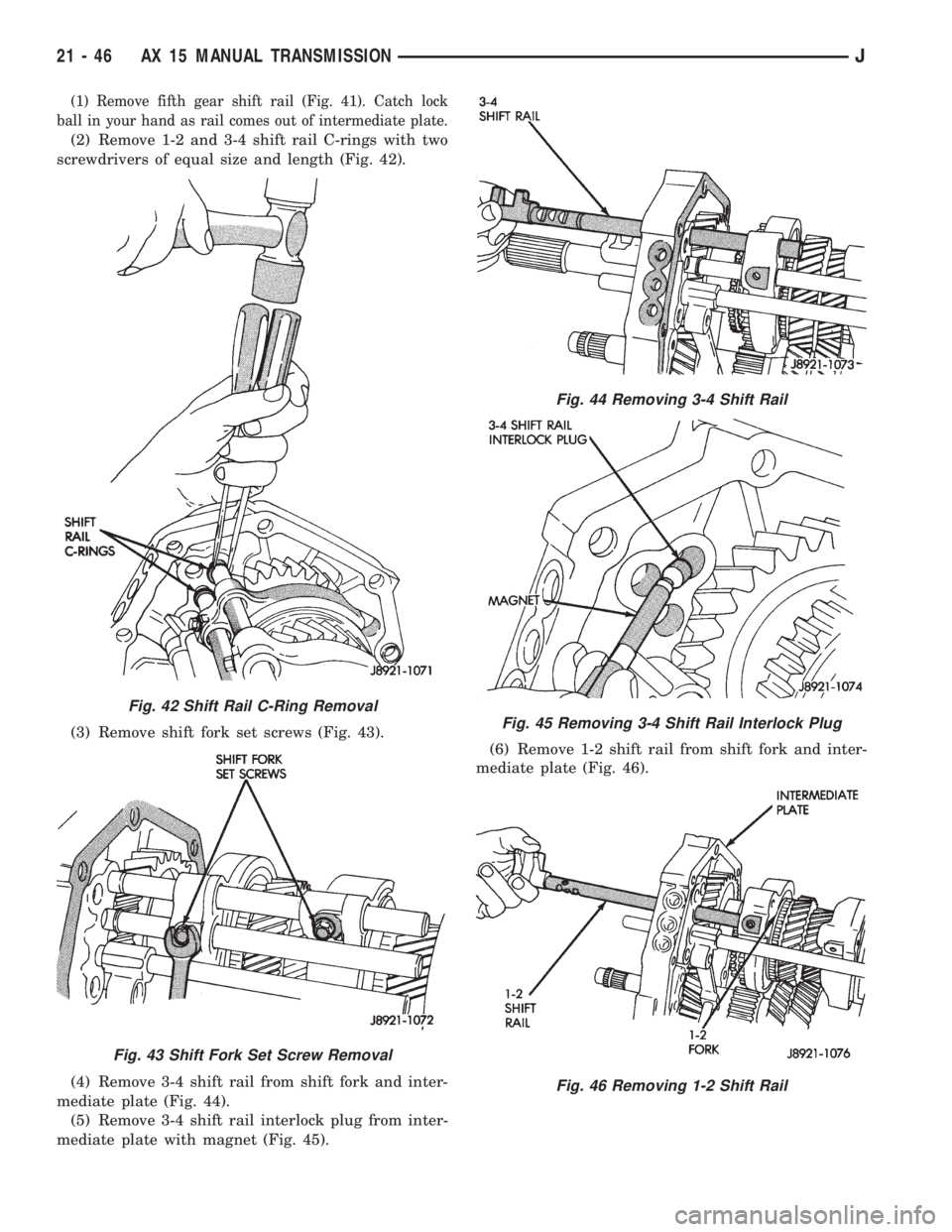
(1) Remove fifth gear shift rail (Fig. 41). Catch lock
ball in your hand as rail comes out of intermediate plate.
(2) Remove 1-2 and 3-4 shift rail C-rings with two
screwdrivers of equal size and length (Fig. 42).
(3) Remove shift fork set screws (Fig. 43).
(4) Remove 3-4 shift rail from shift fork and inter-
mediate plate (Fig. 44).
(5) Remove 3-4 shift rail interlock plug from inter-
mediate plate with magnet (Fig. 45).(6) Remove 1-2 shift rail from shift fork and inter-
mediate plate (Fig. 46).
Fig. 42 Shift Rail C-Ring Removal
Fig. 43 Shift Fork Set Screw Removal
Fig. 44 Removing 3-4 Shift Rail
Fig. 45 Removing 3-4 Shift Rail Interlock Plug
Fig. 46 Removing 1-2 Shift Rail
21 - 46 AX 15 MANUAL TRANSMISSIONJ
Page 1424 of 2198
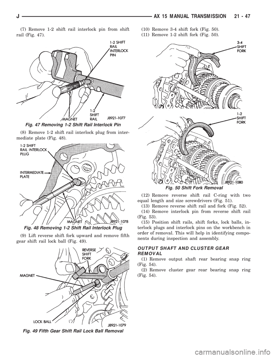
(7) Remove 1-2 shift rail interlock pin from shift
rail (Fig. 47).
(8) Remove 1-2 shift rail interlock plug from inter-
mediate plate (Fig. 48).
(9) Lift reverse shift fork upward and remove fifth
gear shift rail lock ball (Fig. 49).(10) Remove 3-4 shift fork (Fig. 50).
(11) Remove 1-2 shift fork (Fig. 50).
(12) Remove reverse shift rail C-ring with two
equal length and size screwdrivers (Fig. 51).
(13) Remove reverse shift rail and fork (Fig. 52).
(14) Remove interlock pin from reverse shift rail
(Fig. 53).
(15) Position shift rails, shift forks, lock balls, in-
terlock plugs and interlock pins on the workbench in
order of removal. This will help in identifying compo-
nents during inspection and assembly.
OUTPUT SHAFT AND CLUSTER GEAR
REMOVAL
(1) Remove output shaft rear bearing snap ring
(Fig. 54).
(2) Remove cluster gear rear bearing snap ring
(Fig. 54).
Fig. 47 Removing 1-2 Shift Rail Interlock Pin
Fig. 48 Removing 1-2 Shift Rail Interlock Plug
Fig. 49 Fifth Gear Shift Rail Lock Ball Removal
Fig. 50 Shift Fork Removal
JAX 15 MANUAL TRANSMISSION 21 - 47
Page 1425 of 2198
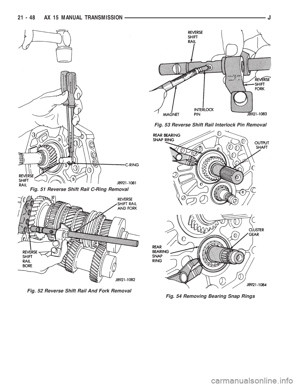
Fig. 51 Reverse Shift Rail C-Ring Removal
Fig. 52 Reverse Shift Rail And Fork Removal
Fig. 53 Reverse Shift Rail Interlock Pin Removal
Fig. 54 Removing Bearing Snap Rings
21 - 48 AX 15 MANUAL TRANSMISSIONJ
Page 1426 of 2198
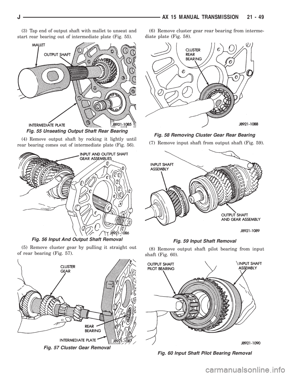
(3) Tap end of output shaft with mallet to unseat and
start rear bearing out of intermediate plate (Fig. 55).
(4) Remove output shaft by rocking it lightly until
rear bearing comes out of intermediate plate (Fig. 56).
(5) Remove cluster gear by pulling it straight out
of rear bearing (Fig. 57).(6) Remove cluster gear rear bearing from interme-
diate plate (Fig. 58).
(7) Remove input shaft from output shaft (Fig. 59).
(8) Remove output shaft pilot bearing from input
shaft (Fig. 60).
Fig. 55 Unseating Output Shaft Rear Bearing
Fig. 56 Input And Output Shaft Removal
Fig. 57 Cluster Gear Removal
Fig. 58 Removing Cluster Gear Rear Bearing
Fig. 59 Input Shaft Removal
Fig. 60 Input Shaft Pilot Bearing Removal
JAX 15 MANUAL TRANSMISSION 21 - 49
Page 1427 of 2198
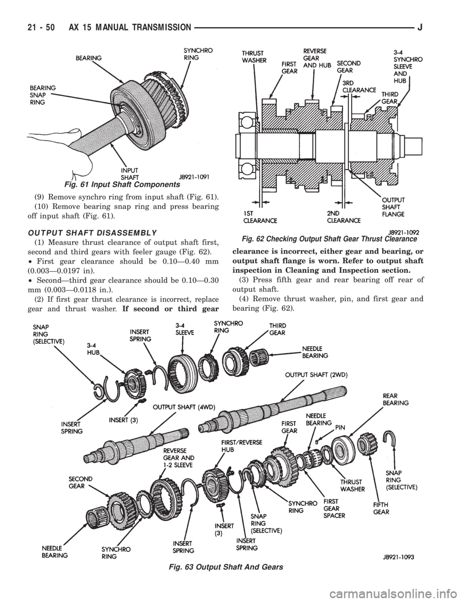
(9) Remove synchro ring from input shaft (Fig. 61).
(10) Remove bearing snap ring and press bearing
off input shaft (Fig. 61).
OUTPUT SHAFT DISASSEMBLY
(1) Measure thrust clearance of output shaft first,
second and third gears with feeler gauge (Fig. 62).
²First gear clearance should be 0.10Ð0.40 mm
(0.003Ð0.0197 in).
²SecondÐthird gear clearance should be 0.10Ð0.30
mm (0.003Ð0.0118 in.).
(2) If first gear thrust clearance is incorrect, replace
gear and thrust washer.If second or third gearclearance is incorrect, either gear and bearing, or
output shaft flange is worn. Refer to output shaft
inspection in Cleaning and Inspection section.
(3) Press fifth gear and rear bearing off rear of
output shaft.
(4) Remove thrust washer, pin, and first gear and
bearing (Fig. 62).
Fig. 61 Input Shaft Components
Fig. 62 Checking Output Shaft Gear Thrust Clearance
Fig. 63 Output Shaft And Gears
21 - 50 AX 15 MANUAL TRANSMISSIONJ
Page 1428 of 2198
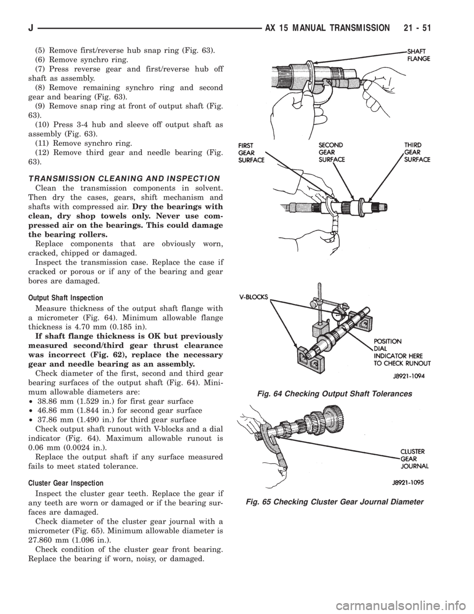
(5) Remove first/reverse hub snap ring (Fig. 63).
(6) Remove synchro ring.
(7) Press reverse gear and first/reverse hub off
shaft as assembly.
(8) Remove remaining synchro ring and second
gear and bearing (Fig. 63).
(9) Remove snap ring at front of output shaft (Fig.
63).
(10) Press 3-4 hub and sleeve off output shaft as
assembly (Fig. 63).
(11) Remove synchro ring.
(12) Remove third gear and needle bearing (Fig.
63).
TRANSMISSION CLEANING AND INSPECTION
Clean the transmission components in solvent.
Then dry the cases, gears, shift mechanism and
shafts with compressed air.Dry the bearings with
clean, dry shop towels only. Never use com-
pressed air on the bearings. This could damage
the bearing rollers.
Replace components that are obviously worn,
cracked, chipped or damaged.
Inspect the transmission case. Replace the case if
cracked or porous or if any of the bearing and gear
bores are damaged.
Output Shaft Inspection
Measure thickness of the output shaft flange with
a micrometer (Fig. 64). Minimum allowable flange
thickness is 4.70 mm (0.185 in).
If shaft flange thickness is OK but previously
measured second/third gear thrust clearance
was incorrect (Fig. 62), replace the necessary
gear and needle bearing as an assembly.
Check diameter of the first, second and third gear
bearing surfaces of the output shaft (Fig. 64). Mini-
mum allowable diameters are:
²38.86 mm (1.529 in.) for first gear surface
²46.86 mm (1.844 in.) for second gear surface
²37.86 mm (1.490 in.) for third gear surface
Check output shaft runout with V-blocks and a dial
indicator (Fig. 64). Maximum allowable runout is
0.06 mm (0.0024 in.).
Replace the output shaft if any surface measured
fails to meet stated tolerance.
Cluster Gear Inspection
Inspect the cluster gear teeth. Replace the gear if
any teeth are worn or damaged or if the bearing sur-
faces are damaged.
Check diameter of the cluster gear journal with a
micrometer (Fig. 65). Minimum allowable diameter is
27.860 mm (1.096 in.).
Check condition of the cluster gear front bearing.
Replace the bearing if worn, noisy, or damaged.
Fig. 64 Checking Output Shaft Tolerances
Fig. 65 Checking Cluster Gear Journal Diameter
JAX 15 MANUAL TRANSMISSION 21 - 51
Page 1429 of 2198
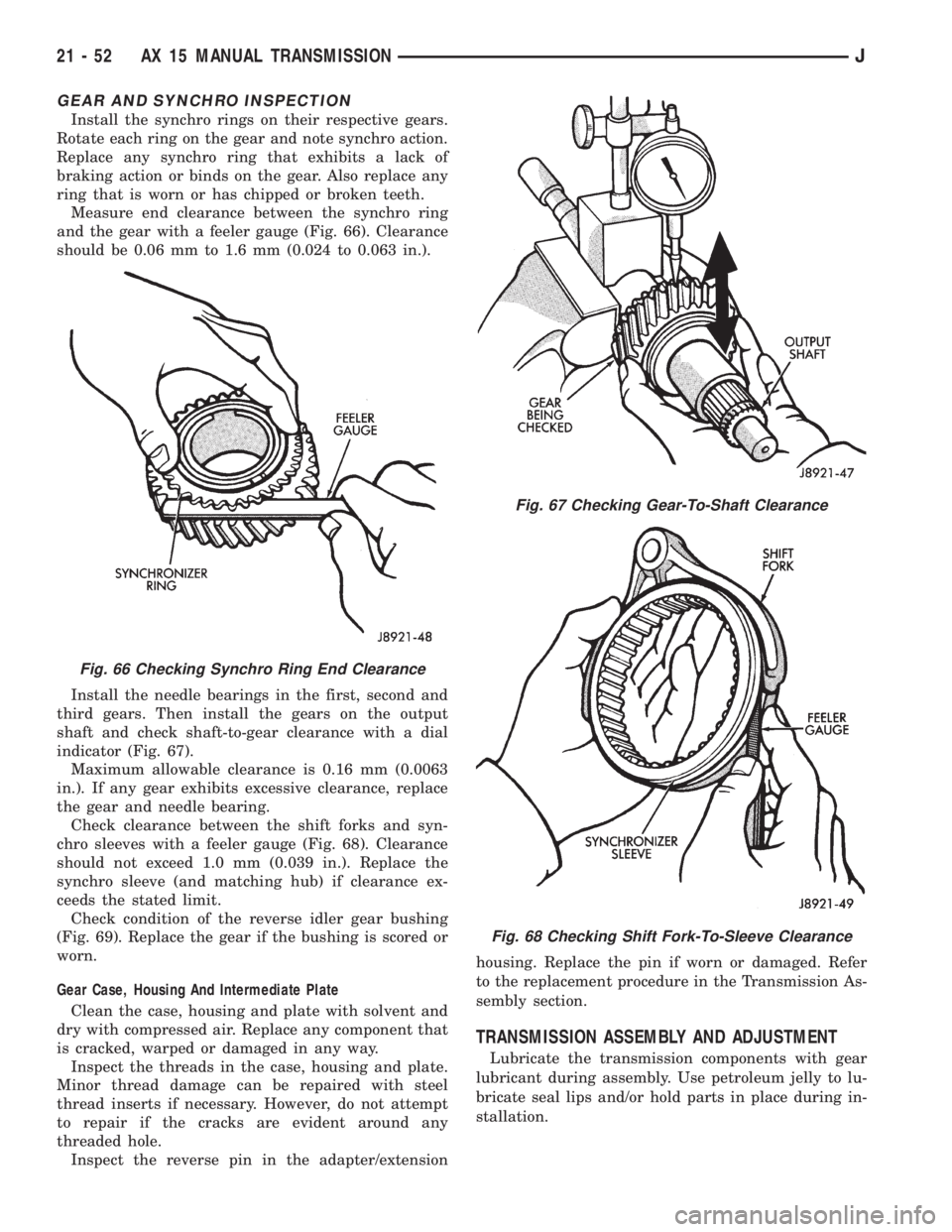
GEAR AND SYNCHRO INSPECTION
Install the synchro rings on their respective gears.
Rotate each ring on the gear and note synchro action.
Replace any synchro ring that exhibits a lack of
braking action or binds on the gear. Also replace any
ring that is worn or has chipped or broken teeth.
Measure end clearance between the synchro ring
and the gear with a feeler gauge (Fig. 66). Clearance
should be 0.06 mm to 1.6 mm (0.024 to 0.063 in.).
Install the needle bearings in the first, second and
third gears. Then install the gears on the output
shaft and check shaft-to-gear clearance with a dial
indicator (Fig. 67).
Maximum allowable clearance is 0.16 mm (0.0063
in.). If any gear exhibits excessive clearance, replace
the gear and needle bearing.
Check clearance between the shift forks and syn-
chro sleeves with a feeler gauge (Fig. 68). Clearance
should not exceed 1.0 mm (0.039 in.). Replace the
synchro sleeve (and matching hub) if clearance ex-
ceeds the stated limit.
Check condition of the reverse idler gear bushing
(Fig. 69). Replace the gear if the bushing is scored or
worn.
Gear Case, Housing And Intermediate Plate
Clean the case, housing and plate with solvent and
dry with compressed air. Replace any component that
is cracked, warped or damaged in any way.
Inspect the threads in the case, housing and plate.
Minor thread damage can be repaired with steel
thread inserts if necessary. However, do not attempt
to repair if the cracks are evident around any
threaded hole.
Inspect the reverse pin in the adapter/extensionhousing. Replace the pin if worn or damaged. Refer
to the replacement procedure in the Transmission As-
sembly section.
TRANSMISSION ASSEMBLY AND ADJUSTMENT
Lubricate the transmission components with gear
lubricant during assembly. Use petroleum jelly to lu-
bricate seal lips and/or hold parts in place during in-
stallation.
Fig. 66 Checking Synchro Ring End Clearance
Fig. 67 Checking Gear-To-Shaft Clearance
Fig. 68 Checking Shift Fork-To-Sleeve Clearance
21 - 52 AX 15 MANUAL TRANSMISSIONJ
Page 1430 of 2198
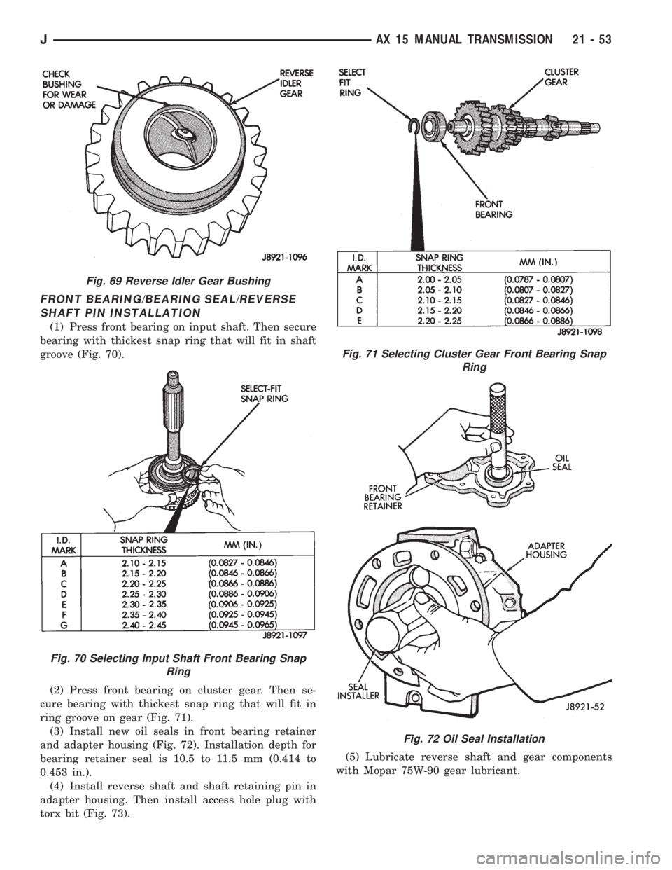
FRONT BEARING/BEARING SEAL/REVERSE
SHAFT PIN INSTALLATION
(1) Press front bearing on input shaft. Then secure
bearing with thickest snap ring that will fit in shaft
groove (Fig. 70).
(2) Press front bearing on cluster gear. Then se-
cure bearing with thickest snap ring that will fit in
ring groove on gear (Fig. 71).
(3) Install new oil seals in front bearing retainer
and adapter housing (Fig. 72). Installation depth for
bearing retainer seal is 10.5 to 11.5 mm (0.414 to
0.453 in.).
(4) Install reverse shaft and shaft retaining pin in
adapter housing. Then install access hole plug with
torx bit (Fig. 73).(5) Lubricate reverse shaft and gear components
with Mopar 75W-90 gear lubricant.
Fig. 69 Reverse Idler Gear Bushing
Fig. 70 Selecting Input Shaft Front Bearing Snap
Ring
Fig. 71 Selecting Cluster Gear Front Bearing Snap
Ring
Fig. 72 Oil Seal Installation
JAX 15 MANUAL TRANSMISSION 21 - 53