JEEP CHEROKEE 1995 Service Repair Manual
Manufacturer: JEEP, Model Year: 1995, Model line: CHEROKEE, Model: JEEP CHEROKEE 1995Pages: 2198, PDF Size: 82.83 MB
Page 1381 of 2198
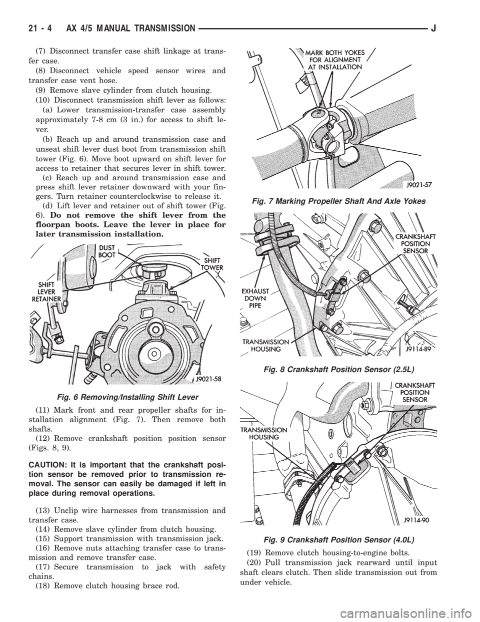
(7) Disconnect transfer case shift linkage at trans-
fer case.
(8) Disconnect vehicle speed sensor wires and
transfer case vent hose.
(9) Remove slave cylinder from clutch housing.
(10) Disconnect transmission shift lever as follows:
(a) Lower transmission-transfer case assembly
approximately 7-8 cm (3 in.) for access to shift le-
ver.
(b) Reach up and around transmission case and
unseat shift lever dust boot from transmission shift
tower (Fig. 6). Move boot upward on shift lever for
access to retainer that secures lever in shift tower.
(c) Reach up and around transmission case and
press shift lever retainer downward with your fin-
gers. Turn retainer counterclockwise to release it.
(d) Lift lever and retainer out of shift tower (Fig.
6).Do not remove the shift lever from the
floorpan boots. Leave the lever in place for
later transmission installation.
(11) Mark front and rear propeller shafts for in-
stallation alignment (Fig. 7). Then remove both
shafts.
(12) Remove crankshaft position position sensor
(Figs. 8, 9).
CAUTION: It is important that the crankshaft posi-
tion sensor be removed prior to transmission re-
moval. The sensor can easily be damaged if left in
place during removal operations.
(13) Unclip wire harnesses from transmission and
transfer case.
(14) Remove slave cylinder from clutch housing.
(15) Support transmission with transmission jack.
(16) Remove nuts attaching transfer case to trans-
mission and remove transfer case.
(17) Secure transmission to jack with safety
chains.
(18) Remove clutch housing brace rod.(19) Remove clutch housing-to-engine bolts.
(20) Pull transmission jack rearward until input
shaft clears clutch. Then slide transmission out from
under vehicle.
Fig. 6 Removing/Installing Shift Lever
Fig. 7 Marking Propeller Shaft And Axle Yokes
Fig. 8 Crankshaft Position Sensor (2.5L)
Fig. 9 Crankshaft Position Sensor (4.0L)
21 - 4 AX 4/5 MANUAL TRANSMISSIONJ
Page 1382 of 2198
(21) Remove clutch release bearing, release fork
and retainer clip.
(22) Remove clutch housing from transmission.
TRANSMISSION INSTALLATION
(1) Install clutch housing on transmission. Tighten
housing bolts to 37 Nzm (27 ft. lbs.) torque.
(2) Lubricate contact surfaces of release fork pivot
ball stud and release fork with high temp grease.
Then install release bearing, fork and retainer clip.
(3) Mount transmission on transmission jack.
(4) Lightly lubricate pilot bearing and transmis-
sion input shaft splines with Mopar high temp
grease.
(5) Align transmission input shaft, release bearing,
and clutch disc splines. Then slide transmission into
place.
(6) Install and tighten clutch housing-to-engine
bolts to 38 Nzm (28 ft. lbs.) torque.Be sure the
housing is properly seated on engine block be-
fore tightening bolts.
(7) Lower transmission approximately 7-8 cm (3
in.) for access to shift tower. Be sure transmission is
in first or third gear.
(8) Reach up and around transmission and insert
shift lever in shift tower. Press lever retainer down-
ward and turn it clockwise to lock it in place. Then
install lever dust boot on shift tower.
(9) Install slave cylinder in clutch housing.
(10) Align and install transfer case on and trans-
mission. Tighten transfer case-to-transmission nuts
to 35 Nzm (26 ft. lbs.) torque.
(11) Connect transfer case vent hose and shift link-
age. Check and adjust linkage if necessary.
(12) Connect transfer case vent hose.
(13) Secure wire harnesses in clips/tie straps on
transmission and transfer case.
(14) Connect backup light switch wires.
(15) Connect vehicle speed sensor wires.
(16) Install and connect crankshaft position sensor.
(17) Install rear crossmember (Fig. 5). On XJ,
tighten crossmember-to-frame bolts to 41 Nzm (31 ft.
lbs.) torque. Then tighten transmission-to-rear sup-
port bolts/nuts to 45 Nzm (33 ft. lbs.) torque. On YJ,
tighten bolts/nuts to indicated torque (Fig. 5).
(18) Remove jack stand.
(19) Align and install front/rear propeller shafts.
Tighten shaft U-joint clamp bolts to 19 Nzm (170 in.
lbs.) torque.
(20) Install skid plate, if equipped. Tighten bolts to
42 Nzm (31 ft. lbs.) torque. Tighten stud nuts to 17
Nzm (150 in. lbs.) torque.
(21) Top off transmission and transfer case lubri-
cant levels.
(22) Lower vehicle.
TRANSMISSION DISASSEMBLY AND OVERHAUL
ADAPTER HOUSING AND FRONT BEARING
RETAINER REMOVAL
(1) Drain transmission lubricant.
(2) Remove release bearing and lever.
(3) Remove clutch housing bolts and remove hous-
ing.
(4) On 2-wheel drive models, remove vehicle speed
sensor, speedometer adapter and speedometer driven
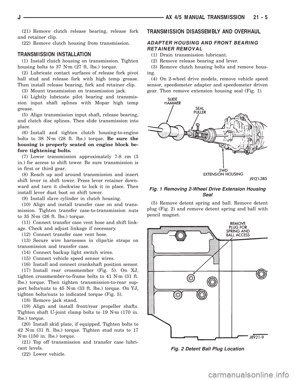
gear. Then remove extension housing seal (Fig. 1).
(5) Remove detent spring and ball. Remove detent
plug (Fig. 2) and remove detent spring and ball with
pencil magnet.
Fig. 1 Removing 2-Wheel Drive Extension Housing
Seal
Fig. 2 Detent Ball Plug Location
JAX 4/5 MANUAL TRANSMISSION 21 - 5
Page 1383 of 2198
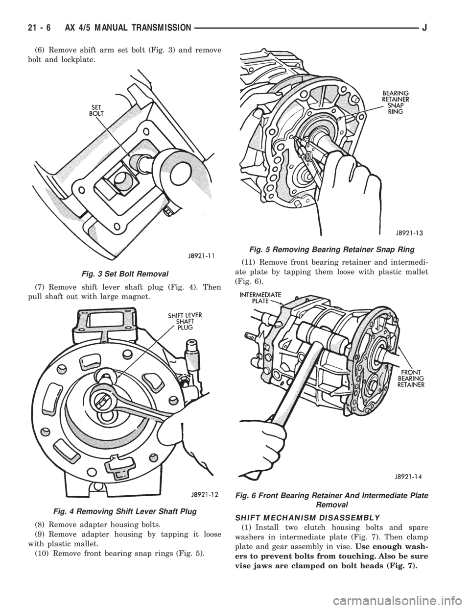
(6) Remove shift arm set bolt (Fig. 3) and remove
bolt and lockplate.
(7) Remove shift lever shaft plug (Fig. 4). Then
pull shaft out with large magnet.
(8) Remove adapter housing bolts.
(9) Remove adapter housing by tapping it loose
with plastic mallet.
(10) Remove front bearing snap rings (Fig. 5).(11) Remove front bearing retainer and intermedi-
ate plate by tapping them loose with plastic mallet
(Fig. 6).
SHIFT MECHANISM DISASSEMBLY
(1) Install two clutch housing bolts and spare
washers in intermediate plate (Fig. 7). Then clamp
plate and gear assembly in vise.Use enough wash-
ers to prevent bolts from touching. Also be sure
vise jaws are clamped on bolt heads (Fig. 7).
Fig. 3 Set Bolt Removal
Fig. 4 Removing Shift Lever Shaft Plug
Fig. 5 Removing Bearing Retainer Snap Ring
Fig. 6 Front Bearing Retainer And Intermediate Plate
Removal
21 - 6 AX 4/5 MANUAL TRANSMISSIONJ
Page 1384 of 2198
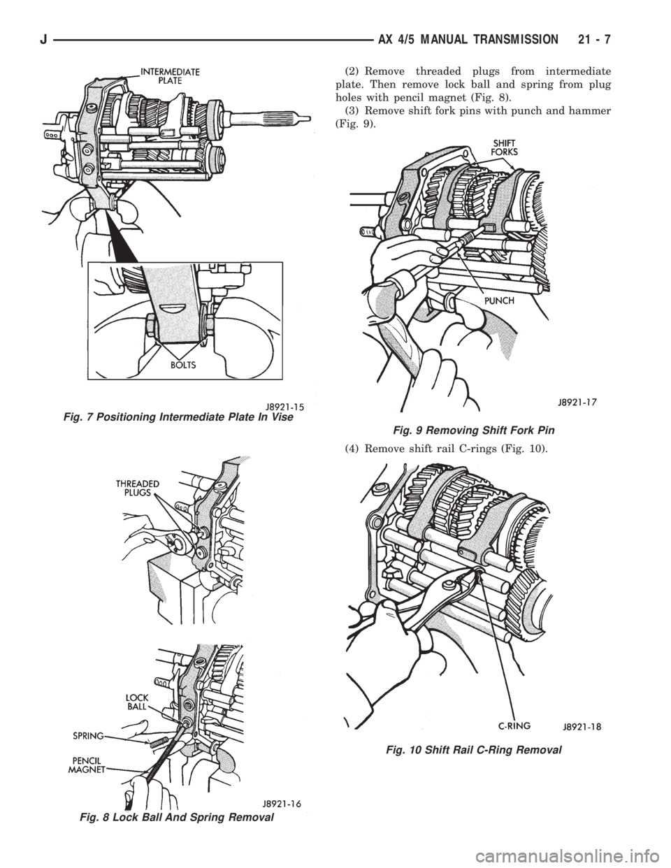
(2) Remove threaded plugs from intermediate
plate. Then remove lock ball and spring from plug
holes with pencil magnet (Fig. 8).
(3) Remove shift fork pins with punch and hammer
(Fig. 9).
(4) Remove shift rail C-rings (Fig. 10).
Fig. 7 Positioning Intermediate Plate In Vise
Fig. 8 Lock Ball And Spring Removal
Fig. 9 Removing Shift Fork Pin
Fig. 10 Shift Rail C-Ring Removal
JAX 4/5 MANUAL TRANSMISSION 21 - 7
Page 1385 of 2198
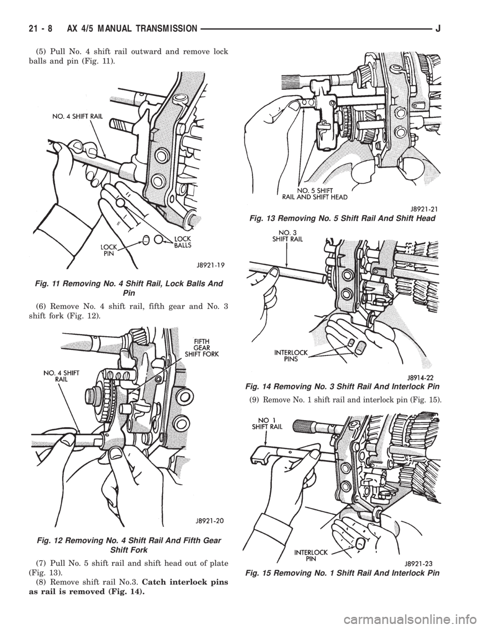
(5) Pull No. 4 shift rail outward and remove lock
balls and pin (Fig. 11).
(6) Remove No. 4 shift rail, fifth gear and No. 3
shift fork (Fig. 12).
(7) Pull No. 5 shift rail and shift head out of plate
(Fig. 13).
(8) Remove shift rail No.3.Catch interlock pins
as rail is removed (Fig. 14).
(9) Remove No. 1 shift rail and interlock pin (Fig. 15).
Fig. 11 Removing No. 4 Shift Rail, Lock Balls And
Pin
Fig. 12 Removing No. 4 Shift Rail And Fifth Gear
Shift Fork
Fig. 13 Removing No. 5 Shift Rail And Shift Head
Fig. 14 Removing No. 3 Shift Rail And Interlock Pin
Fig. 15 Removing No. 1 Shift Rail And Interlock Pin
21 - 8 AX 4/5 MANUAL TRANSMISSIONJ
Page 1386 of 2198
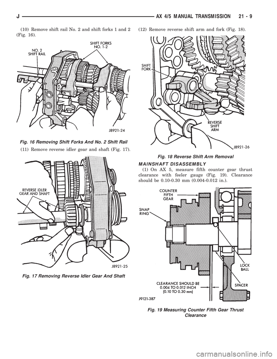
(10) Remove shift rail No. 2 and shift forks 1 and 2
(Fig. 16).
(11) Remove reverse idler gear and shaft (Fig. 17).(12) Remove reverse shift arm and fork (Fig. 18).
MAINSHAFT DISASSEMBLY
(1) On AX 5, measure fifth counter gear thrust
clearance with feeler gauge (Fig. 19). Clearance
should be 0.10-0.30 mm (0.004-0.012 in.).
Fig. 16 Removing Shift Forks And No. 2 Shift Rail
Fig. 17 Removing Reverse Idler Gear And Shaft
Fig. 18 Reverse Shift Arm Removal
Fig. 19 Measuring Counter Fifth Gear Thrust
Clearance
JAX 4/5 MANUAL TRANSMISSION 21 - 9
Page 1387 of 2198
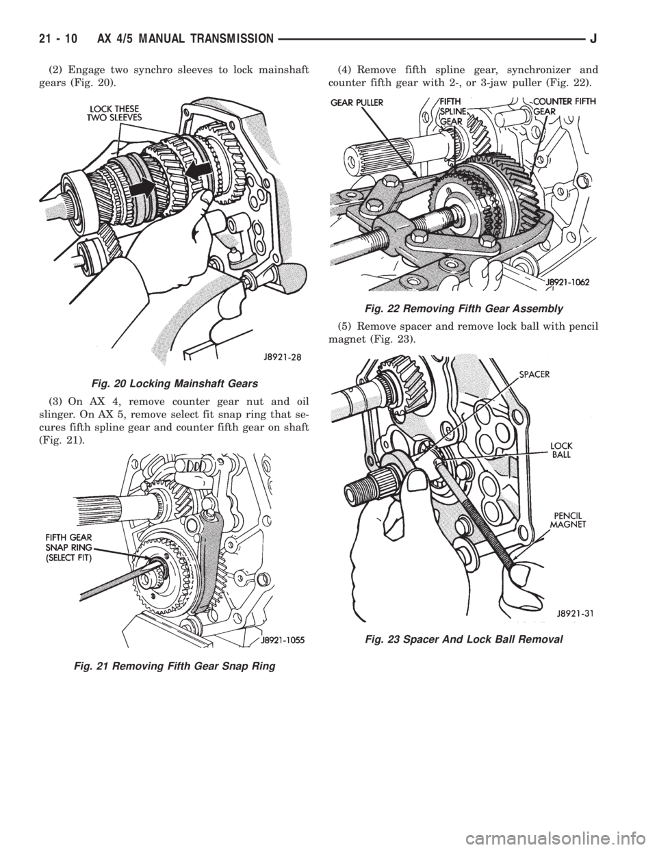
(2) Engage two synchro sleeves to lock mainshaft
gears (Fig. 20).
(3) On AX 4, remove counter gear nut and oil
slinger. On AX 5, remove select fit snap ring that se-
cures fifth spline gear and counter fifth gear on shaft
(Fig. 21).(4) Remove fifth spline gear, synchronizer and
counter fifth gear with 2-, or 3-jaw puller (Fig. 22).
(5) Remove spacer and remove lock ball with pencil
magnet (Fig. 23).
Fig. 20 Locking Mainshaft Gears
Fig. 21 Removing Fifth Gear Snap Ring
Fig. 22 Removing Fifth Gear Assembly
Fig. 23 Spacer And Lock Ball Removal
21 - 10 AX 4/5 MANUAL TRANSMISSIONJ
Page 1388 of 2198
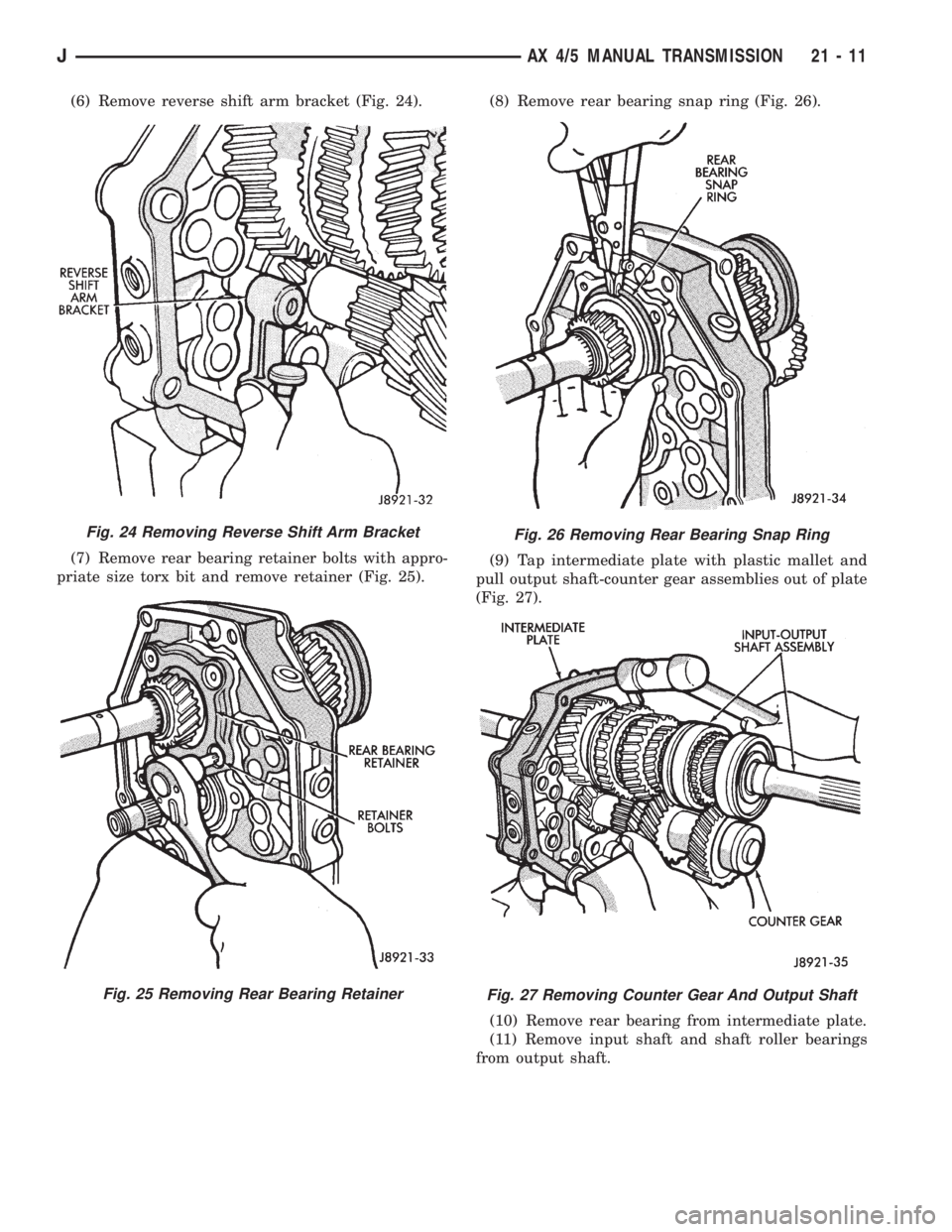
(6) Remove reverse shift arm bracket (Fig. 24).
(7) Remove rear bearing retainer bolts with appro-
priate size torx bit and remove retainer (Fig. 25).(8) Remove rear bearing snap ring (Fig. 26).
(9) Tap intermediate plate with plastic mallet and
pull output shaft-counter gear assemblies out of plate
(Fig. 27).
(10) Remove rear bearing from intermediate plate.
(11) Remove input shaft and shaft roller bearings
from output shaft.
Fig. 24 Removing Reverse Shift Arm Bracket
Fig. 25 Removing Rear Bearing Retainer
Fig. 26 Removing Rear Bearing Snap Ring
Fig. 27 Removing Counter Gear And Output Shaft
JAX 4/5 MANUAL TRANSMISSION 21 - 11
Page 1389 of 2198
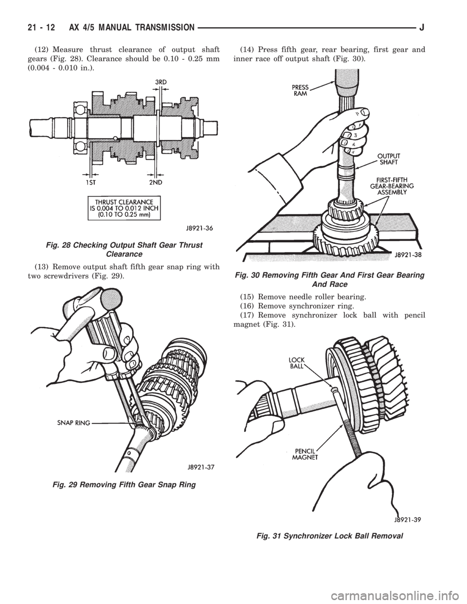
(12) Measure thrust clearance of output shaft
gears (Fig. 28). Clearance should be 0.10 - 0.25 mm
(0.004 - 0.010 in.).
(13) Remove output shaft fifth gear snap ring with
two screwdrivers (Fig. 29).(14) Press fifth gear, rear bearing, first gear and
inner race off output shaft (Fig. 30).
(15) Remove needle roller bearing.
(16) Remove synchronizer ring.
(17) Remove synchronizer lock ball with pencil
magnet (Fig. 31).
Fig. 28 Checking Output Shaft Gear Thrust
Clearance
Fig. 29 Removing Fifth Gear Snap Ring
Fig. 30 Removing Fifth Gear And First Gear Bearing
And Race
Fig. 31 Synchronizer Lock Ball Removal
21 - 12 AX 4/5 MANUAL TRANSMISSIONJ
Page 1390 of 2198
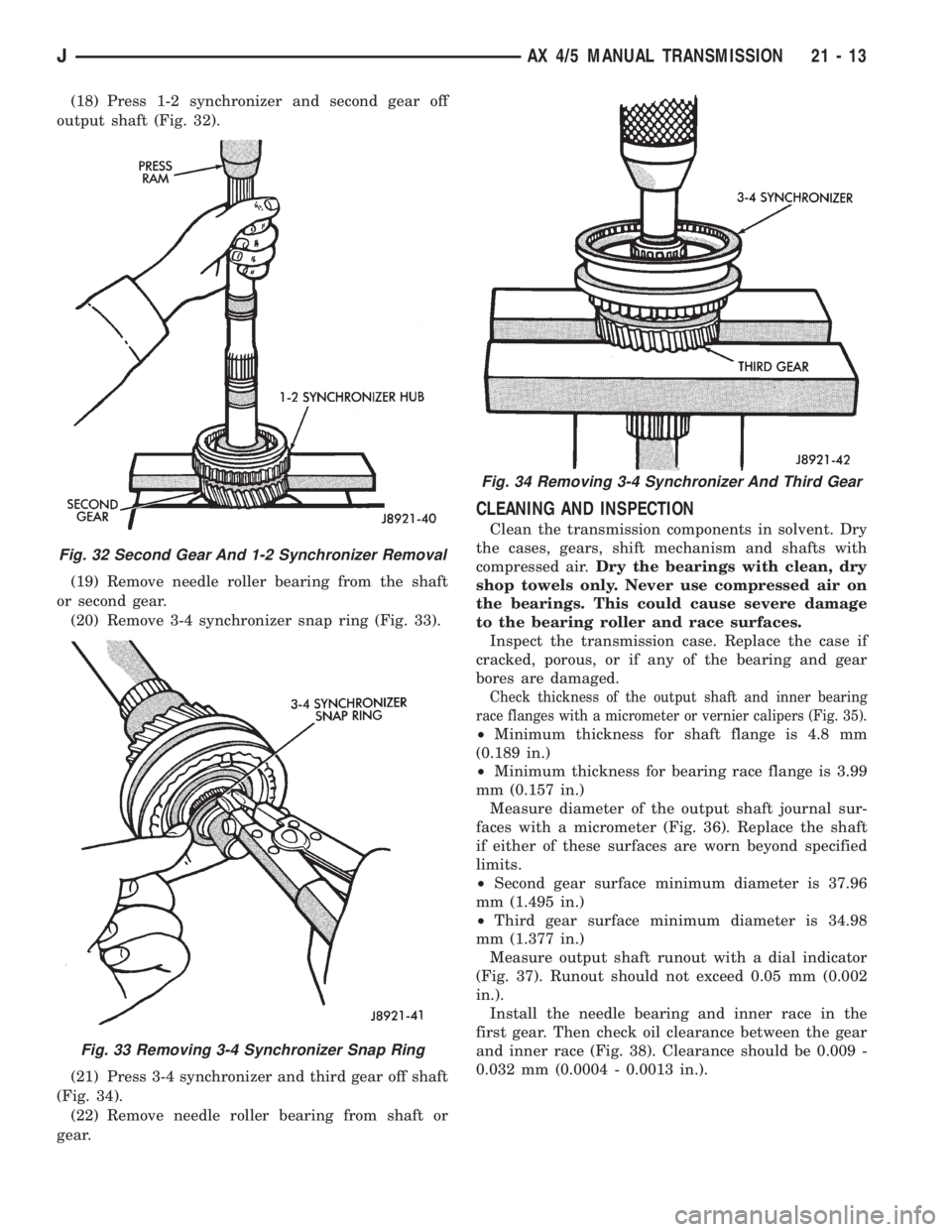
(18) Press 1-2 synchronizer and second gear off
output shaft (Fig. 32).
(19) Remove needle roller bearing from the shaft
or second gear.
(20) Remove 3-4 synchronizer snap ring (Fig. 33).
(21) Press 3-4 synchronizer and third gear off shaft
(Fig. 34).
(22) Remove needle roller bearing from shaft or
gear.
CLEANING AND INSPECTION
Clean the transmission components in solvent. Dry
the cases, gears, shift mechanism and shafts with
compressed air.Dry the bearings with clean, dry
shop towels only. Never use compressed air on
the bearings. This could cause severe damage
to the bearing roller and race surfaces.
Inspect the transmission case. Replace the case if
cracked, porous, or if any of the bearing and gear
bores are damaged.
Check thickness of the output shaft and inner bearing
race flanges with a micrometer or vernier calipers (Fig. 35).
²Minimum thickness for shaft flange is 4.8 mm
(0.189 in.)
²Minimum thickness for bearing race flange is 3.99
mm (0.157 in.)
Measure diameter of the output shaft journal sur-
faces with a micrometer (Fig. 36). Replace the shaft
if either of these surfaces are worn beyond specified
limits.
²Second gear surface minimum diameter is 37.96
mm (1.495 in.)
²Third gear surface minimum diameter is 34.98
mm (1.377 in.)
Measure output shaft runout with a dial indicator
(Fig. 37). Runout should not exceed 0.05 mm (0.002
in.).
Install the needle bearing and inner race in the
first gear. Then check oil clearance between the gear
and inner race (Fig. 38). Clearance should be 0.009 -
0.032 mm (0.0004 - 0.0013 in.).
Fig. 32 Second Gear And 1-2 Synchronizer Removal
Fig. 33 Removing 3-4 Synchronizer Snap Ring
Fig. 34 Removing 3-4 Synchronizer And Third Gear
JAX 4/5 MANUAL TRANSMISSION 21 - 13