ad blue JEEP CHEROKEE 1995 Service Repair Manual
[x] Cancel search | Manufacturer: JEEP, Model Year: 1995, Model line: CHEROKEE, Model: JEEP CHEROKEE 1995Pages: 2198, PDF Size: 82.83 MB
Page 409 of 2198
SPEED CONTROL SWITCH
WARNING: ON VEHICLES EQUIPPED WITH AN AIR-
BAG, REFER TO GROUP 8M - RESTRAINT SYS-
TEMS BEFORE ATTEMPTING STEERING WHEEL
COMPONENT DIAGNOSIS OR SERVICE. FAILURE
TO TAKE PROPER PRECAUTIONS COULD RESULT
IN ACCIDENTAL AIRBAG DEPLOYMENT AND POS-
SIBLE PERSONAL INJURY.
(1) Disconnect battery negative cable. Remove
speed control switch from steering wheel.
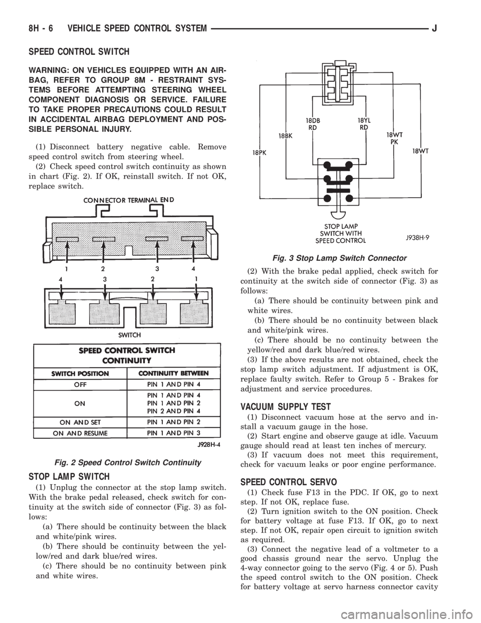
(2) Check speed control switch continuity as shown
in chart (Fig. 2). If OK, reinstall switch. If not OK,
replace switch.
STOP LAMP SWITCH
(1) Unplug the connector at the stop lamp switch.
With the brake pedal released, check switch for con-
tinuity at the switch side of connector (Fig. 3) as fol-
lows:
(a) There should be continuity between the black
and white/pink wires.
(b) There should be continuity between the yel-
low/red and dark blue/red wires.
(c) There should be no continuity between pink
and white wires.(2) With the brake pedal applied, check switch for
continuity at the switch side of connector (Fig. 3) as
follows:
(a) There should be continuity between pink and
white wires.
(b) There should be no continuity between black
and white/pink wires.
(c) There should be no continuity between the
yellow/red and dark blue/red wires.
(3) If the above results are not obtained, check the
stop lamp switch adjustment. If adjustment is OK,
replace faulty switch. Refer to Group 5 - Brakes for
adjustment and service procedures.
VACUUM SUPPLY TEST
(1) Disconnect vacuum hose at the servo and in-
stall a vacuum gauge in the hose.
(2) Start engine and observe gauge at idle. Vacuum
gauge should read at least ten inches of mercury.
(3) If vacuum does not meet this requirement,
check for vacuum leaks or poor engine performance.
SPEED CONTROL SERVO
(1) Check fuse F13 in the PDC. If OK, go to next
step. If not OK, replace fuse.
(2) Turn ignition switch to the ON position. Check
for battery voltage at fuse F13. If OK, go to next
step. If not OK, repair open circuit to ignition switch
as required.
(3) Connect the negative lead of a voltmeter to a
good chassis ground near the servo. Unplug the
4-way connector going to the servo (Fig. 4 or 5). Push
the speed control switch to the ON position. Check
for battery voltage at servo harness connector cavity
Fig. 2 Speed Control Switch Continuity
Fig. 3 Stop Lamp Switch Connector
8H - 6 VEHICLE SPEED CONTROL SYSTEMJ
Page 417 of 2198
lamps and repair circuits or replace bulbs as re-
quired. If system still does not function properly, pro-
ceed as follows.
(1) Locate fuseblock module under driver's side of
instrument panel. Remove and inspect fuse 4. If OK,
go to next step. If not OK, replace fuse as required.
(2) Replace turn signal flasher (light blue can in
fuseblock module) with a known good unit. Test op-
eration. If OK, replace faulty turn signal flasher. If
not OK, remove test flasher and go to next step.
(3) Turn ignition switch to ACCESSORY position.
Check for battery voltage at flasher cavity on left
(closest to hazard flasher). If OK, go to next step. If
not OK, repair circuit to fuse 4 as required.
(4) Turn ignition switch to OFF position. See Turn
Signal/Hazard Warning Switch Remove/Install to lo-
cate steering column connector. Unplug connector.
(5) Turn ignition switch to ACCESSORY position.
Check for battery voltage at connector terminal L. If
OK, replace turn signal/hazard warning switch. If not
OK, repair circuit between turn signal flasher and
steering column connector.
HAZARD WARNING SYSTEM - YJ
(1) Locate Power Distribution Center (PDC) near
battery tray in engine compartment. Remove and in-
spect fuse F5. If OK, go to next step. If not OK,
replace fuse as required.(2) Replace hazard warning flasher (metal can in
fuseblock module) with a known good unit. Test op-
eration. If OK, replace faulty hazard warning flasher.
If not OK, remove test flasher and go to next step.
(3) Check for battery voltage at flasher cavity on
left (closest to hazard flasher). If OK, go to next step.
If not OK, repair circuit to fuse F5 in PDC as re-
quired.
(4) See Turn Signal/Hazard Warning Switch Re-
move/Install to locate steering column connector. Un-
plug connector.
(5) Check for battery voltage at connector terminal
K. If OK, replace turn signal/hazard warning switch.
If not OK, repair circuit between hazard warning
flasher and steering column connector.
MULTI-FUNCTION SWITCH - XJ
(1) Access multi-function switch connector and re-
move. See service procedures for Multi-Function
Switch, in this group.
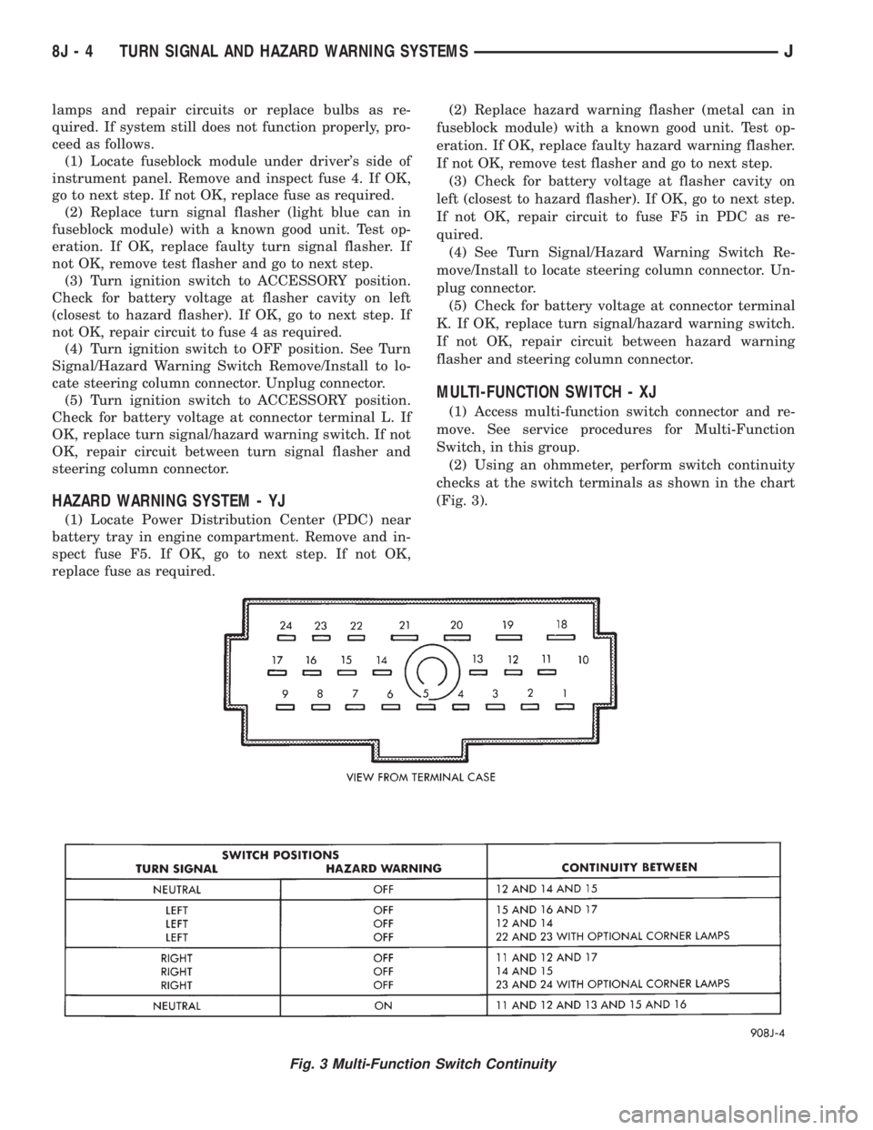
(2) Using an ohmmeter, perform switch continuity
checks at the switch terminals as shown in the chart
(Fig. 3).
Fig. 3 Multi-Function Switch Continuity
8J - 4 TURN SIGNAL AND HAZARD WARNING SYSTEMSJ
Page 519 of 2198
DIAGNOSIS
BUZZER MODULE
(1) Check fuses (15 and 17 - XJ, 3 and 9 - YJ) in
the fuseblock module. If fuses are OK, go to next
step. If not OK, replace fuses as required.
(2) Check for battery voltage at fuse (15 - XJ, 3 -
YJ) in fuseblock module. If OK, go to next step. If not
OK, repair feed circuit from power distribution center
as required.
(3) Turn ignition switch to ON position. Check for
battery voltage at fuse (17 - XJ, 9 - YJ) in the fuse-
block module. If OK, go to next step. If not OK, re-
pair feed from ignition switch as required.
(4) Turn ignition switch to OFF position. Replace
buzzer module with a known good unit and test op-
eration. If not OK, remove buzzer module and go to
next step.
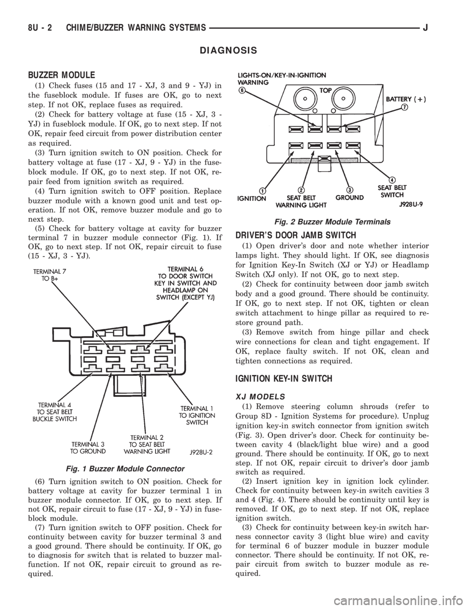
(5) Check for battery voltage at cavity for buzzer
terminal 7 in buzzer module connector (Fig. 1). If
OK, go to next step. If not OK, repair circuit to fuse
(15 - XJ, 3 - YJ).
(6) Turn ignition switch to ON position. Check for
battery voltage at cavity for buzzer terminal 1 in
buzzer module connector. If OK, go to next step. If
not OK, repair circuit to fuse (17 - XJ, 9 - YJ) in fuse-
block module.
(7) Turn ignition switch to OFF position. Check for
continuity between cavity for buzzer terminal 3 and
a good ground. There should be continuity. If OK, go
to diagnosis for switch that is related to buzzer mal-
function. If not OK, repair circuit to ground as re-
quired.
DRIVER'S DOOR JAMB SWITCH
(1) Open driver's door and note whether interior
lamps light. They should light. If OK, see diagnosis
for Ignition Key-In Switch (XJ or YJ) or Headlamp
Switch (XJ only). If not OK, go to next step.
(2) Check for continuity between door jamb switch
body and a good ground. There should be continuity.
If OK, go to next step. If not OK, tighten or clean
switch attachment to hinge pillar as required to re-
store ground path.
(3) Remove switch from hinge pillar and check
wire connections for clean and tight engagement. If
OK, replace faulty switch. If not OK, clean and
tighten connections as required.
IGNITION KEY-IN SWITCH
XJ MODELS
(1) Remove steering column shrouds (refer to
Group 8D - Ignition Systems for procedure). Unplug
ignition key-in switch connector from ignition switch
(Fig. 3). Open driver's door. Check for continuity be-
tween cavity 4 (black/light blue wire) and a good
ground. There should be continuity. If OK, go to next
step. If not OK, repair circuit to driver's door jamb
switch as required.
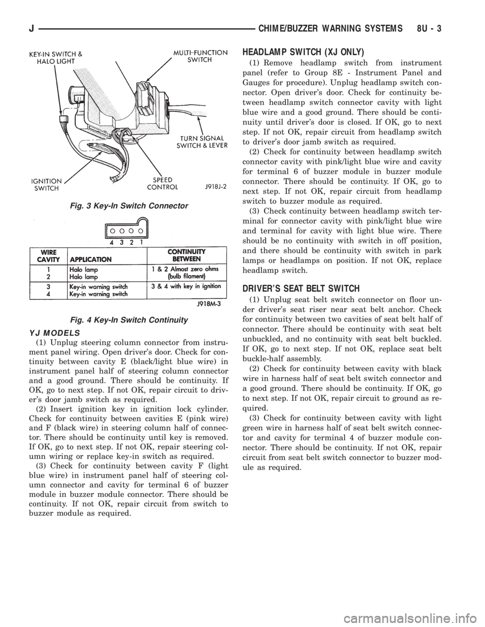
(2) Insert ignition key in ignition lock cylinder.
Check for continuity between key-in switch cavities 3
and 4 (Fig. 4). There should be continuity until key is
removed. If OK, go to next step. If not OK, replace
ignition switch.
(3) Check for continuity between key-in switch har-
ness connector cavity 3 (light blue wire) and cavity
for terminal 6 of buzzer module in buzzer module
connector. There should be continuity. If not OK, re-
pair circuit from switch to buzzer module as re-
quired.
Fig. 1 Buzzer Module Connector
Fig. 2 Buzzer Module Terminals
8U - 2 CHIME/BUZZER WARNING SYSTEMSJ
Page 520 of 2198
YJ MODELS
(1) Unplug steering column connector from instru-
ment panel wiring. Open driver's door. Check for con-
tinuity between cavity E (black/light blue wire) in
instrument panel half of steering column connector
and a good ground. There should be continuity. If
OK, go to next step. If not OK, repair circuit to driv-
er's door jamb switch as required.
(2) Insert ignition key in ignition lock cylinder.
Check for continuity between cavities E (pink wire)
and F (black wire) in steering column half of connec-
tor. There should be continuity until key is removed.
If OK, go to next step. If not OK, repair steering col-
umn wiring or replace key-in switch as required.
(3) Check for continuity between cavity F (light
blue wire) in instrument panel half of steering col-
umn connector and cavity for terminal 6 of buzzer
module in buzzer module connector. There should be
continuity. If not OK, repair circuit from switch to
buzzer module as required.
HEADLAMP SWITCH (XJ ONLY)
(1) Remove headlamp switch from instrument
panel (refer to Group 8E - Instrument Panel and
Gauges for procedure). Unplug headlamp switch con-
nector. Open driver's door. Check for continuity be-
tween headlamp switch connector cavity with light
blue wire and a good ground. There should be conti-
nuity until driver's door is closed. If OK, go to next
step. If not OK, repair circuit from headlamp switch
to driver's door jamb switch as required.
(2) Check for continuity between headlamp switch
connector cavity with pink/light blue wire and cavity
for terminal 6 of buzzer module in buzzer module
connector. There should be continuity. If OK, go to
next step. If not OK, repair circuit from headlamp
switch to buzzer module as required.
(3) Check continuity between headlamp switch ter-
minal for connector cavity with pink/light blue wire
and terminal for cavity with light blue wire. There
should be no continuity with switch in off position,
and there should be continuity with switch in park
lamps or headlamps on position. If not OK, replace
headlamp switch.
DRIVER'S SEAT BELT SWITCH
(1) Unplug seat belt switch connector on floor un-
der driver's seat riser near seat belt anchor. Check
for continuity between two cavities of seat belt half of
connector. There should be continuity with seat belt
unbuckled, and no continuity with seat belt buckled.
If OK, go to next step. If not OK, replace seat belt
buckle-half assembly.
(2) Check for continuity between cavity with black
wire in harness half of seat belt switch connector and
a good ground. There should be continuity. If OK, go
to next step. If not OK, repair circuit to ground as re-
quired.
(3) Check for continuity between cavity with light
green wire in harness half of seat belt switch connec-
tor and cavity for terminal 4 of buzzer module con-
nector. There should be continuity. If not OK, repair
circuit from seat belt switch connector to buzzer mod-
ule as required.
Fig. 3 Key-In Switch Connector
Fig. 4 Key-In Switch Continuity
JCHIME/BUZZER WARNING SYSTEMS 8U - 3
Page 1810 of 2198
TRAILER HITCH
TRAILER HITCHÐXJ
CLASS III HITCH
A class III weight-distributing/equalizer type hitch
can be used to tow a trailer:
²Having a maximum gross weight of 5,000 lbs/2250
kg.
²Having a maximum tongue weight of 750 lbs/332
kg).
The following vehicle basic equipment is required
for class III trailer towing:
²P205/75R15 or larger tires.
²Full size spare tire.
²Trailer sway control.
²Trailer tow wire harness and connector.
²Heavy duty turn signal flasher element.
²Heavy duty axle (with synthetic lubricant).
²Heavy duty cooling system.
²Heavy duty generator/battery.
²Auxiliary automatic transmission fluid cooler.
²I-6, 4.0L engine.
Wide-angle type door mirrors are recommended but
not required.
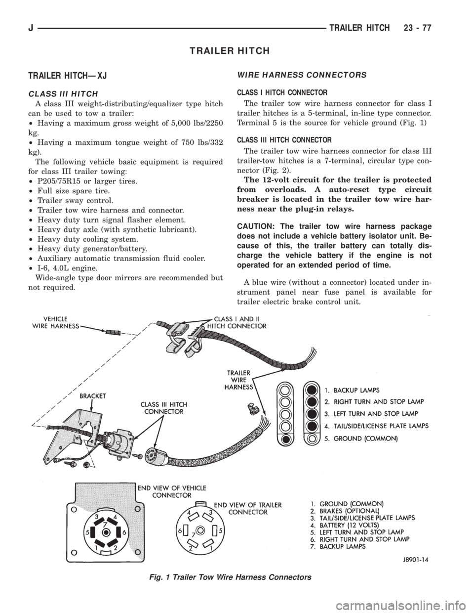
WIRE HARNESS CONNECTORS
CLASS I HITCH CONNECTOR
The trailer tow wire harness connector for class I
trailer hitches is a 5-terminal, in-line type connector.
Terminal 5 is the source for vehicle ground (Fig. 1)
CLASS III HITCH CONNECTOR
The trailer tow wire harness connector for class III
trailer-tow hitches is a 7-terminal, circular type con-
nector (Fig. 2).
The 12-volt circuit for the trailer is protected
from overloads. A auto-reset type circuit
breaker is located in the trailer tow wire har-
ness near the plug-in relays.
CAUTION: The trailer tow wire harness package
does not include a vehicle battery isolator unit. Be-
cause of this, the trailer battery can totally dis-
charge the vehicle battery if the engine is not
operated for an extended period of time.
A blue wire (without a connector) located under in-
strument panel near fuse panel is available for
trailer electric brake control unit.
Fig. 1 Trailer Tow Wire Harness Connectors
JTRAILER HITCH 23 - 77
Page 1902 of 2198
EVAPORATOR COIL:The coil is located in the
A/C housing. Its function is to remove heat and de-
humidify the air before it enters the vehicle.
FIN SENSING CYCLING CLUTCH SWITCH:
The switch is attached to the evaporator coil with the
temperature sensing probe inserted into the coil fins.
This switch controls evaporator temperature and pre-
vents condensate water on the evaporator coil from
freezing. It does this by sending signals to the Pow-
ertrain Control Module (PCM) to cycling the com-
pressor clutch on and off. This switch is used onXJ
only.
FILTER-DRIER:The drier is used to remove any
traces of moisture from the refrigerant system. A
sight glass is located on top of the filter drier. It is
used as a diagnostic tool to observe refrigerant flow.
HIGH PRESSURE RELIEF VALVE:The valve is
located on the filter drier. The valve is used to pre-
vent excessive high pressure build of 3445 to 4135
kPa (500 to 600 psi) and above. This prevents dam-
age to the compressor and other system components.
LOW-PRESSURE HIGH-PRESSURE CUT-OFF
SWITCH:The switch is located on the filter drier
and is wired in series with compressor clutch. When
the pressure drops down to 193 kPa (28 psi) the
switch interrupts the power to the compressor clutch.
When the pressure increases above 3100 to 3375 kPa
(450 to 490 psi) the switch interrupts the power to
the compressor clutch.
THERMOSTAT:The thermostat is located in the
evaporator housing. The thermostat temperature
sensing probe is inserted into the evaporator coil. Its
function is to cycles the compressor clutch on and off.
This switch controls temperature and prevents con-
densate water on the evaporator coil from freezing.
The thermostat is used on theYJonly.
REFRIGERANT LINES:The lines are used to
carry the refrigerant between the various system
components.
SERVICE PORTS:The high pressure service port
is located on the discharge line near the compressor.
The low pressure service port is located on the suc-
tion line near the compressor. These ports are used
to attach A/C gauges. After servicing the refrigerant
system, always install service port caps.
REFRIGERANT
XJ and YJ vehicles use a new type of refrigerant
called R-134a. It is a non-toxic, non-flammable, clear
color-less liquified gas.
R-134a refrigerant is not compatible with R-12 re-
frigerant. A small amount of R-12 in a R-134a system
will cause compressor failure, oil sludge or poor air
conditioning performance.R-134a refrigerant requires a special type of com-
pressor oil (SP20 PAG). When adding oil, make sure
that it is designed to be used in a R-134a system and
the SD7H15 compressor.
Service ports have been designed to ensure that
the system is not accidentally filled with R-12 refrig-
erant.
REFRIGERANT EQUIPMENT
WARNING: EYE PROTECTION MUST BE USED
WHEN SERVICING AN AIR CONDITIONING REFRIG-
ERANT SYSTEM. TURN OFF (ROTATE CLOCKWISE)
ALL VALVES ON THE EQUIPMENT BEING USED
BEFORE PROCEEDING WITH THIS OPERATION.
PERSONNEL INJURY CAN RESULT.
Chrysler Corporation recommends a (R-134a) recy-
cling device that meets SAE standard J2210 be used
when servicing the refrigerant system. Contact an
automotive service equipment supplier for refrigerant
recycling equipment that is available in your area.
Refer to the operating instructions provided with the
recycling equipment for proper operation.
MANIFOLD GAUGE SET
CAUTION: DO NOT use an R-12 manifold gauge set
on an R-134a system. The refrigerants are not com-
patible and system damage will result.
A manifold gauge set (Fig. 1) may be needed in
conjunction with the charging and or recovery/recy-
cling device. The service hoses on the gauge set being
used should have manual (turn wheel) or automatic
back flow valves at the service port connector ends.
This will prevent refrigerant from being release into
the atmosphere.
LOW PRESSURE GAUGE HOSE
The low pressure hose (BLUE with BLACK STRIP)
should be attached to the charging/service port. This
port is located at the right front of the engine com-
partment in the condenser-to-evaporator line.
HIGH PRESSURE GAUGE HOSE
The high pressure hose (RED with BLACK STRIP)
should be attached to the discharge/service port. This
port is located on the compressor plumbing or mani-
fold.
RECOVERY/RECYCLING/EVACUATION/
CHARGING HOSE
The center manifold hose (YELLOW or WHITE
with BLACK STRIP) is used to recover, evacuate and
charge the refrigerant system. When the low or high
pressure valves on the manifold gauge set are
opened, the refrigerant in the system will escape
through this hose.
JHEATING AND AIR CONDITIONING 24 - 7