lights JEEP CHEROKEE 2016 KL / 5.G Owner's Manual
[x] Cancel search | Manufacturer: JEEP, Model Year: 2016, Model line: CHEROKEE, Model: JEEP CHEROKEE 2016 KL / 5.GPages: 236, PDF Size: 11.24 MB
Page 145 of 236
• Push theRIGHTarrow button to access the information screens or submenu
screens of a main menu item.
• Push the LEFT
arrow button to access the information screens or submenu
screens of a main menu item.
• Push the OKbutton to access/select the information screens or submenu screens
of a main menu item. Push and hold the OKarrow button for two seconds to reset
displayed/selected features that can be reset.
Compass Calibration
This compass is self-calibrating, which eliminates the need to set the compass
manually. When the vehicle is new, the compass may appear erratic, and the
EVIC/DID will display “CAL” until the compass is calibrated.
You may also calibrate the compass by completing one or more 360 degree turns (in
an area free from large metal or metallic objects) until the “CAL” message displayed
in the EVIC/DID turns off. The compass will now function normally.
PROGRAMMABLE FEATURES
Uconnect Customer Programmable Features
The Uconnect system allows you to access Customer Programmable feature settings
through buttons on the touchscreen.
•
Push the MORE or SETTINGS button (Uconnect 5.0), or press the “Apps” button
(Uconnect 8.4) located near the bottom of the touchscreen, then press the “Settings”
button on the touchscreen to access the Settings screen. When making a selection,
scroll up or down until the preferred setting is highlighted, then press and release the
preferred setting until a check-mark appears next to the setting, showing that setting
has been selected. The following feature settings are available:
• Display • Engine Off Options
• Voice • Audio
• Clock • Phone/Bluetooth
• Safety & Driving Assistance • SiriusXM Setup
• Lights • Restore Settings
• Compass (Uconnect 5.0) • Clear Personal Data
• Doors & Locks • System Information
• Auto-On Comfort
NOTE:
Depending on the vehicles options, feature settings may vary.
ELECTRONICS
143
Page 157 of 236
REAR ELECTRONIC LOCKER (E-LOCKER) SYSTEM
The Rear E-Locker System features a mechanical locking rear differential to provide
better traction in the 4WD LOW position. The “REAR LOCK” button is on the
Selec-Terrain Knob.
Activating The Rear E-Locker
To activate the Rear E-Locker System, the following conditions must be met:
• The 4WD system must be in 4WD LOW.
• The ignition switch in the ON position or the engine running.
• Vehicle speed must be below 15 MPH (24 km/h).
• To engage Rear E-Locker, push the REAR LOCK button once.
Deactivating The Rear E-Locker System
To deactivate the Rear E-Locker System, the following conditions must be met:
• Rear E-Locker must be engaged, and the REAR LOCK indicator light on.
• The ignition switch in the ON position or the engine running.
• To disengage Rear E-Locker , push the REAR LOCK button once.
NOTE:
• It may also be necessary to drive slowly steering back and forth to completeengagement and disengagement of the E- Locker.
• When engaging Rear E-Locker, the indicator lights in the instrument cluster and on the REAR LOCK button will begin to flash. When the shift is complete the REAR
LOCK indicator lights will remain on.
• When disengaging Rear E-Locker, the indicator lights in the instrument cluster and on the REAR LOCK button will begin to flash. When the shift is complete the
REAR LOCK indicator lights will remain off.
• Shifting into or out of Rear E-Locker is possible with the vehicle completely stopped; however, difficulty may occur due to the mating clutch teeth not being
properly aligned. Several attempts may be required for clutch teeth alignment and
shift completion to occur. The preferred method is for the vehicle to be rolling,
below 15 MPH (24 km/h), while including right and left steering maneuvers to
allow for the clutch teeth to align.
• The Rear E-Locker System must be disengaged prior to taking the vehicle out of 4X4 LOW range. If 4X4 LOW shift conditions/interlocks are not met, a message will
flash from the Electronic Vehicle Information Center (EVIC)/Driver Information
Display with instructions on how to complete the requested shift.
OFF-ROAD CAPABILITIES
155
Page 163 of 236
1. Bring the vehicle to a complete stop and shift the transmission to PARK.
2. Turn the engine OFF.
3. Turn the ignition switch to the ON/RUN position, but do not start the engine.
4. Press and hold the brake pedal.
5. Shift the transmission into NEUTRAL.
6. Using a ballpoint pen or similar object, push and hold the recessed NEUTRAL (N)button (located by the selector switch) for four seconds. The light behind the
NEUTRAL (N) symbol will blink, indicating shift in progress. The light will stop
blinking (stay on solid) when the shift to NEUTRAL (N) is complete.
7. After the shift is completed and the NEUTRAL (N) light stays on, release the NEUTRAL (N) button.
8. Start the engine.
9. Release the parking brake.
10. Shift the transmission into REVERSE.
11. Release the brake pedal for five seconds and ensure that there is no vehicle movement.
12. Shift the transmission to NEUTRAL.
13. Apply the parking brake.
14. Shift the transmission into PARK, turn the engine OFF, and remove the key fob.
15. Attach the vehicle to the tow vehicle using a suitable tow bar.
16. Turn the ignition to the ON/RUN position, but do not start the engine.
17. Press and hold the brake pedal.
18. Release the parking brake.
19. Turn the ignition OFF, remove the Key Fob, and release the brake pedal.
NOTE:
• Steps 1 through 5 are requirements that must be met before pushing the NEUTRAL (N) button, and must continue to be met until the shift has been
completed. If any of these requirements are not met before pushing the NEUTRAL
(N) button or are no longer met during the shift, then the NEUTRAL (N) indicator
light will flash continuously until all requirements are met or until the NEUTRAL
(N) button is released.
• The ignition switch must be in the ON/RUN position for a shift to take place and for the position indicator lights to be operable. If the ignition switch is not in the
ON/RUN position, the shift will not take place and no position indicator lights will
be on or flashing.
• A flashing NEUTRAL (N) position indicator light indicates that shift requirements have not been met.
UTILITY
161
Page 164 of 236
Shifting Out Of NEUTRAL (N)
Use the following procedure to prepare your vehicle for normal usage.
1. Bring the vehicle to a complete stop, leaving it connected to the tow vehicle.
2. Apply the parking brake.
3. Turn the ignition switch to the ON/RUN position, but do not start the engine.
4. Press and hold the brake pedal.
5. Shift the transmission into NEUTRAL.
6. Using a ballpoint pen or similar object, push and hold the recessed power transferunit NEUTRAL (N) button (located by the selector switch) for one second.
7.
When the NEUTRAL (N) indicator light turns off, release the NEUTRAL (N) button.
8. After the NEUTRAL (N) button has been released, the power transfer unit will shift to the position indicated by the selector switch.
NOTE:
When shifting the power transfer unit out of NEUTRAL (N), the engine should remain
OFF to avoid gear clash.
9. Shift the transmission into PARK.
10. Release the brake pedal.
11. Disconnect vehicle from the tow vehicle.
12. Start the engine.
13. Press and hold the brake pedal.
14. Release the parking brake.
15. Shift the transmission into DRIVE, release the brake pedal, and check that the vehicle operates normally.
16. Re-enable the Auto Park Brake feature, if desired.
NOTE:
• Steps 1 through 5 are requirements that must be met before pushing the NEUTRAL (N) button, and must continue to be met until the shift has been
completed. If any of these requirements are not met before pushing the NEUTRAL
(N) button or are no longer met during the shift, the NEUTRAL (N) indicator light
will flash continuously until all requirements are met or until the NEUTRAL (N)
button is released.
• The ignition switch must be in the ON/RUN position for a shift to take place and for the position indicator lights to be operable. If the ignition switch is not in the
ON/RUN position, the shift will not take place and no position indicator lights will
be on or flashing.
• A flashing NEUTRAL (N) position indicator light indicates that shift requirements have not been met.
UTILITY
162
Page 165 of 236
ROADSIDE ASSISTANCE
Dial toll-free 1-800-521-2779 for U.S. Residents or 1-800-363-4869 for Canadian
Residents.
• Provide your name, vehicle identification number, license plate number, and yourlocation, including the telephone number from which you are calling.
• Briefly describe the nature of the problem and answer a few simple questions.
• You will be given the name of the service provider and an estimated time of arrival. If you feel you are in an “unsafe situation”, please let us know. With your consent,
we will contact local police or safety authorities.
INSTRUMENT CLUSTER WARNING LIGHTS
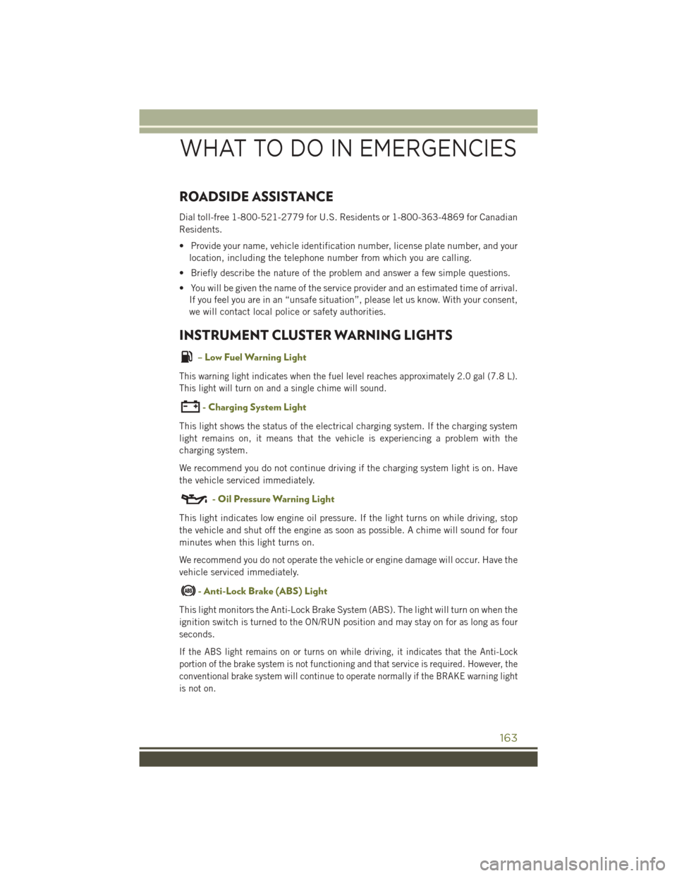
– Low Fuel Warning Light
This warning light indicates when the fuel level reaches approximately 2.0 gal (7.8 L).
This light will turn on and a single chime will sound.
- Charging System Light
This light shows the status of the electrical charging system. If the charging system
light remains on, it means that the vehicle is experiencing a problem with the
charging system.
We recommend you do not continue driving if the charging system light is on. Have
the vehicle serviced immediately.
- Oil Pressure Warning Light
This light indicates low engine oil pressure. If the light turns on while driving, stop
the vehicle and shut off the engine as soon as possible. A chime will sound for four
minutes when this light turns on.
We recommend you do not operate the vehicle or engine damage will occur. Have the
vehicle serviced immediately.
- Anti-Lock Brake (ABS) Light
This light monitors the Anti-Lock Brake System (ABS). The light will turn on when the
ignition switch is turned to the ON/RUN position and may stay on for as long as four
seconds.
If the ABS light remains on or turns on while driving, it indicates that the Anti-Lock
portion of the brake system is not functioning and that service is required. However, the
conventional brake system will continue to operate normally if the BRAKE warning light
is not on.
WHAT TO DO IN EMERGENCIES
163
Page 172 of 236
INSTRUMENT CLUSTER INDICATOR LIGHTS
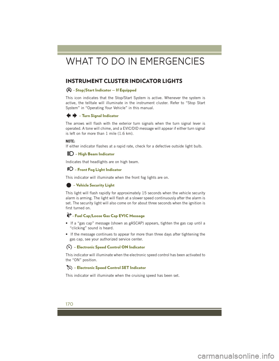
A- Stop/Start Indicator — If Equipped
This icon indicates that the Stop/Start System is active. Whenever the system is
active, the telltale will illuminate in the instrument cluster. Refer to “Stop Start
System” in “Operating Your Vehicle” in this manual.
– Turn Signal Indicator
The arrows will flash with the exterior turn signals when the turn signal lever is
operated. A tone will chime, and a EVIC/DID message will appear if either turn signal
is left on for more than 1 mile (1.6 km).
NOTE:
If either indicator flashes at a rapid rate, check for a defective outside light bulb.
– High Beam Indicator
Indicates that headlights are on high beam.
– Front Fog Light Indicator
This indicator will illuminate when the front fog lights are on.
– Vehicle Security Light
This light will flash rapidly for approximately 15 seconds when the vehicle security
alarm is arming. The light will flash at a slower speed continuously after the alarm is
set. The security light will also come on for about three seconds when the ignition is
first turned on.
- Fuel Cap/Loose Gas Cap EVIC Message
• If a “gas cap” message (shown as gASCAP) appears, tighten the gas cap until a“clicking” sound is heard.
• If the message continues to appear for more than three days after tightening the gas cap, see your authorized service center.
– Electronic Speed Control ON Indicator
This indicator will illuminate when the electronic speed control has been activated to
the “ON” position.
– Electronic Speed Control SET Indicator
This indicator will illuminate when the cruising speed has been set.
WHAT TO DO IN EMERGENCIES
170
Page 174 of 236
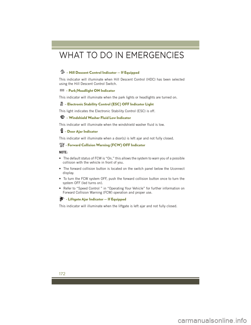
– Hill Descent Control Indicator — If Equipped
This indicator will illuminate when Hill Descent Control (HDC) has been selected
using the Hill Descent Control Switch.
– Park/Headlight ON Indicator
This indicator will illuminate when the park lights or headlights are turned on.
– Electronic Stability Control (ESC) OFF Indicator Light
This light indicates the Electronic Stability Control (ESC) is off.
– Windshield Washer Fluid Low Indicator
This indicator will illuminate when the windshield washer fluid is low.
– Door Ajar Indicator
This indicator will illuminate when a door(s) is left ajar and not fully closed.
- Forward Collision Warning (FCW) OFF Indicator
NOTE:
• The default status of FCW is “On,” this allows the system to warn you of a possiblecollision with the vehicle in front of you.
• The forward collision button is located on the switch panel below the Uconnect display.
• To turn the FCW system OFF, push the forward collision button once to turn the system OFF (led turns on).
• Refer to “Speed Control ” in “Operating Your Vehicle” for further information on Forward Collision Warning (FCW) operation and proper use.
- Liftgate Ajar Indicator — If Equipped
This indicator will illuminate when the liftgate is left ajar and not fully closed.
WHAT TO DO IN EMERGENCIES
172
Page 202 of 236
FLEXIBLE FUEL (2.4L ENGINE ONLY) — IF EQUIPPED
E-85 General Information
The information in this section is unique for Flexible Fuel vehicles only. These
vehicles can be identified by a unique fuel filler door label that statesEthanol (E-85)
or Unleaded Gasoline Only and a yellow fuel cap. Refer to the Owner’s Manual on the
DVD for further information.
CAUTION!
Only vehicles with the E-85 fuel filler door label or a yellow gas cap can operate on
E-85.
MAINTENANCE PROCEDURES
For information on the maintenance procedures for your vehicle, please refer to
“Maintenance Procedures” in “Maintaining Your Vehicle” in your Owner’s Manual or
applicable supplement on the DVD for further details.
MAINTENANCE SCHEDULE
Your vehicle is equipped with an automatic oil change indicator system. The oil
change indicator system will remind you that it is time to take your vehicle in for
scheduled maintenance.
Based on engine operation conditions, the oil change indicator message will
illuminate. This means that service is required for your vehicle. Operating conditions
such as frequent short-trips, trailer tow, extremely hot or cold ambient temperatures
will influence when the “Oil Change Required” message is displayed. Severe
Operating Conditions can cause the change oil message to illuminate as early as
3,500 miles (5,600 km) since last reset. Have your vehicle serviced as soon as
possible, within the next 500 miles (805 km).
Your authorized dealer will reset the oil change indicator message after completing the
scheduled oil change. If a scheduled oil change is performed by someone other than
your authorized dealer, the message can be reset by referring to the steps described
under “Instrument Cluster Warning Lights” in “What To Do In Emergencies” in this
guide or “Electronic Vehicle Information Center (EVIC)” or “Driver Information Display
(DID)” in “Understanding Your Instrument Panel” in your Owners Manual on the DVD for
further information.
MAINTAINING YOUR VEHICLE
200
Page 203 of 236
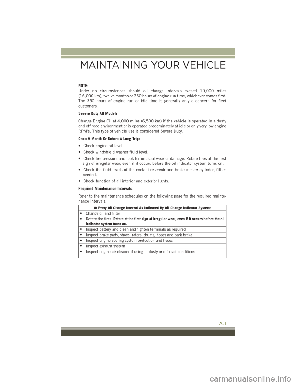
NOTE:
Under no circumstances should oil change intervals exceed 10,000 miles
(16,000 km), twelve months or 350 hours of engine run time, whichever comes first.
The 350 hours of engine run or idle time is generally only a concern for fleet
customers.
Severe Duty All Models
Change Engine Oil at 4,000 miles (6,500 km) if the vehicle is operated in a dusty
and off road environment or is operated predominately at idle or only very low engine
RPM’s. This type of vehicle use is considered Severe Duty.
Once A Month Or Before A Long Trip:
• Check engine oil level.
• Check windshield washer fluid level.
• Check tire pressure and look for unusual wear or damage. Rotate tires at the firstsign of irregular wear, even if it occurs before the oil indicator system turns on.
• Check the fluid levels of the coolant reservoir and brake master cylinder, fill as needed.
• Check function of all interior and exterior lights.
Required Maintenance Intervals.
Refer to the maintenance schedules on the following page for the required mainte-
nance intervals.
At Every Oil Change Interval As Indicated By Oil Change Indicator System:
• Change oil and filter
• Rotate the tires. Rotate at the first sign of irregular wear, even if it occurs before the oil
indicator system turns on.
• Inspect battery and clean and tighten terminals as required
• Inspect brake pads, shoes, rotors, drums, hoses and park brake
• Inspect engine cooling system protection and hoses
• Inspect exhaust system
• Inspect engine air cleaner if using in dusty or off-road conditions
MAINTAINING YOUR VEHICLE
201
Page 208 of 236
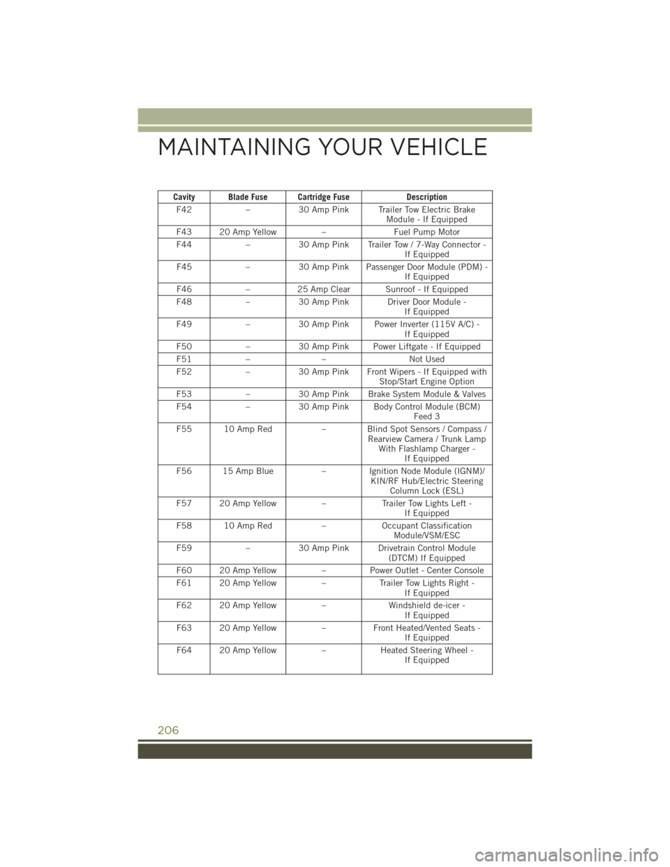
Cavity Blade Fuse Cartridge FuseDescription
F42 –30 Amp Pink Trailer Tow Electric Brake
Module - If Equipped
F43 20 Amp Yellow –Fuel Pump Motor
F44 –30 Amp Pink Trailer Tow / 7-Way Connector -
If Equipped
F45 –30 Amp Pink Passenger Door Module (PDM) -
If Equipped
F46 –25 Amp Clear Sunroof - If Equipped
F48 –30 Amp Pink Driver Door Module -
If Equipped
F49 –30 Amp Pink Power Inverter (115V A/C) -
If Equipped
F50 –30 Amp Pink Power Liftgate - If Equipped
F51 – – Not Used
F52 –30 Amp Pink Front Wipers - If Equipped with
Stop/Start Engine Option
F53 –30 Amp Pink Brake System Module & Valves
F54 –30 Amp Pink Body Control Module (BCM)
Feed 3
F55 10 Amp Red – Blind Spot Sensors / Compass /
Rearview Camera / Trunk LampWith Flashlamp Charger - If Equipped
F56 15 Amp Blue – Ignition Node Module (IGNM)/
KIN/RF Hub/Electric SteeringColumn Lock (ESL)
F57 20 Amp Yellow –Trailer Tow Lights Left -
If Equipped
F58 10 Amp Red –Occupant Classification
Module/VSM/ESC
F59 –30 Amp Pink Drivetrain Control Module
(DTCM) If Equipped
F60 20 Amp Yellow –Power Outlet - Center Console
F61 20 Amp Yellow –Trailer Tow Lights Right -
If Equipped
F62 20 Amp Yellow –Windshield de-icer -
If Equipped
F63 20 Amp Yellow –Front Heated/Vented Seats -
If Equipped
F64 20 Amp Yellow –Heated Steering Wheel -
If Equipped
MAINTAINING YOUR VEHICLE
206