instrument panel JEEP CHEROKEE 2016 KL / 5.G User Guide
[x] Cancel search | Manufacturer: JEEP, Model Year: 2016, Model line: CHEROKEE, Model: JEEP CHEROKEE 2016 KL / 5.GPages: 236, PDF Size: 11.24 MB
Page 19 of 236
Seat Belt Pretensioner
• The front seat belt system is equipped with pretensioning devices that aredesigned to remove slack from the seat belt in the event of a collision.
• A deployed pretensioner or a deployed air bag must be replaced immediately.
WARNING!
• In a collision, you and your passengers can suffer much greater injuries if you are not properly buckled up. You can strike the interior of your vehicle or other
passengers, or you can be thrown out of the vehicle. Always be sure you and
others in your vehicle are buckled up properly.
• A shoulder belt placed behind you will not protect you from injury during a
collision. You are more likely to hit your head in a collision if you do not wear
your shoulder belt. The lap and shoulder belt are meant to be used together.
•
A seat belt that is too loose will not protect you properly. In a sudden stop, you
could move too far forward, increasing the possibility of injury. Wear your seat belt
snugly.
•A frayed or torn seat belt could rip apart in a collision and leave you with no
protection. Inspect the seat belt system periodically, checking for cuts, frays, or
loose parts. Damaged parts must be replaced immediately. Do not disassemble or
modify the system. Seat belt assemblies must be replaced after a collision.
SUPPLEMENTAL RESTRAINT SYSTEM (SRS) —
AIR BAGS
Air Bag System Components
Your vehicle may be equipped with the following air bag system components:
• Occupant Restraint Controller (ORC)
• Air Bag Warning Light
• Steering Wheel and Column
• Instrument Panel
• Knee Impact Bolsters
• Advanced Front Air Bags
• Supplemental Side Air Bags
• Supplemental Knee Air Bags
• Front and Side Impact Sensors
• Seat Belt Pretenioners
• Seat Belt Buckle Switch
• Seat Track Position Sensors
• Occupant Classification System
GETTING STARTED
17
Page 22 of 236
Lighter Weight Passengers (Including Small Adults)
When a lighter weight passenger, including a small adult, occupies the front passenger
seat, the OCS may reduce the inflation rate of the Passenger Advanced Front Air Bag.
This does not mean that the OCS is working improperly.
Do not decrease OR increase the front passenger’s seated weight on the front
passenger seat
The front passenger’s seated weight must be properly positioned on the front
passenger seat. Failure to do so may result in serious injury or death. The OCS
determines the most probable classification of the occupant that it detects. The OCS
will detect the front passenger’s decreased or increased seated weight, which may
result in an adjusted inflation rate of the Passenger Advanced Front Air Bag in a
collision. This does not mean that the OCS is working improperly. Decreasing the
front passenger’s seated weight on the front passenger seat may result in a
reduced-power deployment of the Passenger Advanced Front Air Bag. Increasing the
front passenger’s seated weight on the front passenger seat may result in a full-power
deployment of the Passenger Advanced Front Air Bag. Examples of improper front
passenger seating include:
• The front passenger’s weight is transferred to another part of the vehicle (like thedoor, arm rest or instrument panel).
• The front passenger leans forward, sideways, or turns to face the rear of the vehicle.
• The front passenger’s seatback is not in the full upright position.
• The front passenger carries or holds an object while seated (e.g., backpack, box, etc.).
• Objects are lodged under the front passenger seat.
• Objects are lodged between the front passenger seat and center console.
• Accessories that may change the seated weight on the front passenger seat are attached to the front passenger seat.
• Anything that may decrease or increase the front passenger’s seated weight.
GETTING STARTED
20
Page 24 of 236
• Do not add a secondary seat cover or mat.
• At no time should any Supplemental Restraint System (SRS) component or SRSrelated component or fastener be modified or replaced with any part except those
which are approved by FCA US LLC.
Supplemental Knee Air Bags
This vehicle is equipped with a Supplemental Driver Knee Air Bag mounted in the
instrument panel below the steering column and a Supplemental Passenger Knee Air
Bag mounted in the instrument panel below the glove compartment. The Supple-
mental Knee Air Bags provide enhanced protection during a frontal impact by
working together with the seat belts, pretensioners, and Advanced Front Air Bags.
WARNING!
•Relying on the air bags alone could lead to more severe injuries in a collision. The
air bags work with your seat belt to restrain you properly. In some collisions, the
air bags won't deploy at all. Always wear your seat belts even though you have air
bags.
• Being too close to the steering wheel or instrument panel during Advanced Front Air Bag deployment could cause serious injury, including death. Air bags
need room to inflate. Sit back, comfortably extending your arms to reach the
steering wheel or instrument panel.
• No objects should be placed over or near the air bag on the instrument panel
or steering wheel because any such objects could cause harm if the vehicle is
in a collision severe enough to cause the air bag to inflate.
Supplemental Side Air Bags
• This vehicle is equipped with Supplemental Seat-Mounted Side Air Bags (SABs)
located in the outboard side of the front and rear (in vehicles equipped with
outboard rear seat SABs) seats. The SABs are marked with a SRS AIRBAG or
AIRBAG label sewn into the outboard side of the seats.
• This vehicle is equipped with Supplemental Side Air Bag Inflatable Curtains (SABICs) located above the side windows. The trim covering the SABICs is labeled
SRS AIRBAG or AIRBAG. The SABICs may help reduce the risk of partial or
complete ejection of vehicle occupants through side windows in certain side
impact events.
• The SABICs and SABs (“Side Air Bags”) are designed to activate in certain side impacts and certain rollover events. The Occupant Restraint Controller (“ORC”)
determines whether the deployment of the Side Air Bags in a particular side
impact or rollover event is appropriate, based on the severity and type of collision.
Vehicle damage by itself is not a good indicator of whether or not Side Air Bags
should have deployed.
GETTING STARTED
22
Page 26 of 236
Air Bag Warning Light
• The air bags must be ready to inflate for your protection in a collision. TheOccupant Restraint Controller (ORC) monitors the internal circuits and intercon-
necting wiring associated with air bag system electrical components.
• The ORC monitors the readiness of the electronic parts of the air bag system whenever the ignition switch is in the START or ON/RUN position. If the ignition
switch is in the OFF position or in the ACC position, the air bag system is not on
and the air bags will not inflate.
• The ORC turns on the Air Bag Warning Light in the instrument panel for approximately four to eight seconds for a self-check when the ignition switch is
first turned to the ON/RUN position. After the self-check, the Air Bag Warning
Light will turn off. If the ORC detects a malfunction in any part of the system, it
turns on the Air Bag Warning Light, either momentarily or continuously. A single
chime will sound to alert you if the light comes on again after initial startup.
• If the Air Bag Warning Light in the instrument panel is not on during the four to eight seconds when the ignition switch is first turned to the ON/RUN position,
stays on, or turns on while driving, have the vehicle serviced by an authorized
service center immediately.
NOTE:
If the speedometer, tachometer, or any engine related gauges are not working, the
Occupant Restraint Controller (ORC) may also be disabled. In this condition the air
bags may not be ready to inflate for your protection. Have an authorized dealer
service the air bag system immediately.
Event Data Recorder (EDR)
This vehicle is equipped with an event data recorder (EDR). The main purpose of an
EDR is to record, in certain crash or near crash-like situations, such as an air bag
deployment or hitting a road obstacle, data that will assist in understanding how a
vehicle’s systems performed. The EDR is designed to record data related to vehicle
dynamics and safety systems for a short period of time, typically 30 seconds or less.
The EDR in this vehicle is designed to record such data as:
• How various systems in your vehicle were operating;
• Whether or not the driver and passenger safety belts were buckled/fastened;
• How far (if at all) the driver was depressing the accelerator and/or brake pedal; and,
• How fast the vehicle was traveling.
These data can help provide a better understanding of the circumstances in which
crashes and injuries occur.
GETTING STARTED
24
Page 35 of 236
Memory Seat
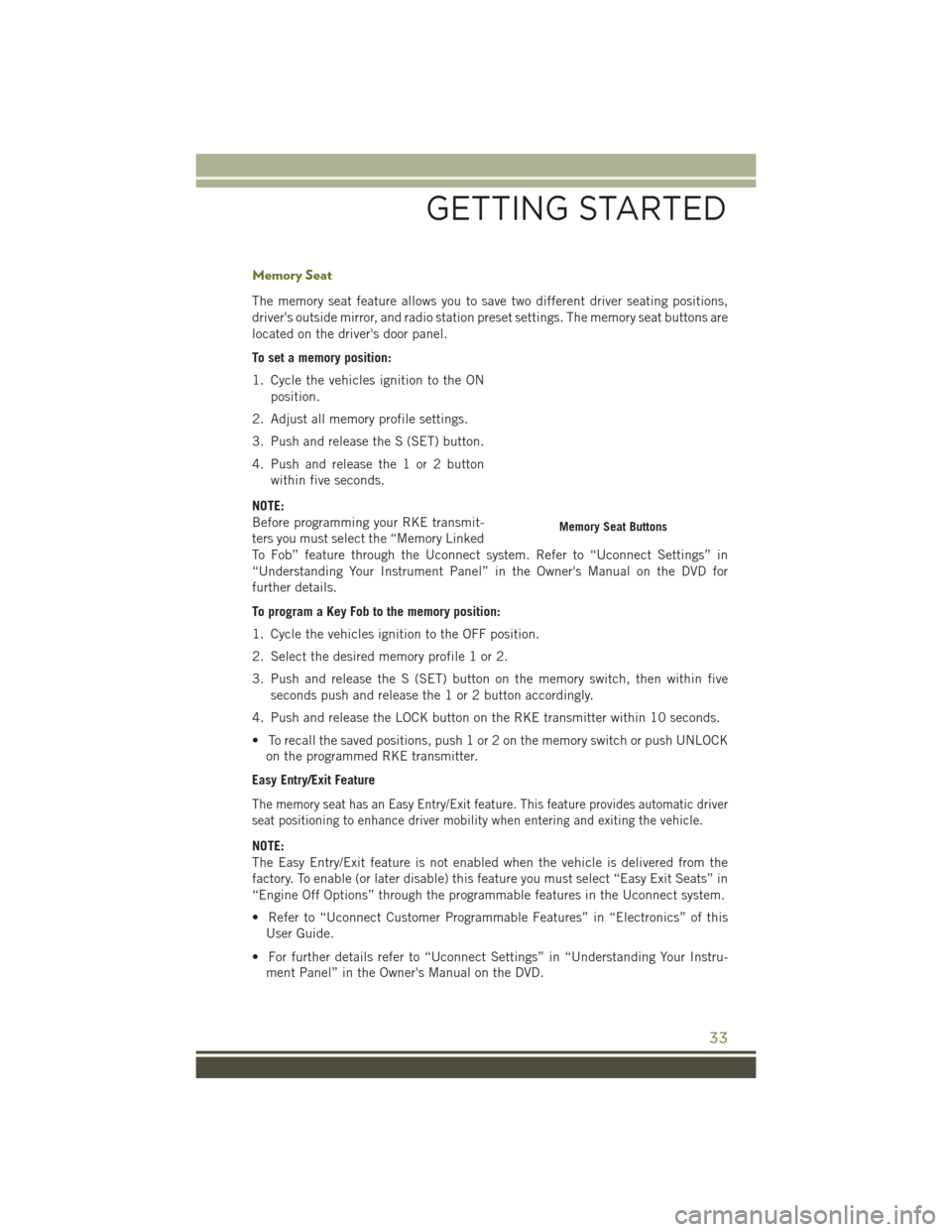
The memory seat feature allows you to save two different driver seating positions,
driver's outside mirror, and radio station preset settings. The memory seat buttons are
located on the driver's door panel.
To set a memory position:
1. Cycle the vehicles ignition to the ONposition.
2. Adjust all memory profile settings.
3. Push and release the S (SET) button.
4. Push and release the 1 or 2 button within five seconds.
NOTE:
Before programming your RKE transmit-
ters you must select the “Memory Linked
To Fob” feature through the Uconnect system. Refer to “Uconnect Settings” in
“Understanding Your Instrument Panel” in the Owner's Manual on the DVD for
further details.
To program a Key Fob to the memory position:
1. Cycle the vehicles ignition to the OFF position.
2. Select the desired memory profile 1 or 2.
3. Push and release the S (SET) button on the memory switch, then within five seconds push and release the 1 or 2 button accordingly.
4. Push and release the LOCK button on the RKE transmitter within 10 seconds.
• To recall the saved positions, push 1 or 2 on the memory switch or push UNLOCK on the programmed RKE transmitter.
Easy Entry/Exit Feature
The memory seat has an Easy Entry/Exit feature. This feature provides automatic driver
seat positioning to enhance driver mobility when entering and exiting the vehicle.
NOTE:
The Easy Entry/Exit feature is not enabled when the vehicle is delivered from the
factory. To enable (or later disable) this feature you must select “Easy Exit Seats” in
“Engine Off Options” through the programmable features in the Uconnect system.
• Refer to “Uconnect Customer Programmable Features” in “Electronics” of this User Guide.
• For further details refer to “Uconnect Settings” in “Understanding Your Instru- ment Panel” in the Owner's Manual on the DVD.
Memory Seat Buttons
GETTING STARTED
33
Page 39 of 236
HEATED/VENTILATED SEATS
Front Heated Seats
If your vehicle is equipped with front heated seats, the control buttons are located
within the Uconnect system. You can gain access to the control buttons through the
climate screen or the controls screen.
• Press the heated seat button
once to turn the HI setting ON.
• Press the heated seat button
a second time to turn the LO setting ON.
• Press the heated seat button
a third time to turn the heating elements OFF.
If the HI-level setting is selected, the system will automatically switch to LO-level
after approximately 60 minutes of continuous operation. At that time, the display will
change from HI to LO, indicating the change. The LO-level setting will turn OFF
automatically after approximately 45 minutes.
NOTE:
The engine must be running for the heated seats to operate.
Vehicles Equipped With Remote Start
On models that are equipped with remote start, the heated seats can be programed
to come on during a remote start.
This feature can be programmed through the Uconnect system. Refer to “Uconnect
Settings” in “Understanding Your Instrument Panel” in the Owner’s Manual on the
DVD for further information.
WARNING!
• Persons who are unable to feel pain to the skin because of advanced age, chronic illness, diabetes, spinal cord injury, medication, alcohol use, exhaus-
tion or other physical condition must exercise care when using the seat heater.
It may cause burns even at low temperatures, especially if used for long periods
of time.
• Do not place anything on the seat or seatback that insulates against heat, such
as a blanket or cushion. This may cause the seat heater to overheat. Sitting in
a seat that has been overheated could cause serious burns due to the increased
surface temperature of the seat.
GETTING STARTED
37
Page 40 of 236
Front Ventilated Seats
If your vehicle is equipped with ventilated seats, the seat cushion and seat back will
have fans that draw the air from the passenger compartment and move air through
fine perforations in the seat cover to help keep the driver and front passenger cooler
in higher ambient temperatures. The fans operate at two speeds, HI and LO.
The front ventilated seats control buttons are located within the Uconnect system.
You can gain access to the control buttons through the climate screen or the controls
screen.
• Press the ventilated seat button
once to choose HI.
• Press the ventilated seat button
a second time to choose LO.
• Press the ventilated seat button
a third time to turn the ventilated seat OFF.
NOTE:
The engine must be running for the ventilated seats to operate.
Vehicles Equipped With Remote Start
On models that are equipped with remote start, the ventilated seats can be
programed to come on during a remote start.
This feature can be programmed through the Uconnect system. Refer to “Uconnect
Settings” in “Understanding Your Instrument Panel” in the Owner's Manual on the DVD.
HEATED STEERING WHEEL
If your vehicle is equipped with a heated steering wheel, it contains a heating
element that will keep your hands warm in cold weather. The heated steering wheel
has only one temperature setting. Once the heated steering wheel has been turned on
it can operate for up to 120 minutes before automatically shutting off. The heated
steering wheel can shut off early or may not turn on when the steering wheel is
already warm.
The heated steering wheel control button is located within the Uconnect system. You
can gain access to the control button through the climate screen or the controls
screen.
• Press the heated steering wheel button
once to turn the heating element ON.
• Press the heated steering wheel button
a second time to turn the heating
element OFF.
NOTE:
The engine must be running for the heated steering wheel to operate.
GETTING STARTED
38
Page 41 of 236
Vehicles Equipped With Remote Start
On models that are equipped with remote start, the heated steering wheel can be
programmed to come on during a remote start through the Uconnect system. Refer to
“Uconnect Settings” in “Understanding Your Instrument Panel” in the Owner’s Manual
on the DVD for further information.
WARNING!
• Persons who are unable to feel pain to the skin because of advanced age,chronic illness, diabetes, spinal cord injury, medication, alcohol use, exhaus-
tion, or other physical conditions must exercise care when using the steering
wheel heater. It may cause burns even at low temperatures, especially if used
for long periods.
• Do not place anything on the steering wheel that insulates against heat, such
as a blanket or steering wheel covers of any type and material. This may cause
the steering wheel heater to overheat.
TILT/TELESCOPING STEERING COLUMN
This feature allows you to tilt the steering column upward or downward. It also allows
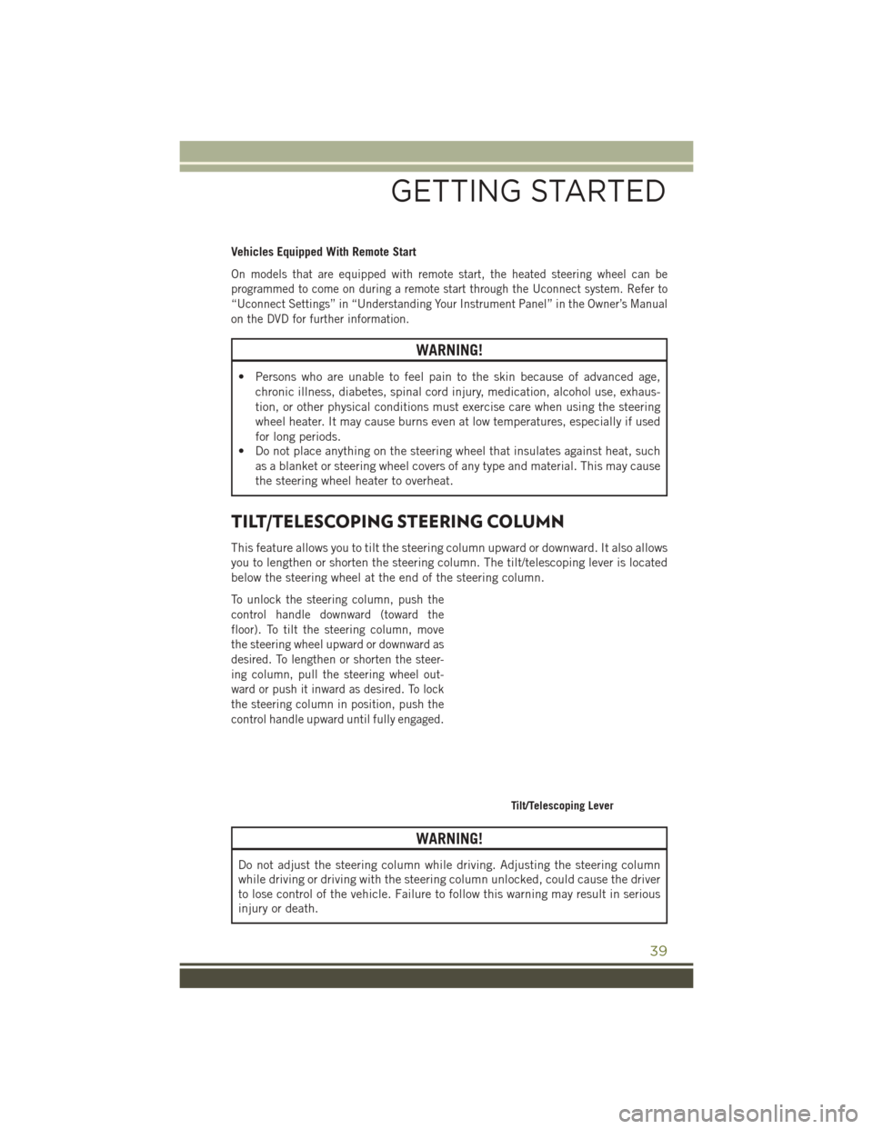
you to lengthen or shorten the steering column. The tilt/telescoping lever is located
below the steering wheel at the end of the steering column.
To unlock the steering column, push the
control handle downward (toward the
floor). To tilt the steering column, move
the steering wheel upward or downward as
desired. To lengthen or shorten the steer-
ing column, pull the steering wheel out-
ward or push it inward as desired. To lock
the steering column in position, push the
control handle upward until fully engaged.
WARNING!
Do not adjust the steering column while driving. Adjusting the steering column
while driving or driving with the steering column unlocked, could cause the driver
to lose control of the vehicle. Failure to follow this warning may result in serious
injury or death.
Tilt/Telescoping Lever
GETTING STARTED
39
Page 43 of 236
HEADLIGHT SWITCH
Automatic Headlights/Parking
Lights/Headlights
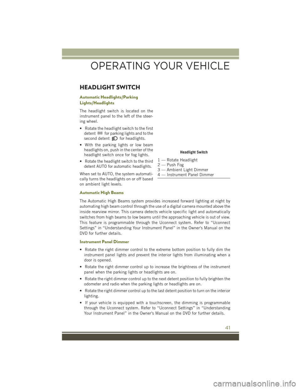
The headlight switch is located on the
instrument panel to the left of the steer-
ing wheel.
• Rotate the headlight switch to the firstdetent
for parking lights and to the
second detent
for headlights.
• With the parking lights or low beam headlights on, push in the center of the
headlight switch once for fog lights.
•
Rotate the headlight switch to the third
detent AUTO for automatic headlights.
When set to AUTO, the system automati-
cally turns the headlights on or off based
on ambient light levels.
Automatic High Beams
The Automatic High Beams system provides increased forward lighting at night by
automating high beam control through the use of a digital camera mounted above the
inside rearview mirror. This camera detects vehicle specific light and automatically
switches from high beams to low beams until the approaching vehicle is out of view.
This feature is programmable through the Uconnect system. Refer to “Uconnect
Settings” in “Understanding Your Instrument Panel” in the Owner's Manual on the
DVD for further details.
Instrument Panel Dimmer
• Rotate the right dimmer control to the extreme bottom position to fully dim the
instrument panel lights and prevent the interior lights from illuminating when a
door is opened.
• Rotate the right dimmer control up to increase the brightness of the instrument panel when the parking lights or headlights are on.
• Rotate the right dimmer control up to the next detent position to fully brighten the odometer and radio when the parking lights or headlights are on.
• Rotate the right dimmer control up to the last detent position to turn on the interior lighting.
• If your vehicle is equipped with a touchscreen, the dimming is programmable through the Uconnect system. Refer to “Uconnect Settings” in “Understanding
Your Instrument Panel” in the Owner's Manual on the DVD for further details.
Headlight Switch
1 — Rotate Headlight
2 — Push Fog
3 — Ambient Light Dimmer
4 — Instrument Panel Dimmer
OPERATING YOUR VEHICLE
41
Page 45 of 236
ELECTRONIC SPEED CONTROL
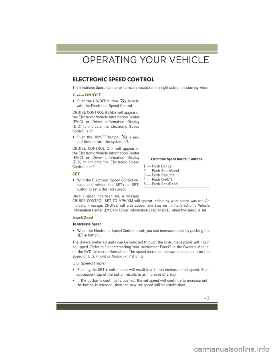
The Electronic Speed Control switches are located on the right side of the steering wheel.
Cruise ON/OFF
• Push the ON/OFF buttonto acti-
vate the Electronic Speed Control.
CRUISE CONTROL READY will appear in
the Electronic Vehicle Information Center
(EVIC) or Driver Information Display
(DID) to indicate the Electronic Speed
Control is on.
• Push the ON/OFF button
a sec-
ond time to turn the system off.
CRUISE CONTROL OFF will appear in
the Electronic Vehicle Information Center
(EVIC) or Driver Information Display
(DID) to indicate the Electronic Speed
Control is off.
SET
• With the Electronic Speed Control on, push and release the SET+ or SET-
button to set a desired speed.
Once a speed has been set, a message
CRUISE CONTROL SET TO MPH/KM will appear indicating what speed was set. An
indicator message, CRUISE will also appear and stay on in the Electronic Vehicle
Information Center (EVIC) or Driver Information Display (DID) when the speed is set.
Accel/Decel
To Increase Speed
• When the Electronic Speed Control is set, you can increase speed by pushing theSET +button.
The drivers preferred units can be selected through the instrument panel settings if
equipped. Refer to “Understanding Your Instrument Panel” in the Owner’s Manual
on the DVD for more information. The speed increment shown is dependant on the
speed of U.S. (mph) or Metric (km/h) units:
U.S. Speed (mph)
• Pushing the SET +button once will result in a 1 mph increase in set speed. Each
subsequent tap of the button results in an increase of 1 mph.
• If the button is continually pushed, the set speed will continue to increase until the button is released, then the new set speed will be established.
Electronic Speed Control Switches
1 — Push Cancel
2 — Push Set+/Accel
3 — Push Resume
4 — Push On/Off
5 — Push Set-/Decel
OPERATING YOUR VEHICLE
43