tow JEEP CHEROKEE 2017 KL / 5.G Repair Manual
[x] Cancel search | Manufacturer: JEEP, Model Year: 2017, Model line: CHEROKEE, Model: JEEP CHEROKEE 2017 KL / 5.GPages: 615, PDF Size: 5.72 MB
Page 400 of 615
Replacing Exterior Bulbs
Bi-Xenon High Intensity Discharge (HID)
Headlamps — If Equipped
The headlamps contain a type of high voltage discharge
light source. High voltage can remain in the circuit even
with the headlamp switch off. Because of this, you should
not attempt to service a HID headlamp light source your-
self. If an HID headlamp light source fails, take your
vehicle to an authorized dealer for service.
NOTE:On vehicles equipped with HID headlamps, when
the headlamps are turned on, there is a blue hue to the
lights. This diminishes and becomes more white after
approximately 10 seconds, as the system charges.
WARNING!
A transient high voltage occurs at the bulb sockets of
HID headlamps when the headlamp switch is turned
ON. It may cause serious electrical shock or electrocu-
tion if not serviced properly. See your authorized
dealer for service.
Bi-Halogen Headlamps
1. Remove the 3 hex head screws from the wheel liner.
2. Pull the exterior edge of the liner towards the tire to gain access to the headlamp bulb cap.
3.
Firmly grasp the cap and rotate it counterclockwise to
unlock it.
4. Firmly grasp the bulb and connector assembly and rotate counterclockwise to remove from the housing.
5. Disconnect the bulb from the electrical connector and then connect the replacement bulb.
CAUTION!
Do not touch the new bulb with your fingers. Oil
contamination will severely shorten bulb life. If the
bulb comes in contact with any oily surface, clean the
bulb with rubbing alcohol.
6. Install the bulb and connector assembly into the head- lamp housing and rotate clockwise to lock it in place.
7. Install the bulb cap in the headlamp housing and rotate clockwise to lock it in place.
8. Install the 3 hex head screws into the wheel liner.
398 IN CASE OF EMERGENCY
Page 401 of 615
Front Turn Signals And Front Side Marker Lamps
1. Open the hood.
NOTE:Removal of the air cleaner filter housing may be
necessary prior to replacing bulbs in the upper lamp
assembly on the passenger side of the vehicle.
2. Twist the appropriate bulb and socket assembly coun- terclockwise, and then remove the bulb and socket
assembly from the lamp housing.
3. Pull the bulb out of the socket and insert the replace- ment bulb.
4. Install the bulb and socket assembly into the housing, and rotate the socket clockwise to lock it in place.
5. Re-install air cleaner filter housing if removed.
Front Fog Lamp
1. Remove the three hex head screws from the wheel liner.
2. Pull the exterior edge of the wheel liner towards the tire to gain access to the bulb.
3. Squeeze the two tabs on the side of the bulb socket and pull straight out from the fog lamp. 4. Disconnect the wire harness from the bulb.
CAUTION!
Do not touch the new bulb with your fingers. Oil
contamination will severely shorten bulb life. If the
bulb comes in contact with any oily surface, clean the
bulb with rubbing alcohol.
5. Reconnect the wiring harness to the new bulb and reinstall by inserting the new bulb straight into the fog
lamp housing until it locks in place.
6. Lock the lower door in the wheel liner.
Bodyside Mounted Back-up Lamp
1. Open the liftgate.
2. Remove the screws that fasten the tail lamp housing to the vehicle.
3. Grasp the tail lamp and pull firmly rearward to disen- gage the lamp from the vehicle.
4. Disconnect the electrical connector.
5. Twist the socket counterclockwise and remove from housing.
7
IN CASE OF EMERGENCY 399
Page 407 of 615
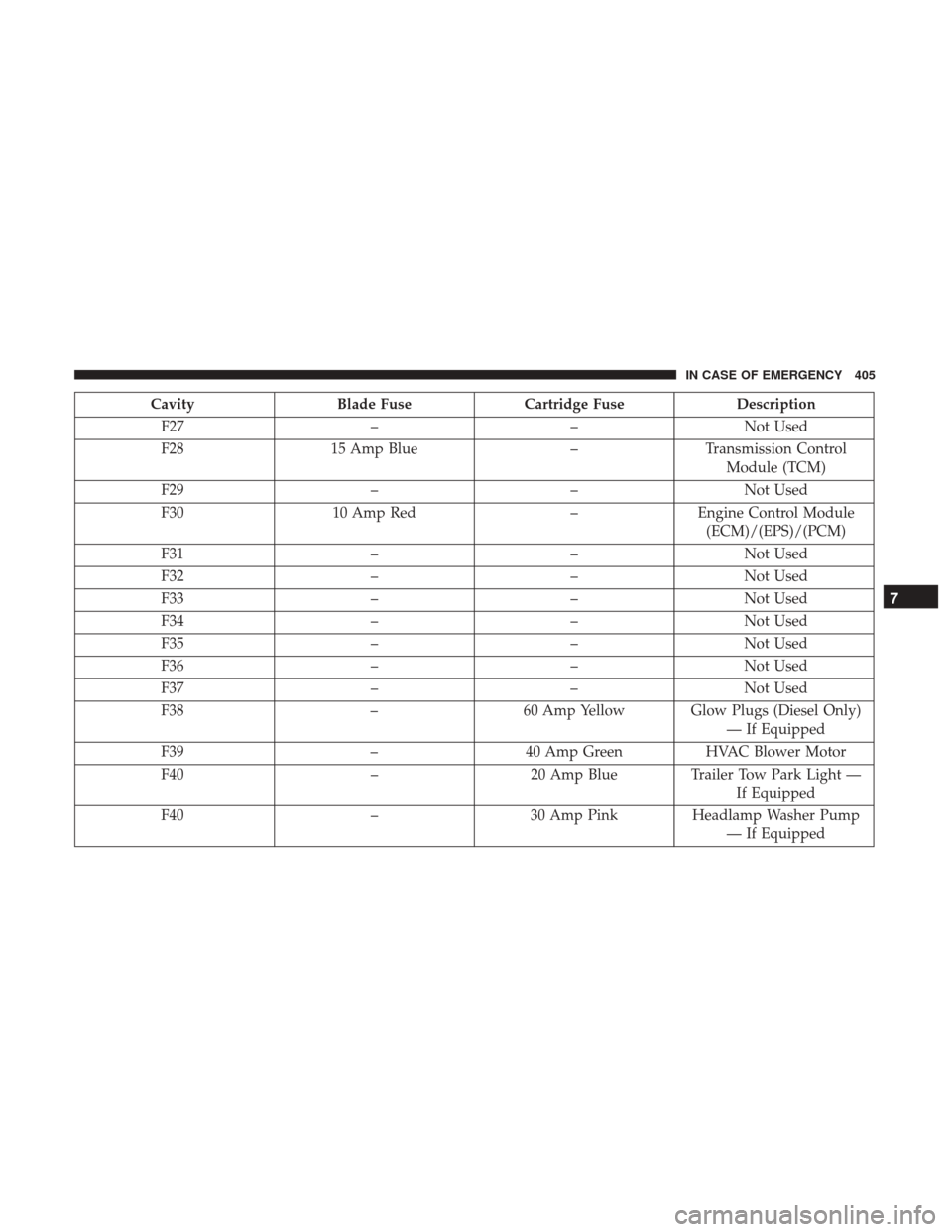
CavityBlade Fuse Cartridge Fuse Description
F27 ––Not Used
F28 15 Amp Blue –Transmission Control
Module (TCM)
F29 ––Not Used
F30 10 Amp Red –Engine Control Module
(ECM)/(EPS)/(PCM)
F31 ––Not Used
F32 ––Not Used
F33 ––Not Used
F34 ––Not Used
F35 ––Not Used
F36 ––Not Used
F37 ––Not Used
F38 –60 Amp Yellow Glow Plugs (Diesel Only)
— If Equipped
F39 –40 Amp Green HVAC Blower Motor
F40 –20 Amp Blue Trailer Tow Park Light —
If Equipped
F40 –30 Amp Pink Headlamp Washer Pump
— If Equipped
7
IN CASE OF EMERGENCY 405
Page 408 of 615
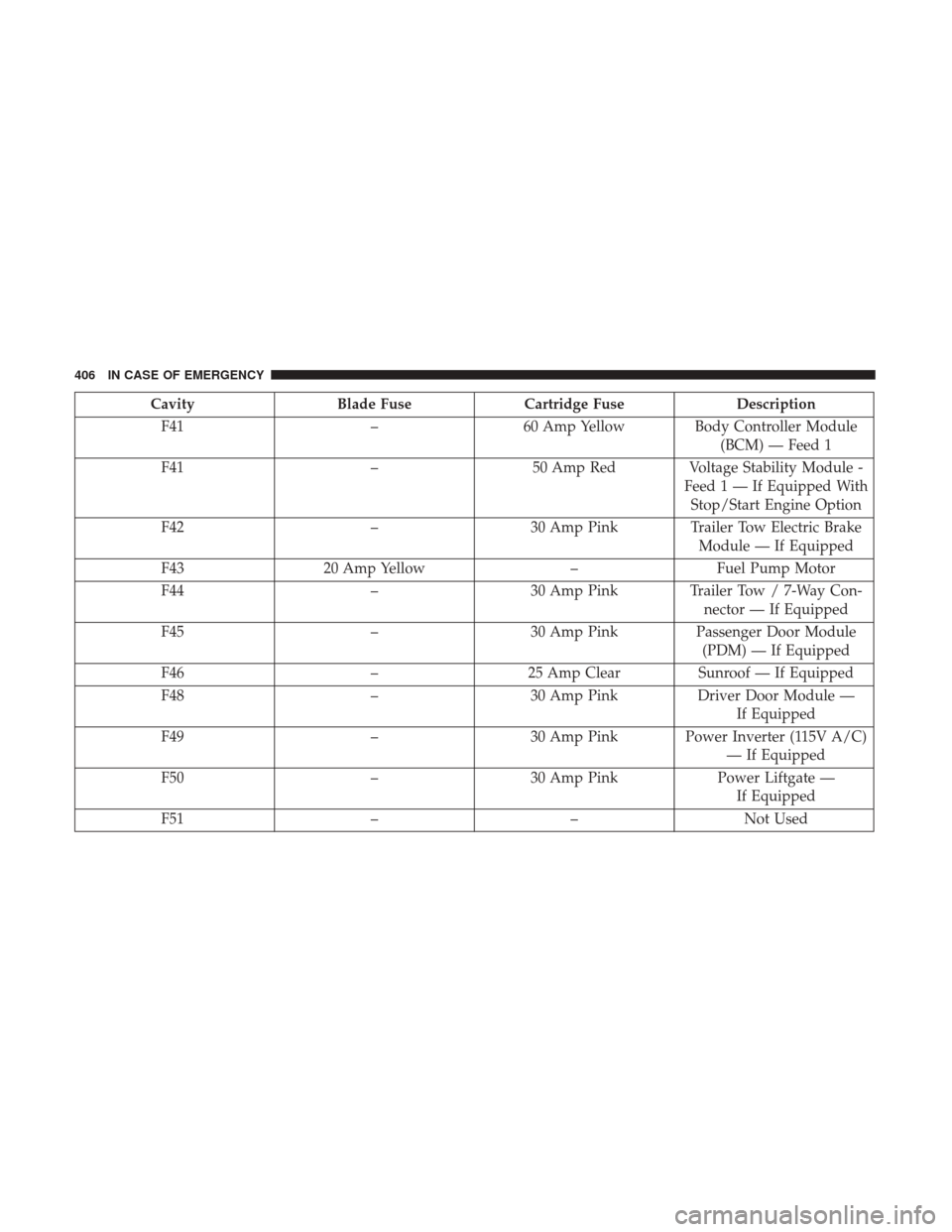
CavityBlade Fuse Cartridge Fuse Description
F41 –60 Amp Yellow Body Controller Module
(BCM) — Feed 1
F41 –50 Amp Red Voltage Stability Module -
Feed1—IfEquipped WithStop/Start Engine Option
F42 –30 Amp Pink Trailer Tow Electric Brake
Module — If Equipped
F43 20 Amp Yellow –Fuel Pump Motor
F44 –30 Amp Pink Trailer Tow / 7-Way Con-
nector — If Equipped
F45 –30 Amp Pink Passenger Door Module
(PDM) — If Equipped
F46 –25 Amp Clear Sunroof — If Equipped
F48 –30 Amp Pink Driver Door Module —
If Equipped
F49 –30 Amp Pink Power Inverter (115V A/C)
— If Equipped
F50 –30 Amp Pink Power Liftgate —
If Equipped
F51 ––Not Used
406 IN CASE OF EMERGENCY
Page 409 of 615
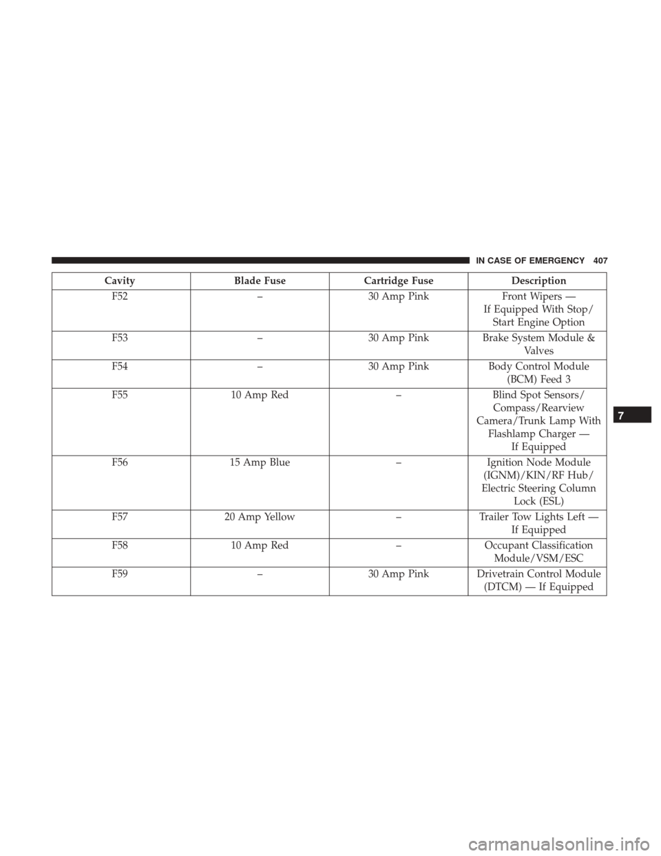
CavityBlade Fuse Cartridge Fuse Description
F52 –30 Amp Pink Front Wipers —
If Equipped With Stop/ Start Engine Option
F53 –30 Amp Pink Brake System Module &
Valves
F54 –30 Amp Pink Body Control Module
(BCM) Feed 3
F55 10 Amp Red –Blind Spot Sensors/
Compass/Rearview
Camera/Trunk Lamp With Flashlamp Charger — If Equipped
F56 15 Amp Blue –Ignition Node Module
(IGNM)/KIN/RF Hub/
Electric Steering Column Lock (ESL)
F57 20 Amp Yellow –Trailer Tow Lights Left —
If Equipped
F58 10 Amp Red –Occupant Classification
Module/VSM/ESC
F59 –30 Amp Pink Drivetrain Control Module
(DTCM) — If Equipped
7
IN CASE OF EMERGENCY 407
Page 410 of 615
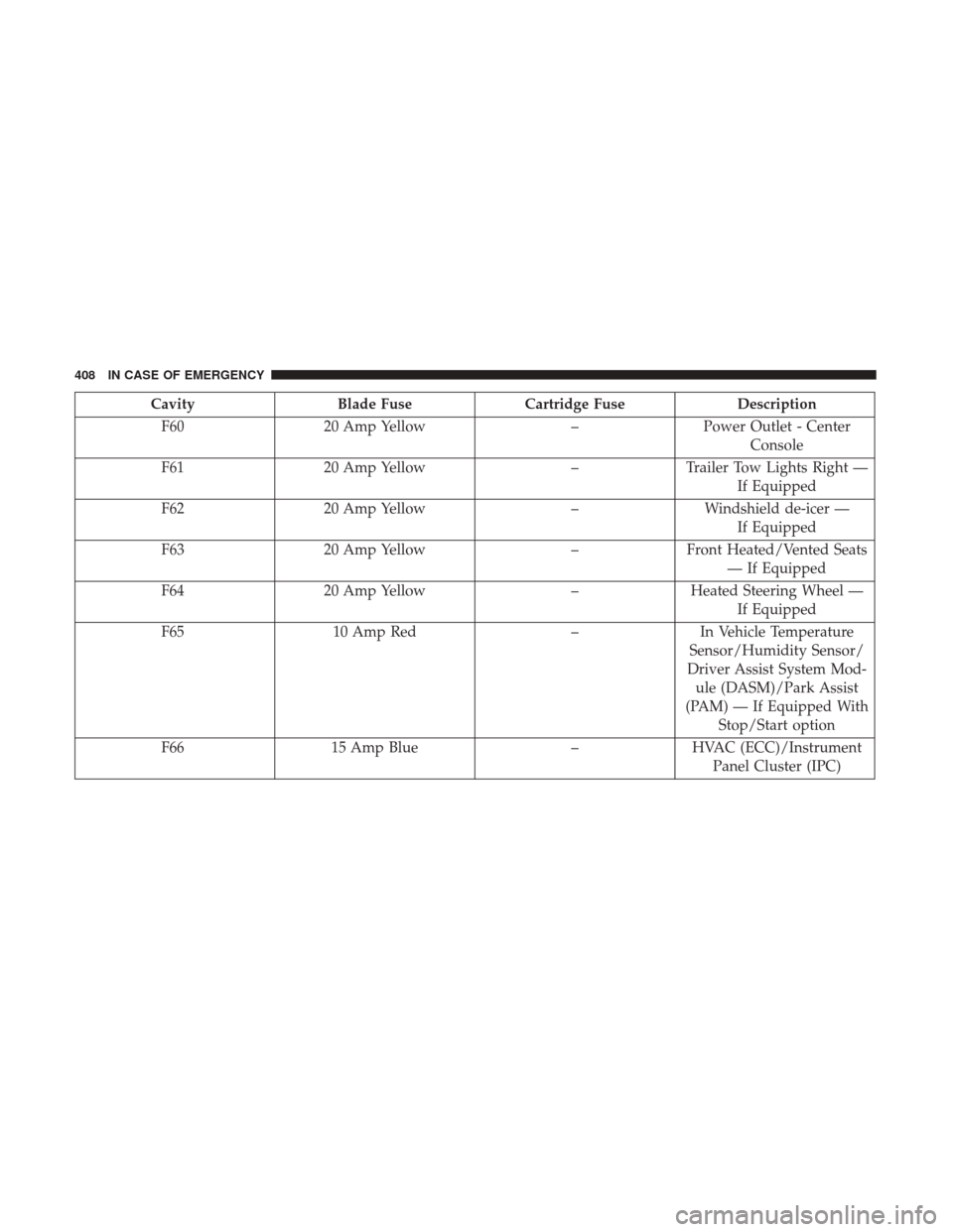
CavityBlade Fuse Cartridge Fuse Description
F60 20 Amp Yellow –Power Outlet - Center
Console
F61 20 Amp Yellow –Trailer Tow Lights Right —
If Equipped
F62 20 Amp Yellow –Windshield de-icer —
If Equipped
F63 20 Amp Yellow –Front Heated/Vented Seats
— If Equipped
F64 20 Amp Yellow –Heated Steering Wheel —
If Equipped
F65 10 Amp Red –In Vehicle Temperature
Sensor/Humidity Sensor/
Driver Assist System Mod- ule (DASM)/Park Assist
(PAM) — If Equipped With Stop/Start option
F66 15 Amp Blue –HVAC (ECC)/Instrument
Panel Cluster (IPC)
408 IN CASE OF EMERGENCY
Page 412 of 615
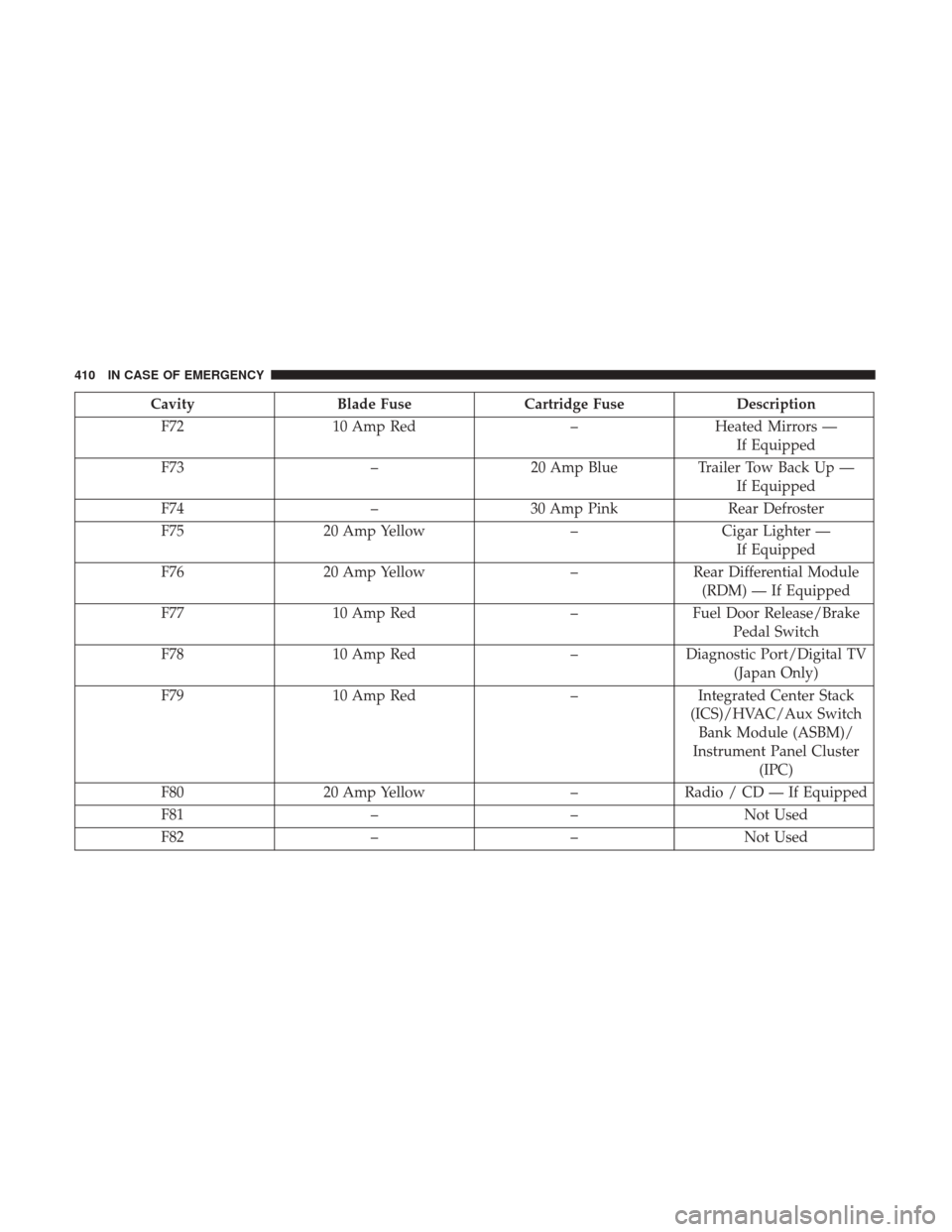
CavityBlade Fuse Cartridge Fuse Description
F72 10 Amp Red –Heated Mirrors —
If Equipped
F73 –20 Amp Blue Trailer Tow Back Up —
If Equipped
F74 –30 Amp Pink Rear Defroster
F75 20 Amp Yellow –Cigar Lighter —
If Equipped
F76 20 Amp Yellow –Rear Differential Module
(RDM) — If Equipped
F77 10 Amp Red –Fuel Door Release/Brake
Pedal Switch
F78 10 Amp Red –Diagnostic Port/Digital TV
(Japan Only)
F79 10 Amp Red –Integrated Center Stack
(ICS)/HVAC/Aux Switch Bank Module (ASBM)/
Instrument Panel Cluster (IPC)
F80 20 Amp Yellow –Radio / CD — If Equipped
F81 ––Not Used
F82 ––Not Used
410 IN CASE OF EMERGENCY
Page 416 of 615
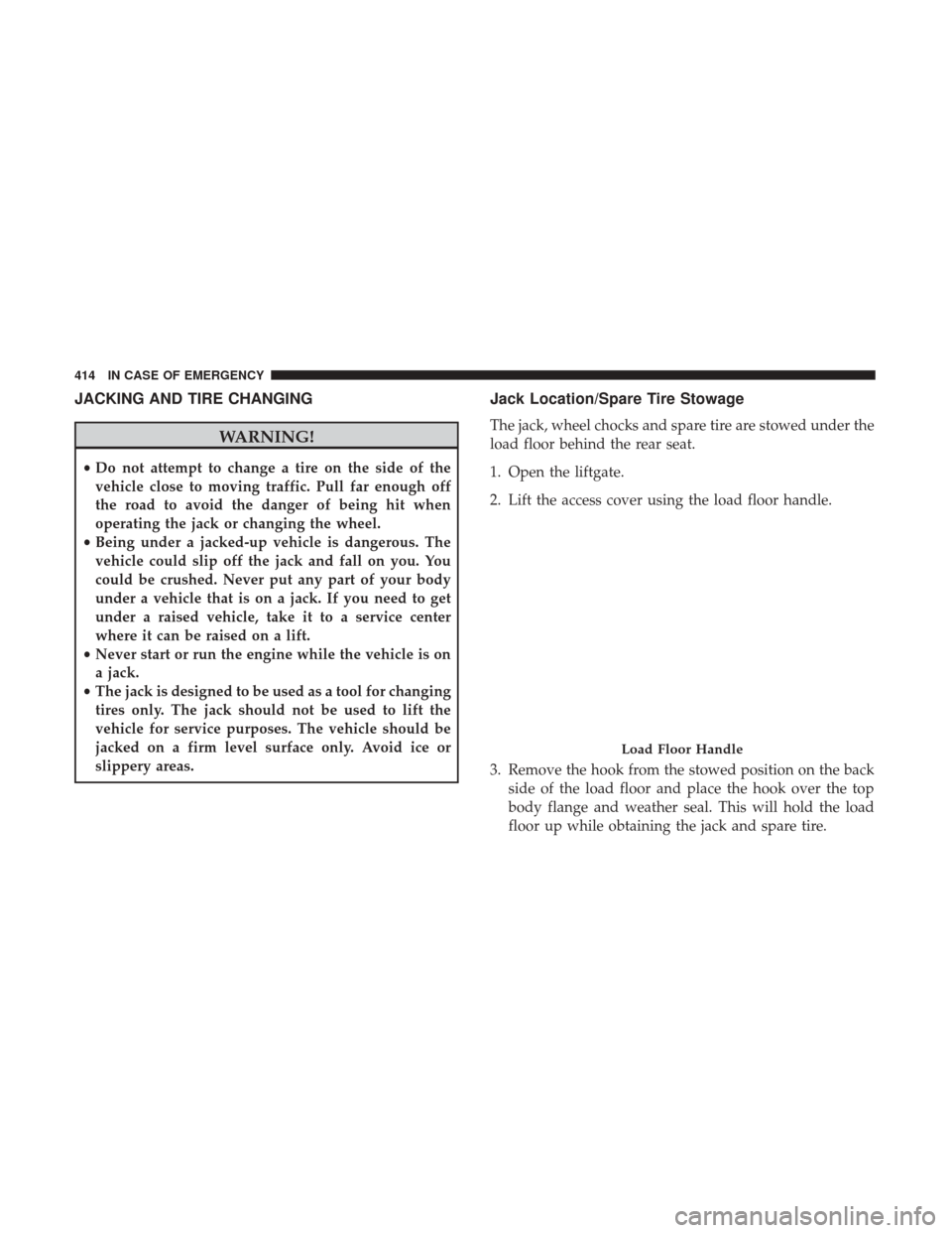
JACKING AND TIRE CHANGING
WARNING!
•Do not attempt to change a tire on the side of the
vehicle close to moving traffic. Pull far enough off
the road to avoid the danger of being hit when
operating the jack or changing the wheel.
• Being under a jacked-up vehicle is dangerous. The
vehicle could slip off the jack and fall on you. You
could be crushed. Never put any part of your body
under a vehicle that is on a jack. If you need to get
under a raised vehicle, take it to a service center
where it can be raised on a lift.
• Never start or run the engine while the vehicle is on
a jack.
• The jack is designed to be used as a tool for changing
tires only. The jack should not be used to lift the
vehicle for service purposes. The vehicle should be
jacked on a firm level surface only. Avoid ice or
slippery areas.
Jack Location/Spare Tire Stowage
The jack, wheel chocks and spare tire are stowed under the
load floor behind the rear seat.
1. Open the liftgate.
2. Lift the access cover using the load floor handle.
3. Remove the hook from the stowed position on the back side of the load floor and place the hook over the top
body flange and weather seal. This will hold the load
floor up while obtaining the jack and spare tire.
Load Floor Handle
414 IN CASE OF EMERGENCY
Page 418 of 615
WARNING!
A loose tire or jack thrown forward in a collision or
hard stop could endanger the occupants of the vehicle.
Always stow the jack parts and the spare tire in the
places provided. Have the deflated (flat) tire repaired
or replaced immediately.
Preparations For Jacking
1. Park the vehicle on a firm level surface as far from theedge of the roadway as possible. Avoid icy or slippery
areas.
WARNING!
Do not attempt to change a tire on the side of the
vehicle close to moving traffic, pull far enough off the
road to avoid being hit when operating the jack or
changing the wheel. 2. Turn on the Hazard Warning flasher.
3. Set the parking brake.
4. Place the gear selector into PARK.
5. Turn the ignition off to the LOCK position.
6. Chock both the front and rear of the wheel diagonally
opposite of the jacking position. For
example, if changing the right front
tire, chock the left rear wheel.
NOTE: Passengers should not remain in the vehicle when
the vehicle is being jacked.
416 IN CASE OF EMERGENCY
Page 419 of 615
Jacking Instructions
WARNING!
Carefully follow these tire changing warnings to help
prevent personal injury or damage to your vehicle:
•
Always park on a firm, level surface as far from the
edge of the roadway as possible before raising the
vehicle.
• Turn on the Hazard Warning flasher.
•
Chock the wheel diagonally opposite the wheel to be
raised.
•Set the parking brake firmly and set the transmission
in PARK.
•Never start or run the engine with the vehicle on a
jack.
•Do not let anyone sit in the vehicle when it is on a jack.
•Do not get under the vehicle when it is on a jack. If you
need to get under a raised vehicle, take it to a service
center where it can be raised on a lift.
•Only use the jack in the positions indicated and for
lifting this vehicle during a tire change.
•If working on or near a roadway, be extremely careful
of motor traffic.
(Continued)
WARNING! (Continued)
•To assure that spare tires, flat or inflated, are securely
stowed, spares must be stowed with the valve stem
facing the ground.
Jack Warning Label
7
IN CASE OF EMERGENCY 417