JEEP CHEROKEE 2018 Owner handbook (in English)
Manufacturer: JEEP, Model Year: 2018, Model line: CHEROKEE, Model: JEEP CHEROKEE 2018Pages: 312, PDF Size: 4.91 MB
Page 171 of 312
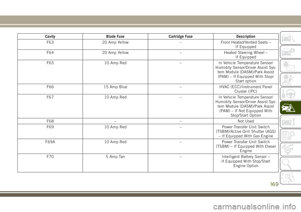
CavityBlade Fuse Cartridge Fuse Description
F63 20 Amp Yellow –Front Heated/Vented Seats –
If Equipped
F64 20 Amp Yellow –Heated Steering Wheel –
If Equipped
F65 10 Amp Red –In Vehicle Temperature Sensor/
Humidity Sensor/Driver Assist Sys- tem Module (DASM)/Park Assist(PAM) – If Equipped With Stop/ Start option
F66 15 Amp Blue –HVAC (ECC)/Instrument Panel
Cluster (IPC)
F67 10 Amp Red –In Vehicle Temperature Sensor/
Humidity Sensor/Driver Assist Sys- tem Module (DASM)/Park Assist(PAM) – If Not Equipped With Stop/Start Option
F68 ––Not Used
F69 10 Amp Red –Power Transfer Unit Switch
(TSBM)/Active Grill Shutter (AGS) – If Equipped With Gas Engine
F69A 10 Amp Red –Power Transfer Unit Switch
(TSBM) – If Equipped With Diesel Engine
F70 5 Amp Tan –Intelligent Battery Sensor –
If Equipped With Stop/Start Engine Option
169
Page 172 of 312
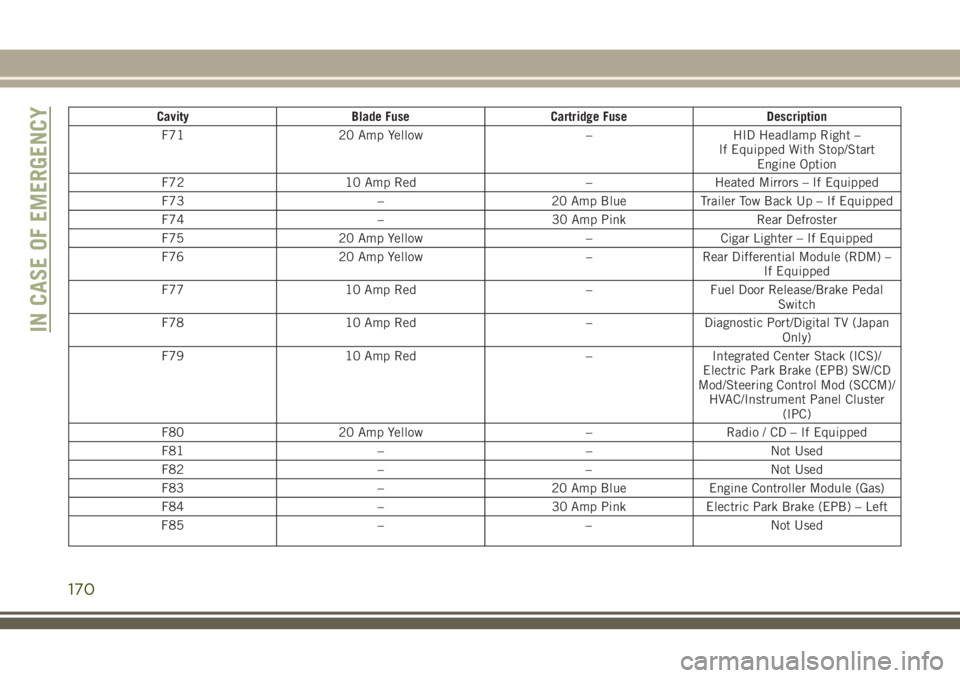
CavityBlade Fuse Cartridge Fuse Description
F71 20 Amp Yellow –HID Headlamp Right –
If Equipped With Stop/Start Engine Option
F72 10 Amp Red –Heated Mirrors – If Equipped
F73 –20 Amp BlueTrailer Tow Back Up – If Equipped
F74 –30 Amp Pink Rear Defroster
F75 20 Amp Yellow –Cigar Lighter – If Equipped
F76 20 Amp Yellow –Rear Differential Module (RDM) –
If Equipped
F77 10 Amp Red –Fuel Door Release/Brake Pedal
Switch
F78 10 Amp Red –Diagnostic Port/Digital TV (Japan
Only)
F79 10 Amp Red –Integrated Center Stack (ICS)/
Electric Park Brake (EPB) SW/CD
Mod/Steering Control Mod (SCCM)/ HVAC/Instrument Panel Cluster (IPC)
F80 20 Amp Yellow –Radio / CD – If Equipped
F81 ––Not Used
F82 ––Not Used
F83 –20 Amp BlueEngine Controller Module (Gas)
F84 –30 Amp PinkElectric Park Brake (EPB) – Left
F85 ––Not Used
IN CASE OF EMERGENCY
170
Page 173 of 312
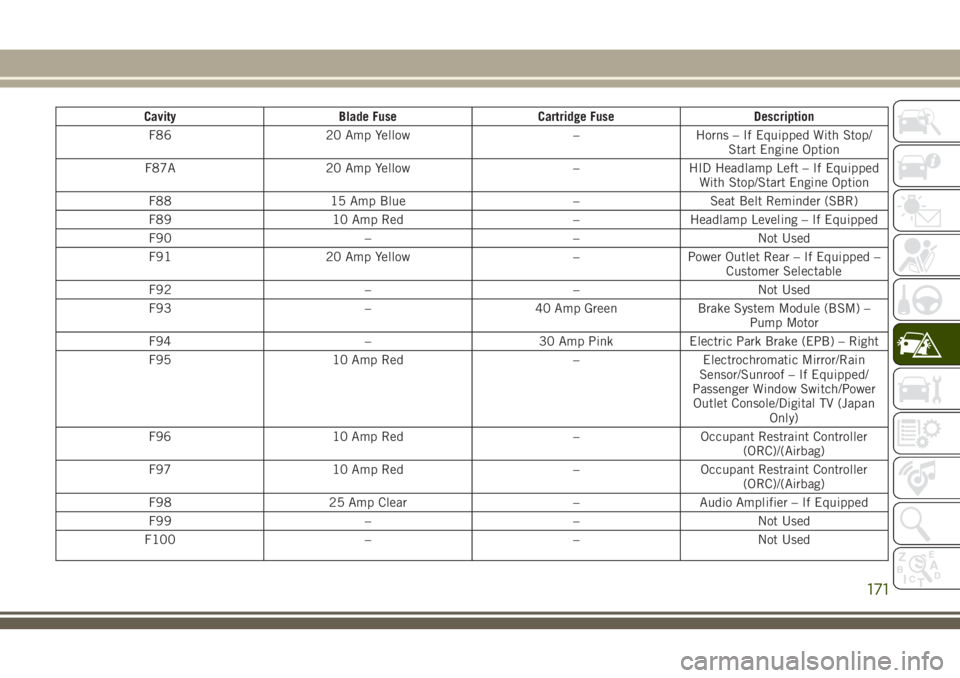
CavityBlade Fuse Cartridge Fuse Description
F86 20 Amp Yellow –Horns – If Equipped With Stop/
Start Engine Option
F87A 20 Amp Yellow –HID Headlamp Left – If Equipped
With Stop/Start Engine Option
F88 15 Amp Blue –Seat Belt Reminder (SBR)
F89 10 Amp Red –Headlamp Leveling – If Equipped
F90 ––Not Used
F91 20 Amp Yellow –Power Outlet Rear – If Equipped –
Customer Selectable
F92 ––Not Used
F93 –40 Amp GreenBrake System Module (BSM) –
Pump Motor
F94 –30 Amp PinkElectric Park Brake (EPB) – Right
F95 10 Amp Red –Electrochromatic Mirror/Rain
Sensor/Sunroof – If Equipped/
Passenger Window Switch/Power Outlet Console/Digital TV (Japan Only)
F96 10 Amp Red –Occupant Restraint Controller
(ORC)/(Airbag)
F97 10 Amp Red –Occupant Restraint Controller
(ORC)/(Airbag)
F98 25 Amp Clear –Audio Amplifier – If Equipped
F99 ––Not Used
F100 ––Not Used
171
Page 174 of 312
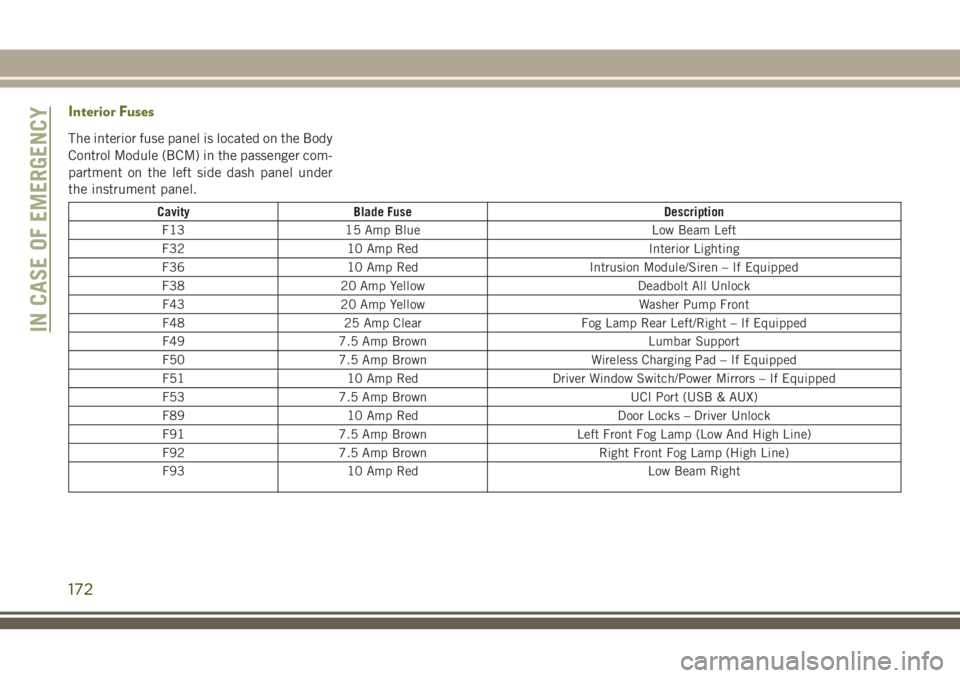
Interior Fuses
The interior fuse panel is located on the Body
Control Module (BCM) in the passenger com-
partment on the left side dash panel under
the instrument panel.
CavityBlade Fuse Description
F13 15 Amp Blue Low Beam Left
F32 10 Amp Red Interior Lighting
F36 10 Amp Red Intrusion Module/Siren – If Equipped
F38 20 Amp Yellow Deadbolt All Unlock
F43 20 Amp Yellow Washer Pump Front
F48 25 Amp Clear Fog Lamp Rear Left/Right – If Equipped
F49 7.5 Amp Brown Lumbar Support
F50 7.5 Amp Brown Wireless Charging Pad – If Equipped
F51 10 Amp Red Driver Window Switch/Power Mirrors – If Equipped
F53 7.5 Amp Brown UCI Port (USB & AUX)
F89 10 Amp Red Door Locks – Driver Unlock
F91 7.5 Amp Brown Left Front Fog Lamp (Low And High Line)
F92 7.5 Amp Brown Right Front Fog Lamp (High Line)
F93 10 Amp Red Low Beam Right
IN CASE OF EMERGENCY
172
Page 175 of 312
JACKING AND TIRE
CHANGING
WARNING!
• Do not attempt to change a tire on theside of the vehicle close to moving traf-
fic. Pull far enough off the road to avoid
the danger of being hit when operating
the jack or changing the wheel.
• Being under a jacked-up vehicle is dan-
gerous. The vehicle could slip off the
jack and fall on you. You could be
crushed. Never put any part of your body
under a vehicle that is on a jack. If you
need to get under a raised vehicle, take
it to a service center where it can be
raised on a lift.
• Never start or run the engine while the
vehicle is on a jack.
• The jack is designed to be used as a tool
for changing tires only. The jack should
not be used to lift the vehicle for service
purposes. The vehicle should be jacked
on a firm level surface only. Avoid ice or
slippery areas.
Jack Location/Spare Tire Stowage
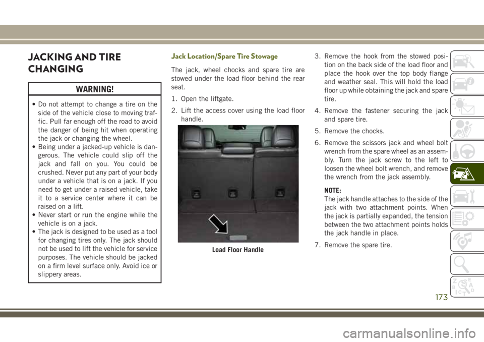
The jack, wheel chocks and spare tire are
stowed under the load floor behind the rear
seat.
1. Open the liftgate.
2. Lift the access cover using the load floor handle. 3. Remove the hook from the stowed posi-
tion on the back side of the load floor and
place the hook over the top body flange
and weather seal. This will hold the load
floor up while obtaining the jack and spare
tire.
4. Remove the fastener securing the jack and spare tire.
5. Remove the chocks.
6. Remove the scissors jack and wheel bolt wrench from the spare wheel as an assem-
bly. Turn the jack screw to the left to
loosen the wheel bolt wrench, and remove
the wrench from the jack assembly.
NOTE:
The jack handle attaches to the side of the
jack with two attachment points. When
the jack is partially expanded, the tension
between the two attachment points holds
the jack handle in place.
7. Remove the spare tire.
Load Floor Handle
173
Page 176 of 312
WARNING!
A loose tire or jack thrown forward in a
collision or hard stop could endanger the
occupants of the vehicle. Always stow the
jack parts and the spare tire in the places
provided. Have the deflated (flat) tire re-
paired or replaced immediately.
Preparations For Jacking
1. Park the vehicle on a firm level surface asfar from the edge of the roadway as pos-
sible. Avoid icy or slippery areas.
WARNING!
Do not attempt to change a tire on the side
of the vehicle close to moving traffic. Pull
far enough off the road to avoid being hit
when operating the jack or changing the
wheel.
2. Turn on the Hazard Warning flasher.
3. Apply the parking brake.
4. Place the gear selector into PARK (auto- matic transmission) or REVERSE (manual
transmission). 5. Turn the ignition off to the LOCK position.
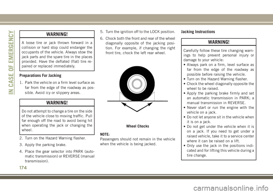
6. Chock both the front and rear of the wheel
diagonally opposite of the jacking posi-
tion. For example, if changing the right
front tire, chock the left rear wheel.
NOTE:
Passengers should not remain in the vehicle
when the vehicle is being jacked.
Jacking Instructions
WARNING!
Carefully follow these tire changing warn-
ings to help prevent personal injury or
damage to your vehicle:
• Always park on a firm, level surface as far from the edge of the roadway as
possible before raising the vehicle.
• Turn on the Hazard Warning flasher.
• Chock the wheel diagonally opposite the
wheel to be raised.
• Apply the parking brake firmly and set
an automatic transmission in PARK; a
manual transmission in REVERSE.
• Never start or run the engine with the
vehicle on a jack.
• Do not let anyone sit in the vehicle when
it is on a jack.
• Do not get under the vehicle when it is
on a jack. If you need to get under a
raised vehicle, take it to a service center
where it can be raised on a lift.
• Only use the jack in the positions indi-
cated and for lifting this vehicle during a
tire change.
Wheel Chocks
IN CASE OF EMERGENCY
174
Page 177 of 312
WARNING!
• If working on or near a roadway, beextremely careful of motor traffic.
• To assure that spare tires, flat or in-
flated, are securely stowed, spares must
be stowed with the valve stem facing the
ground.
CAUTION!
Do not attempt to raise the vehicle by
jacking on locations other than those indi-
cated in the Jacking Instructions for this
vehicle.
1. Remove the spare tire, jack, and wheel bolt wrench.
2. If equipped with aluminum wheels where the center cap covers the wheel bolts, use
the wheel bolt wrench to pry the center
cap off carefully before raising the
vehicle.
3. Before raising the vehicle, use the wheel bolt wrench to loosen, but not remove, the
wheel bolts on the wheel with the flat tire.
Turn the wheel bolts counterclockwise one
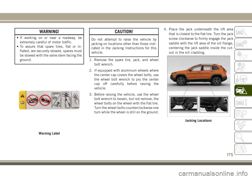
turn while the wheel is still on the ground. 4. Place the jack underneath the lift area
that is closest to the flat tire. Turn the jack
screw clockwise to firmly engage the jack
saddle with the lift area of the sill flange,
centering the jack saddle inside the cut-
out in the sill cladding.
Warning Label
Jacking Locations
175
Page 178 of 312
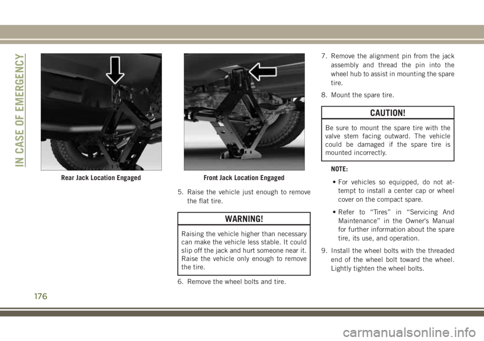
5. Raise the vehicle just enough to removethe flat tire.
WARNING!
Raising the vehicle higher than necessary
can make the vehicle less stable. It could
slip off the jack and hurt someone near it.
Raise the vehicle only enough to remove
the tire.
6. Remove the wheel bolts and tire. 7. Remove the alignment pin from the jack
assembly and thread the pin into the
wheel hub to assist in mounting the spare
tire.
8. Mount the spare tire.
CAUTION!
Be sure to mount the spare tire with the
valve stem facing outward. The vehicle
could be damaged if the spare tire is
mounted incorrectly.
NOTE:• For vehicles so equipped, do not at- tempt to install a center cap or wheel
cover on the compact spare.
• Refer to “Tires” in “Servicing And Maintenance” in the Owner's Manual
for further information about the spare
tire, its use, and operation.
9. Install the wheel bolts with the threaded end of the wheel bolt toward the wheel.
Lightly tighten the wheel bolts.
Rear Jack Location EngagedFront Jack Location Engaged
IN CASE OF EMERGENCY
176
Page 179 of 312
WARNING!
To avoid the risk of forcing the vehicle off
the jack, do not tighten the wheel nuts
fully until the vehicle has been lowered.
Failure to follow this warning may result in
serious injury.
10. Lower the vehicle to the ground by turn- ing the jack handle counterclockwise.
11. Finish tightening the wheel bolts. Push down on the wrench while at the end of
the handle for increased leverage.
Tighten the wheel bolts in a star pattern
until each wheel bolt has been tightened
twice. Refer to “Torque Specifications”
in “Technical Specifications” for the
proper lug bolt torque. If in doubt about
the correct tightness, have them
checked with a torque wrench by your
authorized dealer or at a service station.
12. Securely stow the jack, tools, chocks, and flat tire.
WARNING!
A loose tire or jack thrown forward in a
collision or hard stop could endanger the
occupants of the vehicle. Always stow the
jack parts and the spare tire in the places
provided. Have the deflated (flat) tire re-
paired or replaced immediately.
Changing Procedure
1. Mount the road tire on the axle.
2. Install the remaining wheel bolts with thethreaded end of the wheel bolt toward the
wheel. Lightly tighten the wheel bolts.
WARNING!
To avoid the risk of forcing the vehicle off
the jack, do not tighten the wheel nuts
fully until the vehicle has been lowered.
Failure to follow this warning may result in
serious injury. 3. Lower the vehicle to the ground by turning
the jack handle counterclockwise.
4. Finish tightening the wheel bolts. Push down on the wrench while at the end of
the handle for increased leverage. Tighten
the wheel bolts in a star pattern until each
wheel bolt has been tightened twice. Re-
fer to “Torque Specifications” in “Techni-
cal Specifications” for the proper lug bolt
torque. If in doubt about the correct tight-
ness, have them checked with a torque
wrench by your authorized dealer or ser-
vice station.
5. Lower the jack until it is free. Remove the wheel chocks. Reassemble the lug wrench
to the jack assembly and stow it in the
spare tire area. Secure the assembly using
the means provided. Release the parking
brake before driving the vehicle.
6. After 25 miles (40 km) check the wheel bolt torque with a torque wrench to ensure
that all wheel bolts are properly seated
against the wheel.
177
Page 180 of 312
Declaration Of Conformance
1. The undersigned, Tony Fabiano, repre-senting the manufacturer, herewith de-
clares that the machinery described be-
low fulfills all relevant provisions of:
• The EC-directive 2006/42/EC on Machinery
2. Description of machinery. a) Generic Denomination: Vehicle Jack
b) Function: Lifting Vehicle
d) Ve-hicle
Model c) Model
Code f) Work-
ing Load e) Jack
Type
Jeep
®
Compass MK 1200 kg
MaxFGMF1
Jeep
Cherokee KL 1000 kg
MaxFGLF1
Jeep
Wrangler JK 1000 kg
MaxFGLF2
Jeep
Grand
Cherokee WK 1700 kg
MaxFGLF3
3. Manufacturers (1):
FlexNGate Seeburn, a division of Ventra
Group Co
P.O. Box 1170, 65 Industrial Road, Totten-
ham, ON CANADA L0G 1W0
4. Manufacturers (2): FlexNGate Querétaro Ventramex, S.A. de
C.V
Av. Manantiales No. 3
Parque Industrial Bernardo Quintana, El
Marqués Querétaro C.P. 76249 – Mexico
5. Legal Person authorized to compile the technical file:
FlexNGate – Barcelona
Avda de la Riera, 7-9
Sant Just Desvern, Barcelona, SPAIN 08960 6. References to harmonized standards:
PF-12074
7. Done at: Bradford, ON CANADA
8. Date: 09/30/2015
IN CASE OF EMERGENCY
178