JEEP CHEROKEE 2018 Owner handbook (in English)
Manufacturer: JEEP, Model Year: 2018, Model line: CHEROKEE, Model: JEEP CHEROKEE 2018Pages: 312, PDF Size: 4.91 MB
Page 161 of 312
IN CASE OF EMERGENCY
HAZARD WARNING
FLASHERS................160
Control....................160
BULB REPLACEMENT ........160
Replacement Bulbs.............160
Replacing Exterior Bulbs ..........161
FUSES....................164
General Information .............164
Underhood Fuses ..............164
Interior Fuses ................172
JACKING AND TIRE
CHANGING................173
Jack Location/Spare Tire Stowage . . . .173
Changing Procedure ............177 Declaration Of Conformance
.......178
Jack Usage Precautions ..........180
TIRE SERVICE KIT —
IF EQUIPPED...............180
Tire Service Kit Storage ..........180
Tire Service Kit Components And
Operation ...................181
Tire Service Kit Usage Precautions . . . .181
Sealing A Tire With Tire Service Kit . . .182
JUMP STARTING ............186
Preparations For Jump Start ........186
Jump Starting Procedure ..........187
REFUELING IN EMERGENCY . . . .188
Emergency Fuel Filler Door Release . . .188
IF YOUR ENGINE OVERHEATS . .188
GEAR SELECTOR OVERRIDE . . .189
FREEING A STUCK VEHICLE. . . .189
TOWING A DISABLED
VEHICLE..................190
Without The Key Fob ............191
Front-Wheel Drive (FWD) Models —
WithKeyFob.................191
4x4 Models ..................192
Recovery Strap — If Equipped ......192
ENHANCED ACCIDENT
RESPONSE SYSTEM (EARS) . . . .193
EVENT DATA RECORDER
(EDR)....................193
IN CASE OF EMERGENCY
159
Page 162 of 312
HAZARD WARNING
FLASHERS
Control
The Hazard Warning flasher switch is located
on the switch bank just above the climate
controls.
Push the switch to turn on the Hazard Warn-
ing flasher. When the switch is activated, all
directional turn signals will flash on and off towarn oncoming traffic of an emergency. Push
the switch a second time to turn off the
Hazard Warning flashers.
This is an emergency warning system and it
should not be used when the vehicle is in
motion. Use it when your vehicle is disabled
and it is creating a safety hazard for other
motorists.
When you must leave the vehicle to seek
assistance, the Hazard Warning flashers will
continue to operate even though the ignition
is placed in the OFF position. NOTE:
With extended use, the Hazard Warning
flashers may discharge the battery.
BULB REPLACEMENT
Replacement Bulbs
Interior Bulbs
Bulb Number
Cargo Lamp TL212–2
Overhead Console Lamp PLW214–2A Reading Lamp WL212–2
IN CASE OF EMERGENCY
160
Page 163 of 312
Exterior Bulbs
Bulb Number
Low Beam/High Beam (Bi-Halogen) Headlamps 9005HL + Low Beam/High Beam (Bi-Xenon) Headlamps D3S (Serviced at an authorized dealer) Front Park/Daytime Running Lamps LED (Serviced at an authorized dealer)
Front Turn Signal Lamps WY21WFront Fog Lamps PSX24W
Rear Tail/Stop Lamps LED (Serviced at an authorized dealer)
Rear Turn Signal Lamps WY21W
Center High Mounted Stop Lamp (CHMSL) LED (Serviced at an authorized dealer) Back-Up Lamps W16W or 921
License Plate Lamp W5W Rear Fog Lamps W21W
Replacing Exterior Bulbs
Bi-Xenon High Intensity Discharge (HID)
Headlamps — If Equipped
The headlamps contain a type of high voltage
discharge light source. High voltage can re-
main in the circuit even with the headlamp
switch off. Because of this, you should not
attempt to service a HID headlamp light source yourself. If an HID headlamp light
source fails, take your vehicle to an autho-
rized dealer for service.
NOTE:
On vehicles equipped with HID headlamps,
when the headlamps are turned on, there is a
blue hue to the lights. This diminishes and
becomes more white after approximately
10 seconds, as the system charges.
WARNING!
A transient high voltage occurs at the bulb
sockets of HID headlamps when the head-
lamp switch is turned ON. It may cause
serious electrical shock or electrocution if
not serviced properly. See your authorized
dealer for service.
161
Page 164 of 312
Bi-Halogen Headlamps
1. Remove the three hex head screws fromthe wheel liner.
2. Pull the exterior edge of the liner towards the tire to gain access to the headlamp
bulb cap.
3. Firmly grasp the cap and rotate it counter- clockwise to unlock it.
4. Firmly grasp the bulb and connector as- sembly and rotate counterclockwise to
remove from the housing.
5. Disconnect the bulb from the electrical connector and then connect the replace-
ment bulb.
CAUTION!
Do not touch the new bulb with your fin-
gers. Oil contamination will severely
shorten bulb life. If the bulb comes in
contact with any oily surface, clean the
bulb with rubbing alcohol.
6. Install the bulb and connector assembly into the headlamp housing and rotate
clockwise to lock it in place. 7. Install the bulb cap in the headlamp
housing and rotate clockwise to lock it in
place.
8. Install the three hex head screws into the wheel liner.
Front Turn Signals And Front Side Marker
Lamps
1. Open the hood.
NOTE:
Removal of the air cleaner filter housing
may be necessary prior to replacing bulbs
in the upper lamp assembly on the pas-
senger side of the vehicle.
2. Twist the appropriate bulb and socket assembly counterclockwise, and then re-
move the bulb and socket assembly from
the lamp housing.
3. Pull the bulb out of the socket and insert the replacement bulb.
4. Install the bulb and socket assembly into the housing, and rotate the socket clock-
wise to lock it in place.
5. Re-install air cleaner filter housing if removed.
Front Fog Lamp
1. Remove the three hex head screws from
the wheel liner.
2. Pull the exterior edge of the wheel liner towards the tire to gain access to the bulb.
3. Squeeze the two tabs on the side of the bulb socket and pull straight out from the
fog lamp.
4. Disconnect the wire harness from the bulb.
CAUTION!
Do not touch the new bulb with your fin-
gers. Oil contamination will severely
shorten bulb life. If the bulb comes in
contact with any oily surface, clean the
bulb with rubbing alcohol.
5. Reconnect the wiring harness to the new bulb and reinstall by inserting the new
bulb straight into the fog lamp housing
until it locks in place.
6. Lock the lower door in the wheel liner.
IN CASE OF EMERGENCY
162
Page 165 of 312
Bodyside Mounted Back-Up Lamp
1. Open the liftgate.
2. Remove the screws that fasten the body-side mounted lamp housing to the
vehicle.
3. Grasp the tail lamp and pull firmly rear- ward to disengage the lamp from the
vehicle.
4. Disconnect the electrical connector.
5. Twist the socket counterclockwise and re- move from housing.
6. Pull the bulb to remove it from the socket.
7. Replace the bulb and install the socket.
8. Reconnect the electrical connector.
9. Reinstall the bodyside lamp housing and screws.
10. Close the liftgate.
Liftgate Mounted Back-up Lamp
1. Open the liftgate. 2. Use a fiber stick or flat blade screw driver
to pry the lower trim from the liftgate.
3. Once the trim is loose, pull it back expos- ing the trim panel.
4. Using a fiber stick or flat blade screw driver, open the trim panel exposing the
back of the liftgate lamp.
5. Disconnect the electrical connector.
6. Twist the socket counterclockwise and re- move from lamp.
7. Pull the bulb to remove it from the socket.
8. Replace the bulb, reinstall the socket.
9. Connect the electrical connector.
10. Reinstall the trim panel and the lower trim.
11. Close the liftgate.
License Plate Lamp
1. Using a small screwdriver, press inward the locking tab on the side of the lamp
assembly and pull down on the lamp as-
sembly for removal. 2. Pull bulb from socket, replace, and rein-
stall the lamp assembly into place ensur-
ing the locking tab is secure.
Rear Fog Lamp
1. Using a small screwdriver or fiber stick,press the locking tab on the reflex side of
the lamp and pull the lamp assembly out
for removal.
2. Disconnect the electrical connector.
3. Twist the socket counterclockwise and re- move from lamp.
4. Pull the bulb to remove it from the socket.
5. Replace the bulb and twist the socket clockwise to reinstall.
6. Connect the electrical connector.
7. Reinstall the lamp by sliding the hook on the fog lamp side over the locking tab in
the bumper opening and pushing the re-
flex side into the bumper to snap the lamp
assembly back into place.
163
Page 166 of 312
FUSES
WARNING!
• When replacing a blown fuse, always usean appropriate replacement fuse with
the same amp rating as the original fuse.
Never replace a fuse with another fuse of
higher amp rating. Never replace a
blown fuse with metal wires or any other
material. Do not place a fuse inside a
circuit breaker cavity or vice versa. Fail-
ure to use proper fuses may result in
serious personal injury, fire and/or prop-
erty damage.
• Before replacing a fuse, make sure that
the ignition is off and that all the other
services are switched off and/or disen-
gaged.
• If the replaced fuse blows again, contact
an authorized dealer.
WARNING!
• If a general protection fuse for safetysystems (air bag system, braking sys-
tem), power unit systems (engine sys-
tem, transmission system) or steering
system blows, contact an authorized
dealer.
General Information
The fuses protect electrical systems against
excessive current.
When a device does not work, you must check
the fuse element inside the blade fuse for a
break/melt.
Also, please be aware that when using power
outlets for extended periods of time with the
engine off may result in vehicle battery dis-
charge.
Underhood Fuses
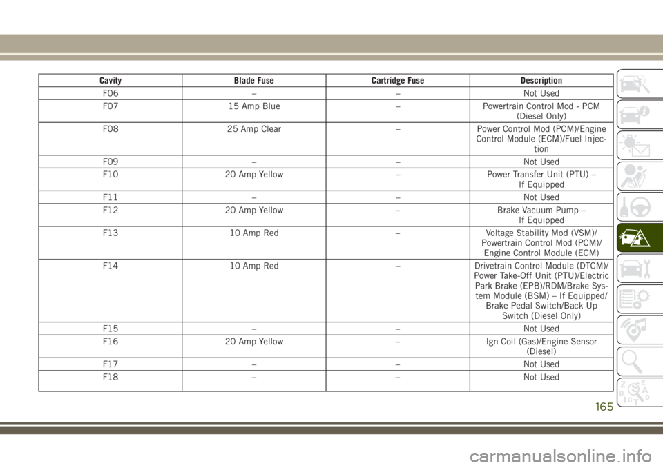
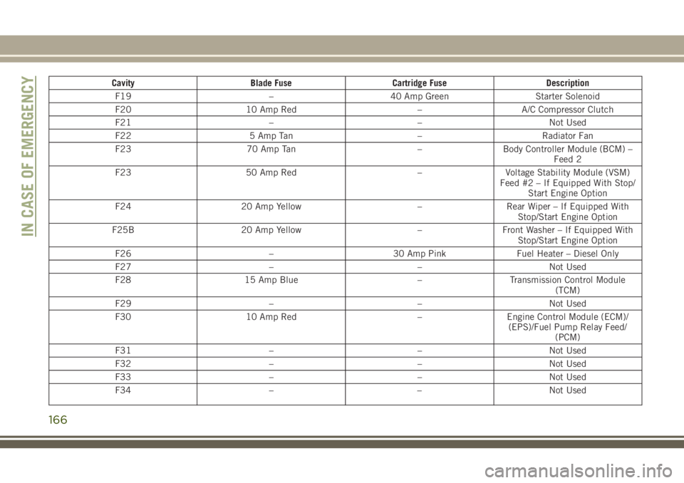
The Power Distribution Center is located in
the engine compartment near the battery.
This center contains cartridge fuses, mini-
fuses and relays. A label that identifies each
component is printed on the inside of the
cover.
IN CASE OF EMERGENCY
164
Page 167 of 312
CavityBlade Fuse Cartridge Fuse Description
F06 ––Not Used
F07 15 Amp Blue –Powertrain Control Mod - PCM
(Diesel Only)
F08 25 Amp Clear –Power Control Mod (PCM)/Engine
Control Module (ECM)/Fuel Injec- tion
F09 ––Not Used
F10 20 Amp Yellow –Power Transfer Unit (PTU) –
If Equipped
F11 ––Not Used
F12 20 Amp Yellow –Brake Vacuum Pump –
If Equipped
F13 10 Amp Red –Voltage Stability Mod (VSM)/
Powertrain Control Mod (PCM)/ Engine Control Module (ECM)
F14 10 Amp Red –Drivetrain Control Module (DTCM)/
Power Take-Off Unit (PTU)/Electric Park Brake (EPB)/RDM/Brake Sys-tem Module (BSM) – If Equipped/ Brake Pedal Switch/Back Up Switch (Diesel Only)
F15 ––Not Used
F16 20 Amp Yellow –Ign Coil (Gas)/Engine Sensor
(Diesel)
F17 ––Not Used
F18 ––Not Used
165
Page 168 of 312
CavityBlade Fuse Cartridge Fuse Description
F19 –40 Amp Green Starter Solenoid
F20 10 Amp Red –A/C Compressor Clutch
F21 ––Not Used
F22 5 Amp Tan –Radiator Fan
F23 70 Amp Tan –Body Controller Module (BCM) –
Feed 2
F23 50 Amp Red –Voltage Stability Module (VSM)
Feed #2 – If Equipped With Stop/ Start Engine Option
F24 20 Amp Yellow –Rear Wiper – If Equipped With
Stop/Start Engine Option
F25B 20 Amp Yellow –Front Washer – If Equipped With
Stop/Start Engine Option
F26 –30 Amp PinkFuel Heater – Diesel Only
F27 ––Not Used
F28 15 Amp Blue –Transmission Control Module
(TCM)
F29 ––Not Used
F30 10 Amp Red –Engine Control Module (ECM)/
(EPS)/Fuel Pump Relay Feed/ (PCM)
F31 ––Not Used
F32 ––Not Used
F33 ––Not Used
F34 ––Not Used
IN CASE OF EMERGENCY
166
Page 169 of 312
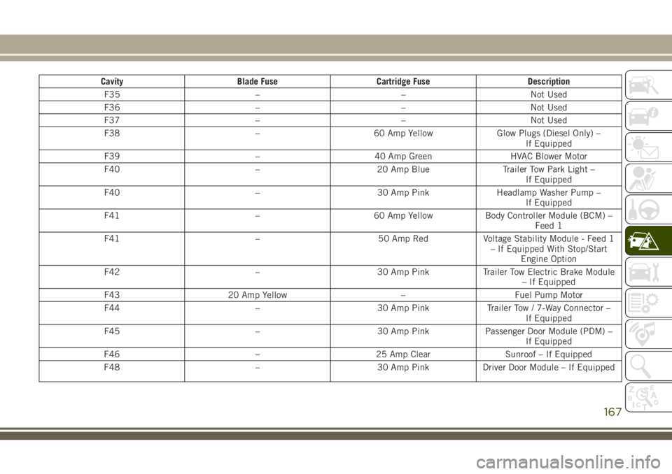
CavityBlade Fuse Cartridge Fuse Description
F35 ––Not Used
F36 ––Not Used
F37 ––Not Used
F38 –60 Amp Yellow Glow Plugs (Diesel Only) –
If Equipped
F39 –40 Amp Green HVAC Blower Motor
F40 –20 Amp Blue Trailer Tow Park Light –
If Equipped
F40 –30 Amp PinkHeadlamp Washer Pump –
If Equipped
F41 –60 Amp YellowBody Controller Module (BCM) –
Feed 1
F41 –50 Amp RedVoltage Stability Module - Feed 1
– If Equipped With Stop/Start Engine Option
F42 –30 Amp PinkTrailer Tow Electric Brake Module
– If Equipped
F43 20 Amp Yellow –Fuel Pump Motor
F44 –30 Amp PinkTrailer Tow / 7-Way Connector –
If Equipped
F45 –30 Amp PinkPassenger Door Module (PDM) –
If Equipped
F46 –25 Amp Clear Sunroof – If Equipped
F48 –30 Amp PinkDriver Door Module – If Equipped
167
Page 170 of 312
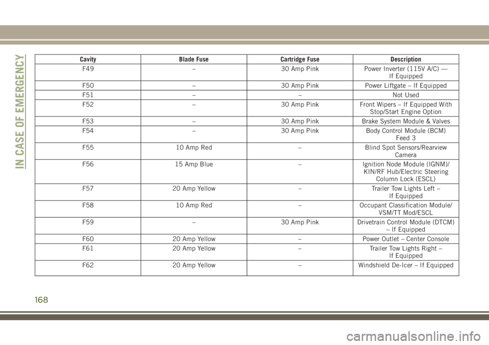
CavityBlade Fuse Cartridge Fuse Description
F49 –30 Amp PinkPower Inverter (115V A/C) —
If Equipped
F50 –30 Amp PinkPower Liftgate – If Equipped
F51 ––Not Used
F52 –30 Amp PinkFront Wipers – If Equipped With
Stop/Start Engine Option
F53 –30 Amp PinkBrake System Module & Valves
F54 –30 Amp PinkBody Control Module (BCM)
Feed 3
F55 10 Amp Red –Blind Spot Sensors/Rearview
Camera
F56 15 Amp Blue –Ignition Node Module (IGNM)/
KIN/RF Hub/Electric Steering Column Lock (ESCL)
F57 20 Amp Yellow –Trailer Tow Lights Left –
If Equipped
F58 10 Amp Red –Occupant Classification Module/
VSM/TT Mod/ESCL
F59 –30 Amp PinkDrivetrain Control Module (DTCM)
– If Equipped
F60 20 Amp Yellow –Power Outlet – Center Console
F61 20 Amp Yellow –Trailer Tow Lights Right –
If Equipped
F62 20 Amp Yellow –Windshield De-Icer – If Equipped
IN CASE OF EMERGENCY
168