JEEP CHEROKEE 2018 Owner handbook (in English)
Manufacturer: JEEP, Model Year: 2018, Model line: CHEROKEE, Model: JEEP CHEROKEE 2018Pages: 312, PDF Size: 4.91 MB
Page 151 of 312
CAUTION!
• ParkSense is only a parking aid and it isunable to recognize every obstacle, in-
cluding small obstacles. Parking curbs
might be temporarily detected or not
detected at all. Obstacles located above
or below the sensors will not be detected
when they are in close proximity.
• The vehicle must be driven slowly when
using ParkSense in order to be able to
stop in time when an obstacle is de-
tected. It is recommended that the
driver looks over his/her shoulder when
using ParkSense.
PARKSENSE FRONT AND
REAR PARK ASSIST
ParkSense Sensors
The four ParkSense sensors, located in the
rear fascia/bumper, monitor the area behind
the vehicle that is within the sensors’ field of
view. The sensors can detect obstacles from
approximately 12 inches (30 cm) up to 79 inches (200 cm) from the rear fascia/
bumper in the horizontal direction, depend-
ing on the location, type and orientation of
the obstacle.
NOTE:
If your vehicle is equipped with the
ParkSense Active Park Assist system, six sen-
sors will be located in the rear fascia/bumper.
Refer to the "ParkSense Active Park Assist
System" section for further information.
The six ParkSense sensors, located in the
front fascia/bumper, monitor the area in front
of the vehicle that is within the sensors’ field
of view. The sensors can detect obstacles
from approximately 12 inches (30 cm) up to
47 inches (120 cm) from the front fascia/
bumper in the horizontal direction, depend-
ing on the location, type and orientation of
the obstacle.Enabling And Disabling ParkSense
ParkSense can be enabled and disabled with
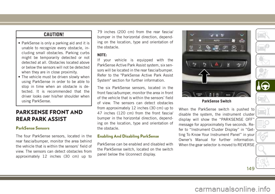
the ParkSense switch, located on the switch
panel below the Uconnect display.
When the ParkSense switch is pushed to
disable the system, the instrument cluster
display will show the “PARKSENSE OFF”
message for approximately five seconds. Re-
fer to “Instrument Cluster Display” in “Get-
ting To Know Your Instrument Panel” in your
Owner’s Manual for further information.
When the gear selector is moved to REVERSE
ParkSense Switch
149
Page 152 of 312
and the system is disabled, the instrument
cluster display will show the “PARKSENSE
OFF” message for as long as the vehicle is in
REVERSE.
The ParkSense switch LED will be on when
ParkSense is disabled or requires service.
The ParkSense switch LED will be off when
the system is enabled. If the ParkSense
switch is pushed, and requires service, the
ParkSense switch LED will blink momen-
tarily, and then the LED will be on.
Engagement/Disengagement
To disengage the system, push the ParkSense
switch, located on the switch panel below the
Uconnect display.
When the system passes from engaged to
disengaged and vice versa, it is always ac-
companied by a dedicated message in the
instrument cluster display.
System engaged:ParkSense switch LED off.
System disengaged: ParkSense switch LED on
constantly. The ParkSense switch LED lights up also in
the case of a ParkSense system failure. If the
button is pushed with a system failure, the
ParkSense switch LED flashes for about
5 seconds, then it stays on constantly.
After the ParkSense has been disengaged, it
will stay in this condition until the following
engagement, even if the ignition device
passes from ON/RUN to OFF and then again
to ON/RUN.
Operation With A Trailer
The operation of the sensors is automatically
deactivated when the trailer's electric plug is
inserted in the vehicle's tow hook socket. The
sensors are automatically reactivated when
the trailer's cable plug is removed.
General Warnings
If “PARKSENSE UNAVAILABLE WIPE REAR
SENSORS" or "PARKSENSE UNAVAILABLE
WIPE FRONT SENSORS” appears in the in-
strument cluster display, clean the
ParkSense sensors with water, car wash soap
and a soft cloth. Do not use rough or hard
cloths. Do not scratch or poke the sensors.
Otherwise, you could damage the sensors.
PARKSENSE ACTIVE PARK
ASSIST
Enabling And Disabling ParkSense Active
Park Assist
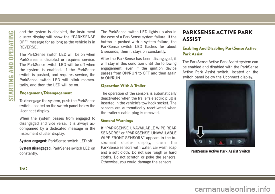
The ParkSense Active Park Assist system can
be enabled and disabled with the ParkSense
Active Park Assist switch, located on the
switch panel below the Uconnect display.
ParkSense Active Park Assist Switch
STARTING AND OPERATING
150
Page 153 of 312
The ParkSense Active Park Assist system is
intended to assist the driver during parallel
and perpendicular parking maneuvers by
identifying a proper parking space, providing
audible/visual instructions, and controlling
the steering wheel. The ParkSense Active
Park Assist system is defined as “semi-
automatic” since the driver maintains control
of the accelerator, gear selector and brakes.
Depending on the driver’s parking maneuver
selection, the ParkSense Active Park Assist
system is capable of maneuvering a vehicle
into a parallel or a perpendicular parking
space on either side (i.e., driver side or pas-
senger side).
NOTE:
The ParkSense Active Park Assist system
automatically defaults to looking for vehicles
on the right.To search for a parking spot on the
left, use the left turn signal.
Refer to your Owner's Manual for further
information.WARNING!
• Drivers must be careful when backing up even when using ParkSense. Always
check carefully behind your vehicle, look
behind you, and be sure to check for
pedestrians, animals, other vehicles, ob-
structions, and blind spots before back-
ing up. You are responsible for safety
and must continue to pay attention to
your surroundings. Failure to do so can
result in serious injury or death.
• Before using ParkSense, it is strongly
recommended that the ball mount and
hitch ball assembly is disconnected
from the vehicle when the vehicle is not
used for towing. Failure to do so can
result in injury or damage to vehicles or
obstacles because the hitch ball will be
much closer to the obstacle than the rear
fascia when the loudspeaker sounds the
continuous tone. Also, the sensors could
detect the ball mount and hitch ball
assembly, depending on its size and
shape, giving a false indication that an
obstacle is behind the vehicle.
CAUTION!
• ParkSense is only a parking aid and it isunable to recognize every obstacle, in-
cluding small obstacles. Parking curbs
might be temporarily detected or not
detected at all. Obstacles located above
or below the sensors will not be detected
when they are in close proximity.
• The vehicle must be driven slowly when
using ParkSense in order to be able to
stop in time when an obstacle is de-
tected. It is recommended that the
driver looks over his/her shoulder when
using ParkSense.
LANESENSE
LaneSense Operation
The LaneSense system is operational at
speeds above 37 mph (60 km/h) and below
112 mph (180 km/h). The LaneSense system
uses a forward looking camera to detect lane
markings and measure vehicle position
within the lane boundaries.
151
Page 154 of 312
When both lane markings are detected and
the driver unintentionally drifts out of the
lane (no turn signal applied), the LaneSense
system provides a haptic warning in the form
of torque applied to the steering wheel, as
well as a visual warning in the instrument
cluster display, to prompt the driver to remain
within the lane boundaries.
The driver may manually override the haptic
warning by applying torque into the steering
wheel at any time.
When only a single lane marking is detected
and the driver unintentionally drifts across the
lane marking (no turn signal applied), the
LaneSense system provides a visual warning
through the instrument cluster display to
prompt the driver to remain within the lane.
When only a single lane marking is detected, a
haptic (torque) warning will not be provided.
NOTE:
When operating conditions have been met,
the LaneSense system will monitor if thedriver’s hands are on the steering wheel and
provide an audible and visual warning to the
driver when the driver’s hands are not de-
tected on the steering wheel. The system will
cancel if the driver does not return their
hands to the wheel.
Turning LaneSense On Or Off
The default status of LaneSense is “off”.
The LaneSense button is located on the
switch panel below the Uconnect display.
To turn the LaneSense system on, push the
LaneSense button (LED turns off). A “Lane-
Sense On” message is shown in the instru-
ment cluster display.
To turn the LaneSense system off, push the
LaneSense button once (LED turns on).
NOTE:
The LaneSense system will retain the last
system state, on or off, from the last ignition
cycle when the ignition is changed to the
ON/RUN position.
LaneSense Warning Message
The LaneSense system will indicate the cur-
rent lane drift condition through the instru-
ment cluster display.
Base Instrument Cluster Display — If Equipped
When the LaneSense system is on; the lane
lines are gray when both of the lane bound-
aries have not been detected and the Lane-
Sense telltale is solid white.
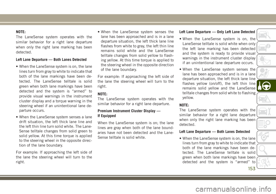
Left Lane Departure — Only Left Lane Detected
• When the LaneSense system is on, the
LaneSense telltale is solid white when only
the left lane marking has been detected
and the system is ready to provide visual
warnings in the instrument cluster display
if an unintentional lane departure occurs.
• When the LaneSense system senses the lane has been approached and is in a lane
departure situation, the left thick lane line
flashes from white to gray, the left thin line
remains solid white and the LaneSense
telltale changes from solid white to flashing
yellow.
STARTING AND OPERATING
152
Page 155 of 312
NOTE:
The LaneSense system operates with the
similar behavior for a right lane departure
when only the right lane marking has been
detected.
Left Lane Departure — Both Lanes Detected
• When the LaneSense system is on, the lanelines turn from gray to white to indicate that
both of the lane markings have been de-
tected. The LaneSense telltale is solid
green when both lane markings have been
detected and the system is “armed” to
provide visual warnings in the instrument
cluster display and a torque warning in the
steering wheel if an unintentional lane de-
parture occurs.
• When the LaneSense system senses a lane drift situation, the left thick lane line and
the left thin line turn solid white. The Lane-
Sense telltale changes from solid green to
solid yellow. At this time torque is applied
to the steering wheel in the opposite direc-
tion of the lane boundary.
For example: If approaching the left side of
the lane the steering wheel will turn to the
right. • When the LaneSense system senses the
lane has been approached and is in a lane
departure situation, the left thick lane line
flashes from white to gray, the left thin line
remains solid white and the LaneSense
telltale changes from solid yellow to flash-
ing yellow. At this time torque is applied to
the steering wheel in the opposite direction
of the lane boundary.
For example: If approaching the left side of
the lane the steering wheel will turn to the
right.
NOTE:
The LaneSense system operates with the
similar behavior for a right lane departure.
Premium Instrument Cluster Display —
If Equipped
When the LaneSense system is on; the lane
lines are gray when both of the lane bound-
aries have not been detected and the Lane-
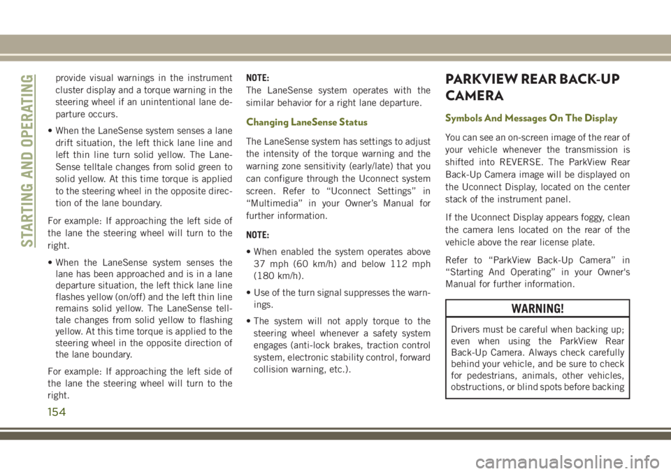
Sense telltale is solid white. Left Lane Departure — Only Left Lane Detected
• When the LaneSense system is on, the
LaneSense telltale is solid white when only
the left lane marking has been detected
and the system is ready to provide visual
warnings in the instrument cluster display
if an unintentional lane departure occurs.
• When the LaneSense system senses the lane has been approached and is in a lane
departure situation, the left thick lane line
flashes yellow (on/off), the left thin line
remains solid yellow and the LaneSense
telltale changes from solid white to flashing
yellow.
NOTE:
The LaneSense system operates with the
similar behavior for a right lane departure
when only the right lane marking has been
detected.
Left Lane Departure — Both Lanes Detected
• When the LaneSense system is on, the lane lines turn from gray to white to indicate that
both of the lane markings have been de-
tected. The LaneSense telltale is solid
green when both lane markings have been
detected and the system is “armed” to
153
Page 156 of 312
provide visual warnings in the instrument
cluster display and a torque warning in the
steering wheel if an unintentional lane de-
parture occurs.
• When the LaneSense system senses a lane drift situation, the left thick lane line and
left thin line turn solid yellow. The Lane-
Sense telltale changes from solid green to
solid yellow. At this time torque is applied
to the steering wheel in the opposite direc-
tion of the lane boundary.
For example: If approaching the left side of
the lane the steering wheel will turn to the
right.
• When the LaneSense system senses the lane has been approached and is in a lane
departure situation, the left thick lane line
flashes yellow (on/off) and the left thin line
remains solid yellow. The LaneSense tell-
tale changes from solid yellow to flashing
yellow. At this time torque is applied to the
steering wheel in the opposite direction of
the lane boundary.
For example: If approaching the left side of
the lane the steering wheel will turn to the
right. NOTE:
The LaneSense system operates with the
similar behavior for a right lane departure.
Changing LaneSense Status
The LaneSense system has settings to adjust
the intensity of the torque warning and the
warning zone sensitivity (early/late) that you
can configure through the Uconnect system
screen. Refer to “Uconnect Settings” in
“Multimedia” in your Owner’s Manual for
further information.
NOTE:
• When enabled the system operates above
37 mph (60 km/h) and below 112 mph
(180 km/h).
• Use of the turn signal suppresses the warn- ings.
• The system will not apply torque to the steering wheel whenever a safety system
engages (anti-lock brakes, traction control
system, electronic stability control, forward
collision warning, etc.).
PARKVIEW REAR BACK-UP
CAMERA
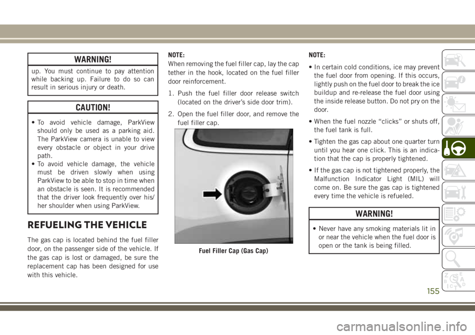
Symbols And Messages On The Display
You can see an on-screen image of the rear of
your vehicle whenever the transmission is
shifted into REVERSE. The ParkView Rear
Back-Up Camera image will be displayed on
the Uconnect Display, located on the center
stack of the instrument panel.
If the Uconnect Display appears foggy, clean
the camera lens located on the rear of the
vehicle above the rear license plate.
Refer to “ParkView Back-Up Camera” in
“Starting And Operating” in your Owner's
Manual for further information.
WARNING!
Drivers must be careful when backing up;
even when using the ParkView Rear
Back-Up Camera. Always check carefully
behind your vehicle, and be sure to check
for pedestrians, animals, other vehicles,
obstructions, or blind spots before backing
STARTING AND OPERATING
154
Page 157 of 312
WARNING!
up. You must continue to pay attention
while backing up. Failure to do so can
result in serious injury or death.
CAUTION!
• To avoid vehicle damage, ParkViewshould only be used as a parking aid.
The ParkView camera is unable to view
every obstacle or object in your drive
path.
• To avoid vehicle damage, the vehicle
must be driven slowly when using
ParkView to be able to stop in time when
an obstacle is seen. It is recommended
that the driver look frequently over his/
her shoulder when using ParkView.
REFUELING THE VEHICLE
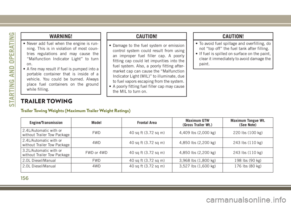
The gas cap is located behind the fuel filler
door, on the passenger side of the vehicle. If
the gas cap is lost or damaged, be sure the
replacement cap has been designed for use
with this vehicle. NOTE:
When removing the fuel filler cap, lay the cap
tether in the hook, located on the fuel filler
door reinforcement.
1. Push the fuel filler door release switch
(located on the driver’s side door trim).
2. Open the fuel filler door, and remove the fuel filler cap. NOTE:
• In certain cold conditions, ice may prevent
the fuel door from opening. If this occurs,
lightly push on the fuel door to break the ice
buildup and re-release the fuel door using
the inside release button. Do not pry on the
door.
• When the fuel nozzle “clicks” or shuts off, the fuel tank is full.
• Tighten the gas cap about one quarter turn until you hear one click. This is an indica-
tion that the cap is properly tightened.
• If the gas cap is not tightened properly, the Malfunction Indicator Light (MIL) will
come on. Be sure the gas cap is tightened
every time the vehicle is refueled.
WARNING!
• Never have any smoking materials lit in or near the vehicle when the fuel door is
open or the tank is being filled.
Fuel Filler Cap (Gas Cap)
155
Page 158 of 312
WARNING!
• Never add fuel when the engine is run-ning. This is in violation of most coun-
tries regulations and may cause the
“Malfunction Indicator Light” to turn
on.
• A fire may result if fuel is pumped into a
portable container that is inside of a
vehicle. You could be burned. Always
place fuel containers on the ground
while filling.
CAUTION!
• Damage to the fuel system or emissioncontrol system could result from using
an improper fuel filler cap. A poorly
fitting cap could let impurities into the
fuel system. Also, a poorly fitting after-
market cap can cause the “Malfunction
Indicator Light (MIL)” to illuminate, due
to fuel vapors escaping from the system.
• A poorly fitting fuel filler cap may cause
the MIL to turn on.
CAUTION!
• To avoid fuel spillage and overfilling, donot “top off” the fuel tank after filling.
• If fuel is spilled on surface on the paint,
clear it immediately to avoid damage the
paint.
TRAILER TOWING
Trailer Towing Weights (Maximum Trailer Weight Ratings)
Engine/Transmission ModelFrontal Area Maximum GTW
(Gross Trailer Wt.) Maximum Tongue Wt.
(See Note)
2.4L/Automatic with or
without Trailer Tow Package FWD
40 sq ft (3.72 sq m) 4,409 lbs (2,000 kg) 220 lbs (100 kg)
2.4L/Automatic with or
without Trailer Tow Package 4WD
40 sq ft (3.72 sq m) 4,850 lbs (2,200 kg) 243 lbs (110 kg)
3.2L/Automatic with or
without Trailer Tow Package FWD or 4WD
40 sq ft (3.72 sq m) 4,850 lbs (2,200 kg) 243 lbs (110 kg)
2.0L Diesel/Manual FWD40 sq ft (3.72 sq m) 3,968 lbs (1,800 kg) 198 lbs (90 kg)
2.0L Diesel/Manual 4WD40 sq ft (3.72 sq m) 3,527 lbs (1,600 kg) 176 lbs (80 kg)
STARTING AND OPERATING
156
Page 159 of 312
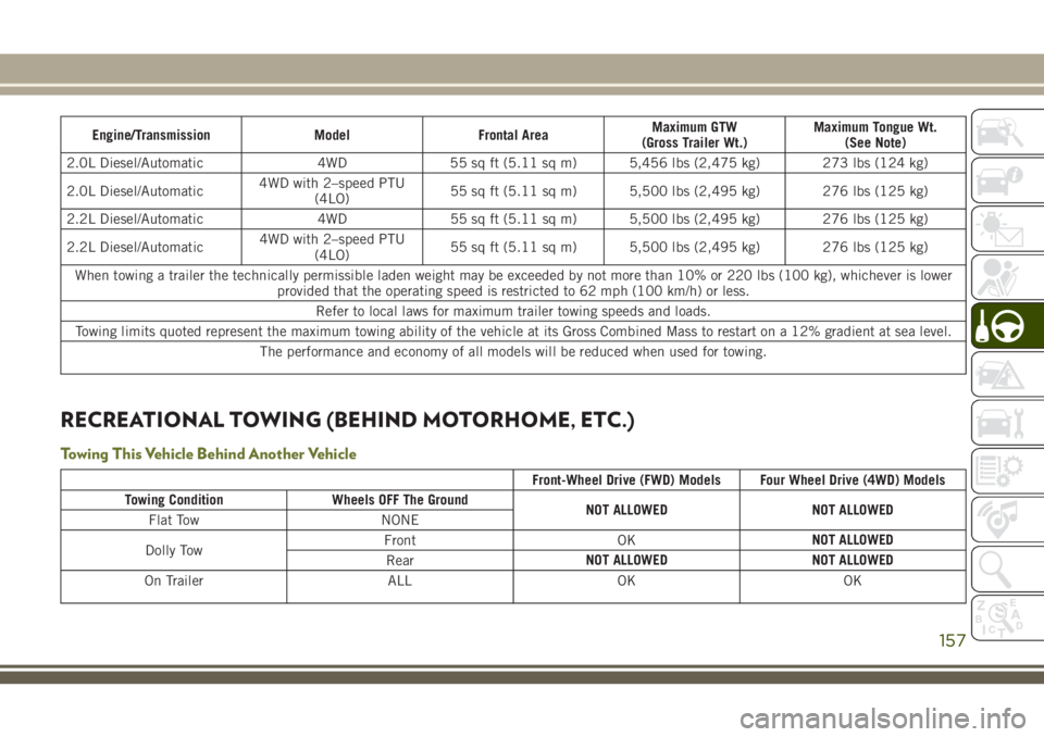
Engine/TransmissionModelFrontal Area Maximum GTW
(Gross Trailer Wt.) Maximum Tongue Wt.
(See Note)
2.0L Diesel/Automatic 4WD55 sq ft (5.11 sq m) 5,456 lbs (2,475 kg) 273 lbs (124 kg)
2.0L Diesel/Automatic 4WD with 2–speed PTU
(4LO) 55 sq ft (5.11 sq m) 5,500 lbs (2,495 kg) 276 lbs (125 kg)
2.2L Diesel/Automatic 4WD55 sq ft (5.11 sq m) 5,500 lbs (2,495 kg) 276 lbs (125 kg)
2.2L Diesel/Automatic 4WD with 2–speed PTU
(4LO) 55 sq ft (5.11 sq m) 5,500 lbs (2,495 kg) 276 lbs (125 kg)
When towing a trailer the technically permissible laden weight may be exceeded by not more than 10% or 220 lbs (100 kg), whichever is lower provided that the operating speed is restricted to 62 mph (100 km/h) or less.
Refer to local laws for maximum trailer towing speeds and loads.
Towing limits quoted represent the maximum towing ability of the vehicle at its Gross Combined Mass to restart on a 12% gradient at sea level.
The performance and economy of all models will be reduced when used for towing.
RECREATIONAL TOWING (BEHIND MOTORHOME, ETC.)
Towing This Vehicle Behind Another Vehicle
Front-Wheel Drive (FWD) Models Four Wheel Drive (4WD) Models
Towing Condition Wheels OFF The Ground
NOT ALLOWEDNOT ALLOWED
Flat Tow NONE
Dolly Tow Front
OKNOT ALLOWED
Rear NOT ALLOWED
NOT ALLOWED
On Trailer ALLOKOK
157
Page 160 of 312
NOTE:
• You must ensure that the Auto Park Brakefeature is disabled before towing this ve-
hicle, to avoid inadvertent Electric Park
Brake engagement. The Auto Park Brake
feature is enabled or disabled via the cus-
tomer programmable features in the
Uconnect Settings.
• When towing your vehicle, always follow applicable state and provincial laws. Con-
tact state and provincial Highway Safety
offices for additional details.
Recreational Towing — Front-Wheel Drive
(FWD) Models
DO NOT flat tow this vehicle.
Recreational towing (for front-wheel drive
models) is allowed ONLY if the front wheels
are OFF the ground. This may be accom-
plished using a tow dolly or vehicle trailer. If
using a tow dolly, follow this procedure:
1. Properly secure the dolly to the tow ve- hicle, following the dolly manufacturer's
instructions. 2. Drive the front wheels onto the tow dolly.
3. Apply the parking brake. Place automatic
transmission in PARK, or manual trans-
mission in gear. Turn the engine OFF.
4. Properly secure the front wheels to the dolly, following the dolly manufacturer's
instructions.
5. Turn the ignition to the ON/RUN mode, but do not start the engine.
6. Press and hold the brake pedal.
7. Release the parking brake.
8. Turn the ignition OFF, remove the key fob, and release the brake pedal.
CAUTION!
• Towing with the front wheels on theground will cause severe transmission
damage. Damage from improper towing
is not covered under the New Vehicle
Limited Warranty.
CAUTION!
• Ensure that the Electric Park Brake isreleased, and remains released, while
being towed.
Recreational Towing — 4x4 Models
Recreational towing is not allowed.
NOTE:
This vehicle may be towed on a flatbed or
vehicle trailer provided all four wheels are
OFF the ground.
CAUTION!
Towing this vehicle with ANYof its wheels
on the ground can cause severe transmis-
sion and/or power transfer unit damage.
Damage from improper towing is not cov-
ered under the New Vehicle Limited War-
ranty.
STARTING AND OPERATING
158