Instrument panel JEEP CHEROKEE 2018 Owner handbook (in English)
[x] Cancel search | Manufacturer: JEEP, Model Year: 2018, Model line: CHEROKEE, Model: JEEP CHEROKEE 2018Pages: 312, PDF Size: 4.91 MB
Page 7 of 312
GRAPHICAL TABLE OF CONTENTS
GETTING TO KNOW YOUR VEHICLE
GETTING TO KNOW YOUR INSTRUMENT PANEL SAFETY
STARTING AND OPERATING IN CASE OF EMERGENCY
SERVICING AND MAINTENANCE TECHNICAL SPECIFICATIONS MULTIMEDIA
CUSTOMER ASSISTANCE INDEX
Page 9 of 312
GRAPHICAL TABLE OF CONTENTS
INSTRUMENT PANEL...........8
INTERIOR ...................9
GRAPHICAL TABLE OF CONTENTS
7
Page 10 of 312
INSTRUMENT PANEL
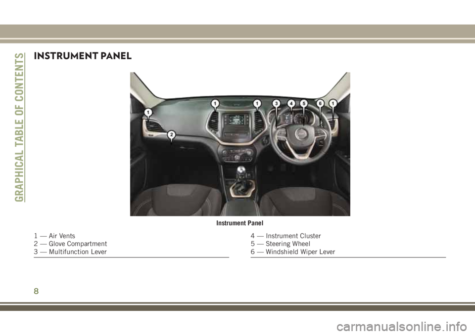
Instrument Panel
1 — Air Vents
2 — Glove Compartment
3 — Multifunction Lever4 — Instrument Cluster
5 — Steering Wheel
6 — Windshield Wiper Lever
GRAPHICAL TABLE OF CONTENTS
8
Page 15 of 312
KEYS
Key Fob
The key fob operates the ignition switch.
Insert the square end of the key fob into the
ignition switch located on the instrument
panel and rotate to the desired position. The
key fob also contains an emergency key,
which is stored in the rear of the key fob.Your vehicle may be equipped with a keyless
ignition system. The ignition system consists
of a key fob with Remote Keyless Entry (RKE)
and a START/STOP push button ignition sys-
tem. The Remote Keyless Entry system con-
sists of a key fob and Keyless Enter-N-Go
feature if equipped.
NOTE:
The key fob may not be found if it is located
next to a mobile phone, laptop or other elec-
tronic device; these devices may block the
key fob’s wireless signal.
The key fob allows you to lock or unlock the
doors and liftgate from distances up to ap-
proximately 66 ft (20 m) using a handheld
key fob. The key fob does not need to be
pointed at the vehicle to activate the system.
• This feature allows the driver to operate the
ignition switch with the push of a button as
long as the key fob is in the passenger
compartment.
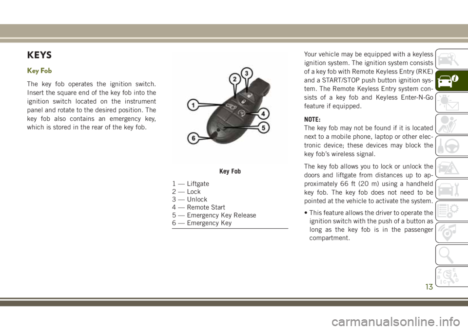
Key Fob
1 — Liftgate
2 — Lock
3 — Unlock
4 — Remote Start
5 — Emergency Key Release
6 — Emergency Key
13
Page 32 of 312
EXTERIOR LIGHTS
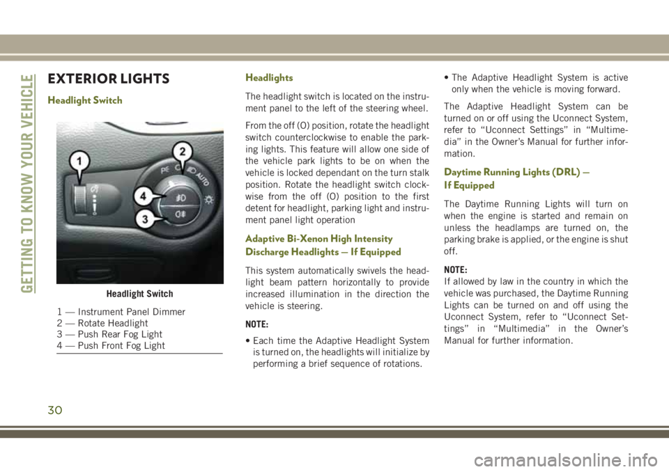
Headlight SwitchHeadlightsThe headlight switch is located on the instru-
ment panel to the left of the steering wheel.
From the off (O) position, rotate the headlight
switch counterclockwise to enable the park-
ing lights. This feature will allow one side of
the vehicle park lights to be on when the
vehicle is locked dependant on the turn stalk
position. Rotate the headlight switch clock-
wise from the off (O) position to the first
detent for headlight, parking light and instru-
ment panel light operation
Adaptive Bi-Xenon High Intensity
Discharge Headlights — If Equipped
This system automatically swivels the head-
light beam pattern horizontally to provide
increased illumination in the direction the
vehicle is steering.
NOTE:
• Each time the Adaptive Headlight System
is turned on, the headlights will initialize by
performing a brief sequence of rotations. • The Adaptive Headlight System is active
only when the vehicle is moving forward.
The Adaptive Headlight System can be
turned on or off using the Uconnect System,
refer to “Uconnect Settings” in “Multime-
dia” in the Owner’s Manual for further infor-
mation.
Daytime Running Lights (DRL) —
If Equipped
The Daytime Running Lights will turn on
when the engine is started and remain on
unless the headlamps are turned on, the
parking brake is applied, or the engine is shut
off.
NOTE:
If allowed by law in the country in which the
vehicle was purchased, the Daytime Running
Lights can be turned on and off using the
Uconnect System, refer to “Uconnect Set-
tings” in “Multimedia” in the Owner’s
Manual for further information.
Headlight Switch
1 — Instrument Panel Dimmer
2 — Rotate Headlight
3 — Push Rear Fog Light
4 — Push Front Fog Light
GETTING TO KNOW YOUR VEHICLE
30
Page 42 of 312
IconDescription
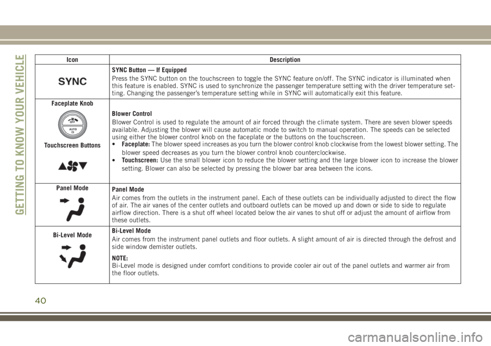
SYNC Button — If Equipped
Press the SYNC button on the touchscreen to toggle the SYNC feature on/off. The SYNC indicator is illuminated when
this feature is enabled. SYNC is used to synchronize the passenger temperature setting with the driver temperature set-
ting. Changing the passenger’s temperature setting while in SYNC will automatically exit this feature.
Faceplate Knob
Touchscreen Buttons
Blower Control
Blower Control is used to regulate the amount of air forced through the climate system. There are seven blower speeds
available. Adjusting the blower will cause automatic mode to switch to manual operation. The speeds can be selected
using either the blower control knob on the faceplate or the buttons on the touchscreen.
• Faceplate: The blower speed increases as you turn the blower control knob clockwise from the lowest blower setting. The
blower speed decreases as you turn the blower control knob counterclockwise.
• Touchscreen:
Use the small blower icon to reduce the blower setting and the large blower icon to increase the blower
setting. Blower can also be selected by pressing the blower bar area between the icons.
Panel Mode
Panel Mode
Air comes from the outlets in the instrument panel. Each of these outlets can be individually adjusted to direct the flow
of air. The air vanes of the center outlets and outboard outlets can be moved up and down or side to side to regulate
airflow direction. There is a shut off wheel located below the air vanes to shut off or adjust the amount of airflow from
these outlets.
Bi-Level Mode
Bi-Level Mode
Air comes from the instrument panel outlets and floor outlets. A slight amount of air is directed through the defrost and
side window demister outlets.
NOTE:
Bi-Level mode is designed under comfort conditions to provide cooler air out of the panel outlets and warmer air from
the floor outlets.
GETTING TO KNOW YOUR VEHICLE
40
Page 49 of 312
Manual Open
To open the shade, push and hold the switch
rearward. The shade will open and stop auto-
matically at the half-open position.
Push and hold the shade switch rearward
again and the shade will open automatically
to the full-open position.
Express Close
Push the switch forward and release it within
one-half second and the shade will close
automatically from any position.
Manual Close
To close the shade, push and hold the switch
in the forward position.
Pinch Protection Feature
This feature will detect an obstruction in the
opening of the sunroof during Express Close
operation. If an obstruction in the path of the
sunroof is detected, the sunroof will auto-
matically retract. Remove the obstruction if
this occurs. Next, push the switch forward
and release to Express Close.NOTE:
If three consecutive sunroof close attempts
result in Pinch Protect reversals, the fourth
close attempt will be a Manual Close move-
ment with Pinch Protect disabled.
WARNING!
• Do not let children play with the sunroof.
Never leave children unattended in a
vehicle, or with access to an unlocked
vehicle. Do not leave the key fob in or
near the vehicle, and do not leave the
ignition of a vehicle equipped with Key-
less Enter-N-Go in the ACC or ON/RUN
mode. Occupants, particularly unat-
tended children, can become entrapped
by the power sunroof while operating the
power sunroof switch. Such entrapment
may result in serious injury or death.
• In a collision, there is a greater risk of
being thrown from a vehicle with an
open sunroof. You could also be severely
injured or killed. Always fasten your seat
belt properly and make sure all passen-
gers are properly secured.
WARNING!
• Do not allow small children to operatethe sunroof. Never allow your fingers,
other body parts, or any object to project
through the sunroof opening. Injury may
result.
Sunroof Maintenance
Use only a non-abrasive cleaner and a soft
cloth to clean the glass panel.
HOOD
Opening The Hood
Two latches must be released to open the
hood.
1. Pull the hood release lever located under the driver’s side of the instrument panel.
47
Page 55 of 312
GETTING TO KNOW YOUR INSTRUMENT PANEL
INSTRUMENT CLUSTER
DISPLAY...................54
Instrument Cluster Display Controls ....54
Oil Change Reset — If Equipped ......55
Instrument Cluster Display Selectable
Items ......................55
WARNING LIGHTS AND
MESSAGES.................56
Red Warning Lights ..............56
Yellow Warning Lights ............59
Yellow Indicator Lights ............63
Green Indicator Lights ............63 White Indicator Lights
............64
Blue Indicator Lights .............65ONBOARD DIAGNOSTIC
SYSTEM—OBDII ............66
Onboard Diagnostic System (OBD II)
Cybersecurity.................66
GETTING TO KNOW YOUR INSTRUMENT PANEL
53
Page 56 of 312
INSTRUMENT CLUSTER
DISPLAY
Your vehicle may be equipped with an instru-
ment cluster display, which offers useful in-
formation to the driver. With the ignition in
the STOP/OFF mode, opening/closing of a
door will activate the display for viewing, and
display the total miles, or kilometers, in the
odometer. Your instrument cluster display is
designed to display important information
about your vehicle’s systems and features.
Using a driver interactive display located on
the instrument panel, your instrument clus-
ter display can show you how systems are
working and give you warnings when they
aren’t. The steering wheel mounted controls
allow you to scroll through and enter the main
menus and submenus. You can access the
specific information you want and make se-
lections and adjustments.
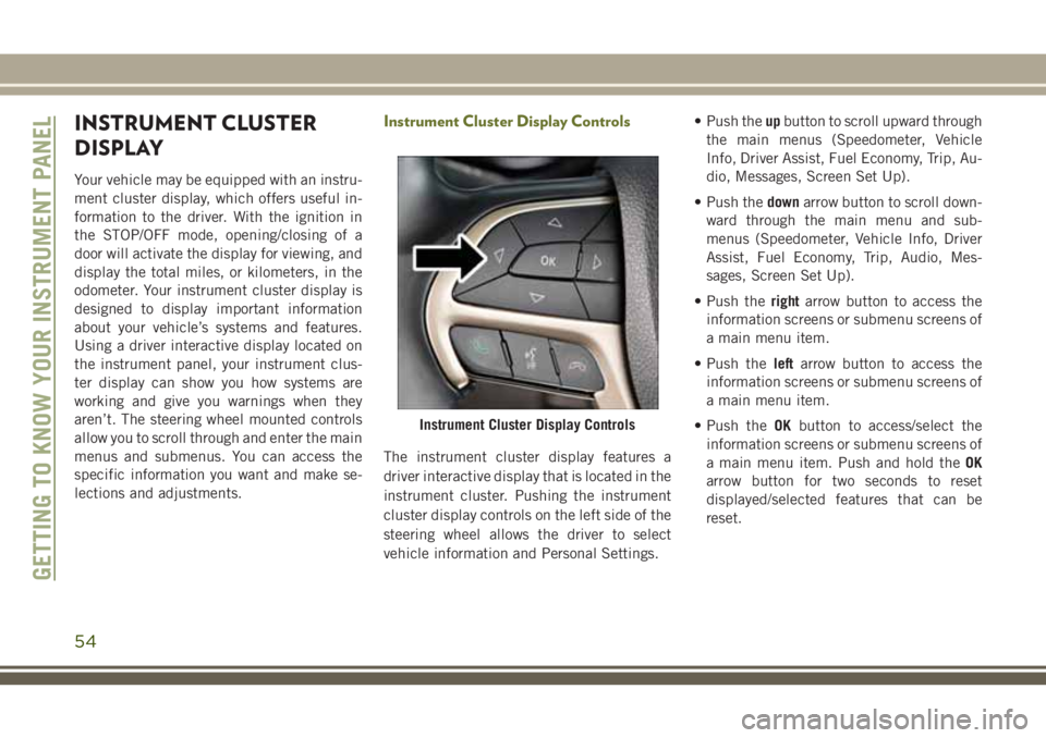
Instrument Cluster Display Controls
The instrument cluster display features a
driver interactive display that is located in the
instrument cluster. Pushing the instrument
cluster display controls on the left side of the
steering wheel allows the driver to select
vehicle information and Personal Settings.• Push the
upbutton to scroll upward through
the main menus (Speedometer, Vehicle
Info, Driver Assist, Fuel Economy, Trip, Au-
dio, Messages, Screen Set Up).
• Push the downarrow button to scroll down-
ward through the main menu and sub-
menus (Speedometer, Vehicle Info, Driver
Assist, Fuel Economy, Trip, Audio, Mes-
sages, Screen Set Up).
• Push the rightarrow button to access the
information screens or submenu screens of
a main menu item.
• Push the leftarrow button to access the
information screens or submenu screens of
a main menu item.
• Push the OKbutton to access/select the
information screens or submenu screens of
a main menu item. Push and hold the OK
arrow button for two seconds to reset
displayed/selected features that can be
reset.
Instrument Cluster Display Controls
GETTING TO KNOW YOUR INSTRUMENT PANEL
54
Page 57 of 312
Oil Change Reset — If Equipped
Your vehicle is equipped with an engine oil
change indicator system. The “Oil Change
Required” message will display in the instru-
ment cluster display for five seconds after a
single chime has sounded to indicate the
next scheduled oil change interval. The en-
gine oil change indicator system is duty cycle
based, which means the engine oil change
interval may fluctuate, dependent upon your
personal driving style.
Unless reset, this message will continue to
display each time you cycle the ignition to the
ON/RUN position. To turn off the message
temporarily, push and release theOKbutton.
To reset the oil change indicator system (after
performing the scheduled maintenance), re-
fer to the following procedure.
Oil Life Reset
1. Without pushing the brake pedal, push and release the ENGINE START/STOP
button and place the ignition to the ON/
RUN position (do not start the engine). 2. Navigate to "Oil Life" submenu in "Vehicle
Info" in the instrument cluster display.
3. Push and hold the OKbutton until the
gauge resets to 100%.
Secondary Method For Oil Change Reset Proce-
dure
1. Without pushing the brake pedal, push and release the ENGINE START/STOP
button and place the ignition to the ON/
RUN position (do not start the engine).
2. Fully press the accelerator pedal, slowly, three times within ten seconds.
3. Without pushing the brake pedal, push and release the ENGINE START/STOP
button once to return the ignition to the
OFF/LOCK position.
NOTE:
If the indicator message illuminates when
you start the vehicle, the oil change indicator
system did not reset. If necessary, repeat this
procedure.
Instrument Cluster Display Selectable
Items
The instrument cluster display can be used to
view the following main menu items:
Speedometer Stop/Start
Vehicle Info Audio
Driver Assist Messages
Fuel Economy Screen Setup
Trip Gear Shift Indicator (GSI)
NOTE:
Depending on the vehicles options, feature
settings may vary. Refer to the “Instrument
Cluster Display” in “Getting To know Your
Instrument Panel” in the Owner’s Manual for
further information.
55