tow JEEP CHEROKEE 2019 Owner handbook (in English)
[x] Cancel search | Manufacturer: JEEP, Model Year: 2019, Model line: CHEROKEE, Model: JEEP CHEROKEE 2019Pages: 344, PDF Size: 6.35 MB
Page 206 of 344
TIRE SERVICE KIT — IF
EQUIPPED
Small punctures up to 1/4 inch (6 mm) in the
tire tread can be sealed with Tire Service Kit.
Foreign objects (e.g., screws or nails) should
not be removed from the tire. Tire Service Kit
can be used in outside temperatures down to
approximately -4°F (-20°C).
This kit will provide a temporary tire seal,
allowing you to drive your vehicle up to 100
miles (160 km) with a maximum speed of
50 mph (80 km/h).
Tire Service Kit Storage
The Tire Service Kit is stowed under the load
floor behind the rear seat.
1. Open the liftgate.
2. Lift the access cover using the load floor
handle.
Tire Service Kit Components And
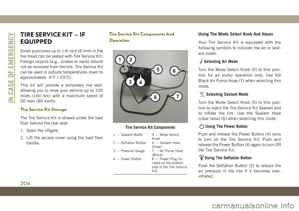
OperationUsing The Mode Select Knob And Hoses
Your Tire Service Kit is equipped with the
following symbols to indicate the air or seal-
ant mode.
Selecting Air Mode
Turn the Mode Select Knob (5) to this posi-
tion for air pump operation only. Use the
Black Air Pump Hose (7) when selecting this
mode.
Selecting Sealant Mode
Turn the Mode Select Knob (5) to this posi-
tion to inject the Tire Service Kit Sealant and
to inflate the tire. Use the Sealant Hose
(clear hose) (6) when selecting this mode.
Using The Power Button
Push and release the Power Button (4) once
to turn on the Tire Service Kit. Push and
release the Power Button (4) again to turn Off
the Tire Service Kit.
Using The Deflation Button
Push the Deflation Button (2) to reduce the
air pressure in the tire if it becomes over-
inflated.
Tire Service Kit Components
1 — Sealant Bottle 5 — Mode Select
Knob
2 — Deflation Button 6 — Sealant Hose
(Clear)
3 — Pressure Gauge 7 — Air Pump Hose
(Black)
4 — Power Button 8 — Power Plug (lo-
cated on the bottom
side of the Tire Service
Kit)
IN CASE OF EMERGENCY
204
Page 207 of 344
Tire Service Kit Usage Precautions
• Replace the Tire Service Kit Sealant Bottle
(1) and Sealant Hose (6) prior to the expi-
ration date (printed at the lower right hand
corner on the bottle label) to assure opti-
mum operation of the system.
NOTE:
Refer to section “(F) Sealant Bottle And Hose
Replacement” in “Sealing A Tire With Tire
Service Kit” in this section.
• The Sealant Bottle (1) and Sealant Hose (6)
are a one tire application use and need to
be replaced after each use. Always replace
these components immediately at your
original equipment vehicle dealer.
• When the Tire Service Kit sealant is in a
liquid form, clean water and a damp cloth
will remove the material from the vehicle or
tire and wheel components. Once the seal-
ant dries, it can easily be peeled off and
properly discarded.• For optimum performance, make sure the
valve stem on the wheel is free of debris
before connecting the Tire Service Kit.
• You can use the Tire Service Kit air pump to
inflate bicycle tires. The kit also comes with
two needles, located in the Accessory Stor-
age Compartment (on the bottom of the air
pump) for inflating sport balls, rafts, or
similar inflatable items. However, use only
the Air Pump Hose (7) and make sure the
Mode Select Knob (5) is in the Air Mode
when inflating such items to avoid injecting
sealant into them. The Tire Service Kit
Sealant is only intended to seal punctures
less than 1/4 inch (6 mm) diameter in the
tread of your vehicle.
• Do not lift or carry the Tire Service Kit by the
hoses.
WARNING!
• Do not attempt to seal a tire on the side
of the vehicle closest to traffic. Pull far
enough off the road to avoid the danger
of being hit when using the Tire Service
Kit.
WARNING!
• Do not use Tire Service Kit or drive the
vehicle under the following circum-
stances:
– If the puncture in the tire tread is
approximately 1/4 inch (6 mm) or
larger.
– If the tire has any sidewall damage.
– If the tire has any damage from
driving with extremely low tire pres-
sure.
– If the tire has any damage from
driving on a flat tire.
– If the wheel has any damage.
– If you are unsure of the condition of
the tire or the wheel.
• Keep Tire Service Kit away from open
flames or heat source.
• A loose Tire Service Kit thrown forward in
a collision or hard stop could endanger
the occupants of the vehicle. Always
stow the Tire Service Kit in the place
provided. Failure to follow these warn-
ings can result in injuries that are seri-
ous or fatal to you, your passengers, and
others around you.
205
Page 216 of 344
NOTE:
Push the “ESC Off” switch (if necessary), to
place the Electronic Stability Control (ESC)
system in “Partial Off” mode, before rocking
the vehicle. Refer to “Electronic Brake Con-
trol System” in “Safety” for further informa-
tion. Once the vehicle has been freed, push
the "ESC Off" switch again to restore “ESC
On” mode.WARNING!
Fast spinning tires can be dangerous.
Forces generated by excessive wheel
speeds may cause damage, or even failure,
of the axle and tires. A tire could explode
and injure someone. Do not spin your
vehicle's wheels faster than 30 mph
(48 km/h) or for longer than 30 seconds
continuously without stopping when you
are stuck and do not let anyone near a
spinning wheel, no matter what the speed.
TOWING A DISABLED
VEHICLE
This section describes procedures for towing
a disabled vehicle using a commercial towing
service.
Towing Condition Wheels OFF The
GroundFWD MODELS 4X4 MODELS
Flat Tow NONENOT ALLOWED NOT ALLOWED
Wheel Lift Or Dolly TowRearNOT ALLOWED NOT ALLOWED
Front OKNOT ALLOWED
FlatbedALL BEST METHOD ONLY METHOD
Proper towing or lifting equipment is required
to prevent damage to your vehicle. Use only
tow bars and other equipment designed for
this purpose, following equipment manufac-
turer’s instructions. Use of safety chains is
mandatory. Attach a tow bar or other towingdevices to main structural members of the
vehicle, not to bumpers or associated brack-
ets. State and local laws regarding vehicles
under tow must be observed.
IN CASE OF EMERGENCY
214
Page 217 of 344
NOTE:
• You must ensure that the Auto Park Brake
feature is disabled before towing this ve-
hicle, to avoid inadvertent Electric Park
Brake engagement. The Auto Park Brake
feature is enabled or disabled via the cus-
tomer programmable features in the
Uconnect Settings.
• Vehicles with a discharged battery or total
electrical failure when the electric park
brake (EPB) is engaged, will need a wheel
dolly or jack to raise the rear wheels off the
ground when moving the vehicle onto a
flatbed.
If you must use the accessories (wipers, de-
frosters, etc.) while being towed, the ignition
must be in the ON/RUN mode, not the ACC
mode.
Note that the Safehold feature will engage
the Electric Park Brake whenever the driver's
door is opened (if the battery is connected,
ignition is ON, transmission is not in PARK,
and brake pedal is released). If you are towing
this vehicle with the ignition in the ON/RUNmode, you must manually disable the Elec-
tric Park Brake each time the driver's door is
opened, by pressing the brake pedal and then
releasing the EPB.
If the vehicle’s battery is discharged, refer to
“Gear Selector Override” in this section for
instructions on shifting the automatic trans-
mission out of PARK so that the vehicle can
be moved.
CAUTION!
• Do not use sling-type equipment when
towing. Vehicle damage may occur.
• When securing the vehicle to a flatbed
truck, do not attach to front or rear
suspension components. Damage to
your vehicle may result from improper
towing.
• Ensure that the Electric Park Brake is
released, and remains released, while
being towed.
Without The Key Fob
Special care must be taken when the vehicle
is towed with the ignition in the LOCK/OFF
mode. The only approved method of towing
without the key fob is with a flatbed truck.
Proper towing equipment is necessary to pre-
vent damage to the vehicle.
Front-Wheel Drive (FWD) Models
The manufacturer recommends towing your
vehicle with all four wheelsOFFthe ground
using a flatbed.
If flatbed equipment is not available, this
vehicle must be towed with the front wheels
OFF the ground (using a towing dolly, or
wheel lift equipment with the front wheels
raised).
Ensure that the Electric Park Brake is re-
leased, and remains released, while being
towed. The Electric Park Brake does not need
to be released, if all four wheels are off the
ground.
215
Page 218 of 344
CAUTION!
Towing this vehicle in violation of the
above requirements can cause severe en-
gine and/or transmission damage. Damage
from improper towing is not covered under
the New Vehicle Limited Warranty.
4x4 Models
The manufacturer requires towing with all
four wheelsOFFthe ground.
Acceptable methods are to tow the vehicle on
a flatbed, or with one end of vehicle raised
and the opposite end on a towing dolly.
CAUTION!
• Front or rear wheel lifts must not be used
(if the remaining wheels are on the
ground). Internal damage to the trans-
mission or power transfer unit will occur
if a front or rear wheel lift is used when
towing.
• Towing this vehicle in violation of the
above requirements can cause severe
transmission and/or power transfer unit
CAUTION!
damage. Damage from improper towing
is not covered under the New Vehicle
Limited Warranty.
Recovery Strap — If Equipped
Your vehicle may be included with a recovery
strap. Recovery straps do not act like tradi-
tional tow straps, chains, or winch cables.
WARNING!
Recovery straps should only be used in
emergencies to rescue stranded vehicles.
Only use Recovery straps on vehicles that
fit within the recommended GVW of your
recovery strap. Only attach recovery straps
to OE recommended anchor points or
emergency towing anchor points. Never
attach to tow ball or vehicle tie down point,
these are not designed for this purpose.
Never attach to vehicle steering, drive
train, or any other suspension compo-
nents. NEVER pull a strap over sharp
edges or abrasive surfaces that can dam-
age the recovery strap. NEVER use a dam-
WARNING!
aged strap, it has reduced strength. DO
NOT attempt to repair straps. ONLY per-
sons involved in the recovery should be in
either vehicle. No passengers. Anyone in-
side the vehicles can be struck by strap
recoil, causing serious injury. MOVE by-
standers at least 40 ft (12.2 m) from the
recovery area when using the recovery
strap.
Using Recovery Strap
1. Review all warnings and instructions first.
2. Position the recovery vehicle.
3. Connect the recovery strap.
4. Add a recovery damper or blanket.
5. Clear the danger zone.
6. Safely and slowly start pulling.
7. Disconnect the recovery strap after both
vehicles are secure and parked.
IN CASE OF EMERGENCY
216
Page 220 of 344
SCHEDULED SERVICING
Correct servicing is crucial for guaranteeing a
long life for the car under the best conditions.
For this reason, Jeep has planned a series of
checks and services at fixed distance inter-
vals and, where provided, at fixed time inter-
vals, as described in the Scheduled Servicing
plan. To keep the car’s efficiency in tip-top
condition, in the following Scheduled Service
plan pages a few additional checks are listed
that should be carried out more frequently
with respect to the normal coupon redemp-
tion schedule. Scheduled Servicing is offered
by all authorized dealerships according to
fixed time or mileage intervals. If, during
each operation, in addition to the ones
scheduled, the need arises for further re-
placements or repairs, these may be carried
out with the owner's explicit agreement only.
The technicians at your dealership know your
vehicle best, and have access to factory
trained information, genuine Mopar parts,
and specially designed electronic and me-
chanical tools that can help prevent future
costly repairs. If your car is used frequently
for towing, the interval between one sched-uled servicing operation and the next should
be reduced. More frequent maintenance may
be needed for vehicles in severe operating
conditions, such as dusty areas and very
short trip driving.
NOTE:
Scheduled Servicing interventions are set out
by the Manufacturer. Failure to have them
carried out may invalidate the warranty. It is
advised to inform an authorized dealership of
any small operating irregularities without
waiting for the next service.
Scheduled Servicing — Gasoline Engine
The oil change indicator system will remind
you that it is time to take your vehicle in for
engine oil replacement.
An “Oil Change Required” will be displayed
in the instrument cluster and a single chime
will sound, indicating that an oil change is
necessary.
The oil change indicator message will illumi-
nate approximately 7,000 miles
(11,200 km) after the most recent oil change
was performed. Have your vehicle serviced assoon as possible, within 500 miles (800 km)
(except for 2.0L gasoline engine with GPF –
Gasoline Particulate Filter).
NOTE:
• The oil change indicator message will not
monitor the time since the last oil change.
Change your vehicle’s oil if it has been
12 months since your last oil change even
if the oil change indicator message is NOT
illuminated.
• Change your engine oil more often if you
drive your vehicle off-road for an extended
period of time (refer to the “Heavy Duty
Use” section).
• Under no circumstances should oil change
intervals exceed 7,500 miles (12,000 km)
or 12 months, whichever comes first (ex-
cept for 2.0L gasoline engine with GPF –
Gasoline Particulate Filter).
Your authorized dealer will reset the oil
change indicator message after completing
the scheduled oil change.
SERVICING AND MAINTENANCE
218
Page 224 of 344
* The actual interval for changing the oil and
replacing engine oil filter depends on vehicle
usage conditions, it is signaled by the warn-
ing light or message (if equipped) in the
instrument cluster. It should not exceed
10,000 miles (16,000 km) or 12 months.
** See “Heavy Duty Use Of The Vehicle” in
this section.
*** DOT 4 brake fluid interval is time based
only, mileage intervals do not apply.
**** The spark plug change interval is mile-
age based only, yearly intervals do not apply.
***** This maintenance is recommended by
the manufacturer to the owner, but is not
required to maintain emissions warranty.
WARNING!
• You can be badly injured working on or
around a motor vehicle. Do only service
work for which you have the knowledge
and the right equipment. If you have any
doubt about your ability to perform a
service job, take your vehicle to a com-
petent mechanic.
WARNING!
• Failure to properly inspect and maintain
your vehicle could result in a component
malfunction and effect vehicle handling
and performance. This could cause an
accident.
Heavy Duty Use Of Vehicle
Change the engine oil and engine oil filter at
every 4500 miles (7,500 km) or 12 months if
using your vehicle under any of the following
severe duty conditions:
• Stop and go driving.
• Driving in dusty conditions.
• Short trips of less than 10 miles (16 km).
• Trailer towing.
• Taxi, police, or delivery service (commercial
service).
• Off-road or desert operation.
Scheduled Servicing — Diesel Engine
Your vehicle is equipped with an automatic
oil change indicator system. The oil change
indicator system will remind you that it is
time to take your vehicle in for engine oil
replacement.
Based on engine operation conditions, the oil
change indicator message will illuminate.
This means that service is required for your
vehicle. Operating conditions such as fre-
quent short-trips, trailer tow, extremely hot or
cold ambient temperatures will influence
when the “Oil Change Required” message is
displayed. Severe Operating Conditions can
cause the change oil message to illuminate
as earlier than specified. Have your vehicle
serviced as soon as possible, within the next
500 miles (805 km).
To help you have the best driving experience
possible, the manufacturer has identified the
specific vehicle maintenance service inter-
vals that are required to keep your vehicle
operating properly and safely.
SERVICING AND MAINTENANCE
222
Page 227 of 344
Mileage or time passed (whichever comes first)12,500
25,000
37,500
50,000
62,500
75,000
87,500
100,000
112,500
125,000
137,500
150,000
162,500
175,000
187,500
Or Years: 1 2 3 4 5 6 7 8 9 10 11 12 13 14 15
Or Kilometers:
20,000
40,000
60,000
80,000
100,000
120,000
140,000
160,000
180,000
200,000
220,000
240,000
260,000
280,000
300,000
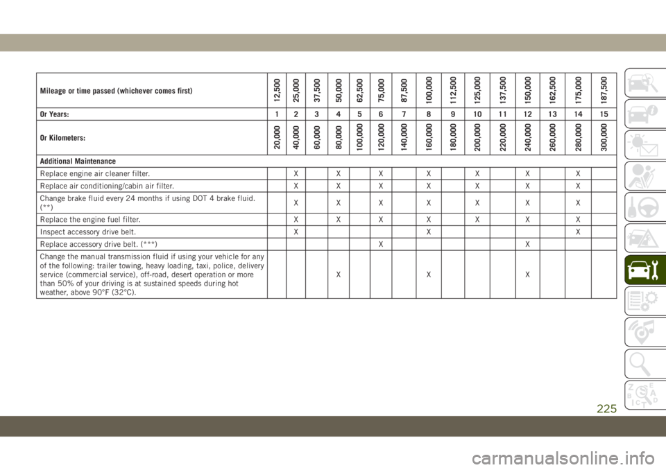
Additional Maintenance
Replace engine air cleaner filter. X X X X X X X
Replace air conditioning/cabin air filter. X X X X X X X
Change brake fluid every 24 months if using DOT 4 brake fluid.
(**)XXX X X X X
Replace the engine fuel filter. X X X X X X X
Inspect accessory drive belt. X X X
Replace accessory drive belt. (***) X X
Change the manual transmission fluid if using your vehicle for any
of the following: trailer towing, heavy loading, taxi, police, delivery
service (commercial service), off-road, desert operation or more
than 50% of your driving is at sustained speeds during hot
weather, above 90°F (32°C).XX X
225
Page 234 of 344
WARNING!
matically and may start at any time,
whether the engine is running or not.
• When working near the radiator cooling
fan, turn the ignition to the OFF mode.
The fan is temperature controlled and
can start at any time the ignition is in the
ON mode.
Engine Coolant Checks
Check the engine coolant (antifreeze) protec-
tion every 12 months (before the onset of
freezing weather, where applicable). If the
engine coolant (antifreeze) is dirty, the sys-
tem should be drained, flushed, and refilled
with fresh OAT coolant (conforming to
MS.90032) by an authorized dealer. Check
the front of the A/C condenser for any accu-
mulation of bugs, leaves, etc. If dirty, clean
by gently spraying water from a garden hose
vertically down the face of the condenser.
Check the engine cooling system hoses for
brittle rubber, cracking, tears, cuts, and
tightness of the connection at the coolant
recovery bottle and radiator. Inspect the en-tire system for leaks. DO NOT REMOVE THE
COOLANT PRESSURE CAP WHEN THE
COOLING SYSTEM IS HOT.
Adding Washer Fluid
The windshield and rear window washers
share the same fluid reservoir. The fluid res-
ervoir is located in the front of the engine
compartment. Be sure to check the fluid level
in the reservoir at regular intervals. Fill the
reservoir with windshield washer solvent (not
radiator antifreeze) and operate the system
for a few seconds to flush out the residual
water.
When refilling the washer fluid reservoir, take
some washer fluid and apply it to a cloth or
towel and wipe clean the wiper blades, this
will help blade performance.
To prevent freeze-up of your windshield
washer system in cold weather, select a solu-
tion or mixture that meets or exceeds the
temperature range of your climate. This rat-
ing information can be found on most washer
fluid containers.
WARNING!
Commercially available windshield washer
solvents are flammable. They could ignite
and burn you. Care must be exercised
when filling or working around the washer
solution.
CAUTION!
Do not travel with the windshield washer
fluid reservoir empty: the windshield
washer is essential for improving visibility.
Repeated operation of the system without
fluid could damage or cause rapid deterio-
ration of some system components.
Brake System
In order to assure brake system performance,
all brake system components should be in-
spected periodically. Refer to the “Mainte-
nance Plan” in this section for the proper
maintenance intervals.
SERVICING AND MAINTENANCE
232
Page 238 of 344
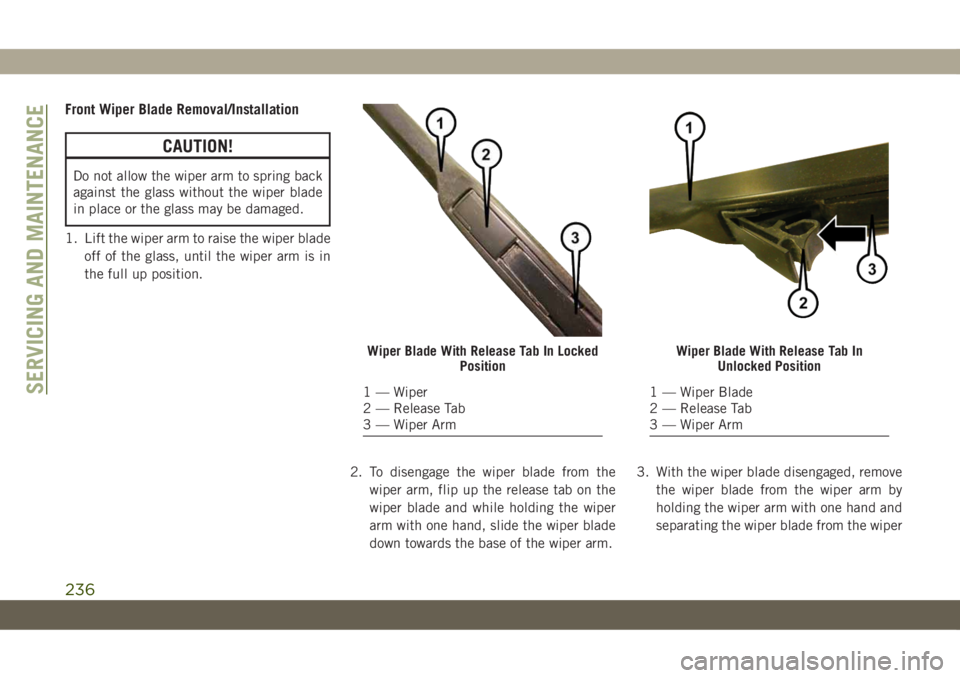
Front Wiper Blade Removal/Installation
CAUTION!
Do not allow the wiper arm to spring back
against the glass without the wiper blade
in place or the glass may be damaged.
1. Lift the wiper arm to raise the wiper blade
off of the glass, until the wiper arm is in
the full up position.
2. To disengage the wiper blade from the
wiper arm, flip up the release tab on the
wiper blade and while holding the wiper
arm with one hand, slide the wiper blade
down towards the base of the wiper arm.3. With the wiper blade disengaged, remove
the wiper blade from the wiper arm by
holding the wiper arm with one hand and
separating the wiper blade from the wiper
Wiper Blade With Release Tab In Locked
Position
1 — Wiper
2 — Release Tab
3 — Wiper Arm
Wiper Blade With Release Tab In
Unlocked Position
1 — Wiper Blade
2 — Release Tab
3 — Wiper ArmSERVICING AND MAINTENANCE
236