start stop button JEEP CHEROKEE 2019 Owner handbook (in English)
[x] Cancel search | Manufacturer: JEEP, Model Year: 2019, Model line: CHEROKEE, Model: JEEP CHEROKEE 2019Pages: 344, PDF Size: 6.35 MB
Page 15 of 344
KEYS
Key Fob
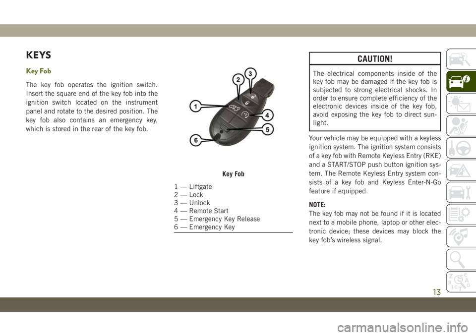
The key fob operates the ignition switch.
Insert the square end of the key fob into the
ignition switch located on the instrument
panel and rotate to the desired position. The
key fob also contains an emergency key,
which is stored in the rear of the key fob.
CAUTION!
The electrical components inside of the
key fob may be damaged if the key fob is
subjected to strong electrical shocks. In
order to ensure complete efficiency of the
electronic devices inside of the key fob,
avoid exposing the key fob to direct sun-
light.
Your vehicle may be equipped with a keyless
ignition system. The ignition system consists
of a key fob with Remote Keyless Entry (RKE)
and a START/STOP push button ignition sys-
tem. The Remote Keyless Entry system con-
sists of a key fob and Keyless Enter-N-Go
feature if equipped.
NOTE:
The key fob may not be found if it is located
next to a mobile phone, laptop or other elec-
tronic device; these devices may block the
key fob’s wireless signal.
Key Fob
1 — Liftgate
2 — Lock
3 — Unlock
4 — Remote Start
5 — Emergency Key Release
6 — Emergency Key
13
Page 16 of 344
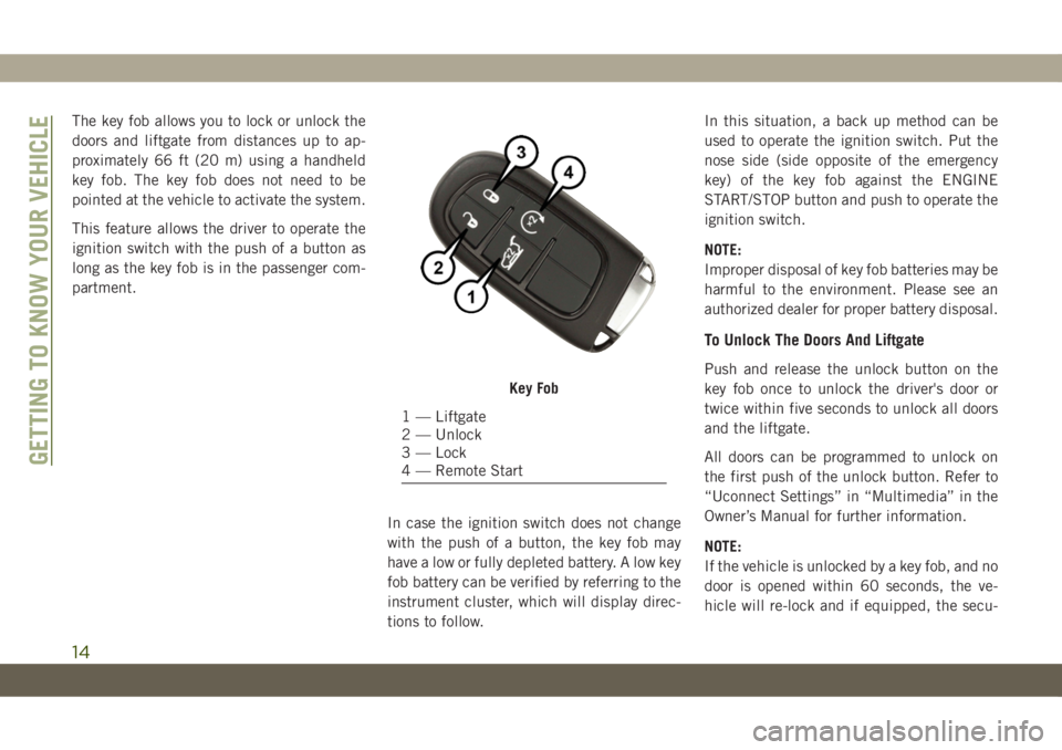
The key fob allows you to lock or unlock the
doors and liftgate from distances up to ap-
proximately 66 ft (20 m) using a handheld
key fob. The key fob does not need to be
pointed at the vehicle to activate the system.
This feature allows the driver to operate the
ignition switch with the push of a button as
long as the key fob is in the passenger com-
partment.
In case the ignition switch does not change
with the push of a button, the key fob may
have a low or fully depleted battery. A low key
fob battery can be verified by referring to the
instrument cluster, which will display direc-
tions to follow.In this situation, a back up method can be
used to operate the ignition switch. Put the
nose side (side opposite of the emergency
key) of the key fob against the ENGINE
START/STOP button and push to operate the
ignition switch.
NOTE:
Improper disposal of key fob batteries may be
harmful to the environment. Please see an
authorized dealer for proper battery disposal.
To Unlock The Doors And Liftgate
Push and release the unlock button on the
key fob once to unlock the driver's door or
twice within five seconds to unlock all doors
and the liftgate.
All doors can be programmed to unlock on
the first push of the unlock button. Refer to
“Uconnect Settings” in “Multimedia” in the
Owner’s Manual for further information.
NOTE:
If the vehicle is unlocked by a key fob, and no
door is opened within 60 seconds, the ve-
hicle will re-lock and if equipped, the secu-
Key Fob
1 — Liftgate
2 — Unlock
3 — Lock
4 — Remote Start
GETTING TO KNOW YOUR VEHICLE
14
Page 18 of 344
WARNING!
Never remove the mechanical key while
the vehicle is moving, as the steering
wheel will automatically lock as soon as
WARNING!
the key is turned. This also applies to
vehicles that are being towed.
Keyless Enter-N-Go (Ignition) — If
Equipped
This feature allows the driver to operate the
ignition switch with the push of a button as
long as the key fob is in the passenger com-
partment.
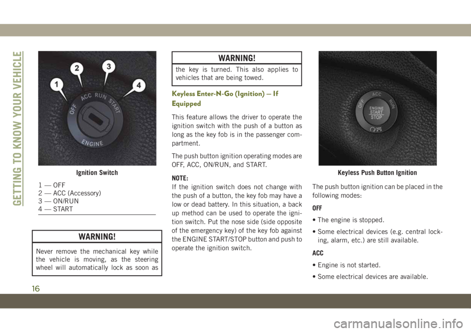
The push button ignition operating modes are
OFF, ACC, ON/RUN, and START.
NOTE:
If the ignition switch does not change with
the push of a button, the key fob may have a
low or dead battery. In this situation, a back
up method can be used to operate the igni-
tion switch. Put the nose side (side opposite
of the emergency key) of the key fob against
the ENGINE START/STOP button and push to
operate the ignition switch.The push button ignition can be placed in the
following modes:
OFF
• The engine is stopped.
• Some electrical devices (e.g. central lock-
ing, alarm, etc.) are still available.
ACC
• Engine is not started.
• Some electrical devices are available.
Ignition Switch
1 — OFF
2 — ACC (Accessory)
3 — ON/RUN
4—START
Keyless Push Button Ignition
GETTING TO KNOW YOUR VEHICLE
16
Page 19 of 344
ON/RUN
• Driving position.
• All the electrical devices are available.
START
• Start the engine.
NOTE:
The vehicle will not start if the key fob is
located inside the cargo area and the liftgate
is opened.
WARNING!
• When exiting the vehicle, always remove
the key fob from the vehicle and lock
your vehicle.
• Never leave children alone in a vehicle,
or with access to an unlocked vehicle.
• Allowing children to be in a vehicle un-
attended is dangerous for a number of
reasons. A child or others could be seri-
ously or fatally injured. Children should
be warned not to touch the parking
brake, brake pedal or the gear selector.
• Do not leave the key fob in or near the
vehicle, or in a location accessible to
WARNING!
children, and do not leave the ignition of
a vehicle equipped with Keyless Enter-
N-Go in the ON/RUN mode. A child
could operate power windows, other con-
trols, or move the vehicle.
• Do not leave children or animals inside
parked vehicles in hot weather. Interior
heat build-up may cause serious injury
or death.
CAUTION!
An unlocked vehicle is an invitation for
thieves. Always remove key fob from the
vehicle and lock all doors when leaving the
vehicle unattended.
NOTE:
For further information, refer to "Starting The
Engine" in "Starting And Operating."
REMOTE STARTING
SYSTEM — IF EQUIPPED
Push the remote start button on the key fob
twice within five seconds. Pushing the re-
mote start button a third time shuts the
engine off.
To drive the vehicle, push the START/STOP
button to turn the ignition to the ON/RUN
mode.
NOTE:
• With remote start, the engine will only run
for 15 minutes (timeout) unless the igni-
tion is placed in the ON/RUN mode.
• The vehicle must be started with the key
after two consecutive timeouts.
How To Use Remote Start
Push the remote start button on the key fob
twice within five seconds. Pushing the re-
mote start button a third time shuts the
engine off.
17
Page 20 of 344
To drive the vehicle, push the unlock button,
insert the key in the ignition and turn to the
ON/RUN position.
NOTE:
• With remote start, the engine will only run
for 15 minutes (timeout) unless the igni-
tion key is placed in the ON/RUN position.
• The vehicle must be started with the key
after two consecutive timeouts.
All of the following conditions must be met
before the engine will remote start:
• Gear selector in PARK
• Doors closed
• Hood closed
• Liftgate closed
• Hazard switch off
• Brake switch inactive (brake pedal not
pushed)
• Battery at an acceptable charge level
• Check engine light shall not be present• System not disabled from previous remote
start event
• Vehicle alarm system indicator flashing
• Ignition in STOP/OFF position
• Fuel level meets minimum requirement
• Vehicle security alarm is not signaling an
intrusion
WARNING!
• Do not start or run an engine in a closed
garage or confined area. Exhaust gas
contains Carbon Monoxide (CO) which is
odorless and colorless. Carbon Monox-
ide is poisonous and can cause serious
injury or death when inhaled.
• Keep key fobs away from children. Op-
eration of the Remote Start System, win-
dows, door locks or other controls could
cause serious injury or death.
To Enter Remote Start Mode
Push and release the remote start button on
the key fob twice within five seconds. The
vehicle doors will lock, the parking lights will
flash, and the horn will chirp twice (if pro-
grammed). Then, the engine will start, and
the vehicle will remain in the Remote Start
mode for a 15-minute cycle.
NOTE:
• If an engine fault is present or fuel level is
low, the vehicle will start and then shut
down in 10 seconds.
• The park lamps will turn on and remain on
during Remote Start mode.
• For security, power window and power sun-
roof operation (if equipped) are disabled
when the vehicle is in the Remote Start
mode.
• The engine can be started two consecutive
times with the key fob. However, the igni-
tion must be cycled by pushing the START/
STOP button twice (or the ignition switch
must be cycled to the ON/RUN position)
before you can repeat the start sequence
for a third cycle.
GETTING TO KNOW YOUR VEHICLE
18
Page 64 of 344
INSTRUMENT CLUSTER
DISPLAY
Your vehicle may be equipped with an instru-
ment cluster display, which offers useful in-
formation to the driver. With the ignition in
the STOP/OFF mode, opening/closing of a
door will activate the display for viewing, and
display the total miles, or kilometers, in the
odometer. Your instrument cluster display is
designed to display important information
about your vehicle’s systems and features.
Using a driver interactive display located on
the instrument panel, your instrument clus-
ter display can show you how systems are
working and give you warnings when they
aren’t. The steering wheel mounted controls
allow you to scroll through and enter the main
menus and submenus. You can access the
specific information you want and make se-
lections and adjustments.
Instrument Cluster Display Location And
Controls
The instrument cluster display features a
driver-interactive display that is located in
the instrument cluster.
The instrument cluster display menu items
consist of the following:
• Speedometer
• Vehicle Info
• Driver Assist — If Equipped
• Fuel Economy
• Trip Info
• Stop/Start
• Audio
• Messages
• Screen Setup
• Speed WarningThe system allows the driver to select infor-
mation by pushing the following buttons
mounted on the steering wheel:
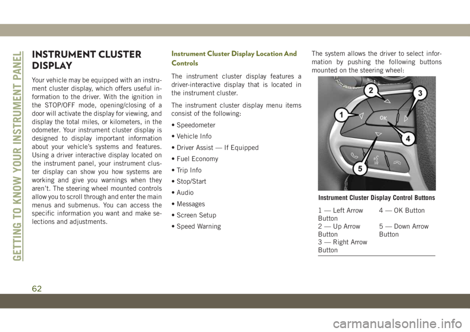
Instrument Cluster Display Control Buttons
1 — Left Arrow
Button4 — OK Button
2 — Up Arrow
Button5 — Down Arrow
Button
3 — Right Arrow
Button
GETTING TO KNOW YOUR INSTRUMENT PANEL
62
Page 65 of 344
•Up Arrow Button
Push and release theuparrow button to
scroll upward through the main menu and
submenus.
•Down Arrow Button
Push and release thedownarrow button to
scroll downward through the main menu
and submenus.
•Right Arrow Button
Push and release therightarrow button to
access the information screens or submenu
screens of a main menu item.
•Left Arrow Button
Push and release theleftarrow button to
access the information screens or submenu
screens of a main menu item.
•OK Button
Push theOKbutton to access/select the
information screens or submenu screens of
a main menu item. Push and hold theOK
button to reset displayed/selected features
that can be reset.Instrument Cluster Display Selectable
Items
The instrument cluster display can be used to
view the following main menu items:
Speedometer Stop/Start
Vehicle Info Audio
Driver Assist Messages
Fuel Economy Screen Setup
Trip Gear Shift Indicator
(GSI)
NOTE:
Depending on the vehicles options, feature
settings may vary. Refer to the “Instrument
Cluster Display” in “Getting To know Your
Instrument Panel” in the Owner’s Manual for
further information.
Diesel Displays
When the appropriate conditions exist, the
following messages display in the instrument
cluster display:
• Exhaust Filter Nearing Full Safely Drive at
Consistent Speeds to Clear• Exhaust Filter Full – Power Reduced See
Dealer
• Exhaust System Service Required – See
Dealer
• Exhaust System – Filter XX% Full Service
Required See Dealer
• Exhaust System Regeneration in Process
Continue Driving
• Exhaust System – Regeneration Completed
Diesel Particulate Filter (DPF) Messages
This engine meets all required diesel engine
emissions standards. To achieve these emis-
sions standards, your vehicle is equipped
with a state-of-the-art engine and exhaust
system. These systems are seamlessly inte-
grated into your vehicle and managed by the
Powertrain Control Module (PCM). The PCM
manages engine combustion to allow the ex-
haust system’s catalyst to trap and burn Par-
ticulate Matter (PM) pollutants, with no input
or interaction on your part.
63
Page 143 of 344
Normal Starting Procedure — Keyless
Enter-N-Go
Observe the instrument panel cluster lights
when starting the engine.
NOTE:
Normal starting of either a cold or a warm
engine is obtained without pumping or press-
ing the accelerator pedal.
1. Always apply the parking brake.
2. Press and hold the brake pedal while
pushing the ENGINE START/STOP button
once.
NOTE:
A delay of the start of up to five seconds is
possible under very cold conditions. The
“Wait to Start” telltale will be illuminated
during the pre-heat process, When the
engine Wait To Start light goes off the
engine will automatically crank.
CAUTION!
If the “Water in Fuel Indicator Light” re-
mains on, DO NOT START the engine be-
CAUTION!
fore the water is drained from the fuel
filters to avoid engine damage.
3. The system will automatically engage the
starter to crank the engine. If the vehicle
fails to start, the starter will disengage
automatically after 30 seconds.
4. If you wish to stop the cranking of the
engine prior to the engine starting, push
the button again.
5. Check that the oil pressure warning light
has turned off.
6. Release the parking brake.
Engine Warm Up
Avoid full throttle operation when the engine
is cold. When starting a cold engine, bring the
engine up to operating speed slowly to allow
the oil pressure to stabilize as the engine
warms up.NOTE:
High-speed, no-load running of a cold engine
can result in excessive white smoke and poor
engine performance. No-load engine speeds
should be kept under 1,200 RPM during the
warm-up period, especially in cold ambient
temperature conditions.
ENGINE BREAK-IN
RECOMMENDATIONS
A long break-in period is not required for the
engine and drivetrain (transmission and axle)
in your vehicle.
Drive moderately during the first 300 miles
(500 km). After the initial 60 miles
(100 km), speeds up to 50 or 55 mph (80 or
90 km/h) are desirable.
While cruising, brief full-throttle acceleration
within the limits of local traffic laws contrib-
utes to a good break-in. Wide-open throttle
acceleration in low gear can be detrimental
and should be avoided.
141
Page 150 of 344
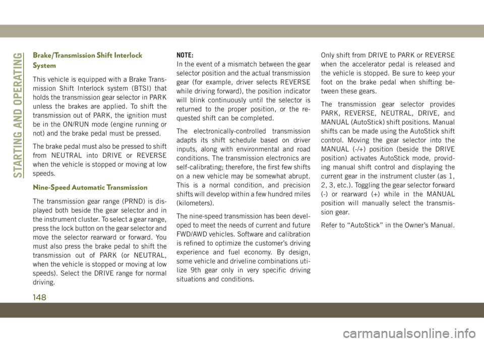
Brake/Transmission Shift Interlock
System
This vehicle is equipped with a Brake Trans-
mission Shift Interlock system (BTSI) that
holds the transmission gear selector in PARK
unless the brakes are applied. To shift the
transmission out of PARK, the ignition must
be in the ON/RUN mode (engine running or
not) and the brake pedal must be pressed.
The brake pedal must also be pressed to shift
from NEUTRAL into DRIVE or REVERSE
when the vehicle is stopped or moving at low
speeds.
Nine-Speed Automatic Transmission
The transmission gear range (PRND) is dis-
played both beside the gear selector and in
the instrument cluster. To select a gear range,
press the lock button on the gear selector and
move the selector rearward or forward. You
must also press the brake pedal to shift the
transmission out of PARK (or NEUTRAL,
when the vehicle is stopped or moving at low
speeds). Select the DRIVE range for normal
driving.NOTE:
In the event of a mismatch between the gear
selector position and the actual transmission
gear (for example, driver selects REVERSE
while driving forward), the position indicator
will blink continuously until the selector is
returned to the proper position, or the re-
quested shift can be completed.
The electronically-controlled transmission
adapts its shift schedule based on driver
inputs, along with environmental and road
conditions. The transmission electronics are
self-calibrating; therefore, the first few shifts
on a new vehicle may be somewhat abrupt.
This is a normal condition, and precision
shifts will develop within a few hundred miles
(kilometers).
The nine-speed transmission has been devel-
oped to meet the needs of current and future
FWD/AWD vehicles. Software and calibration
is refined to optimize the customer’s driving
experience and fuel economy. By design,
some vehicle and driveline combinations uti-
lize 9th gear only in very specific driving
situations and conditions.Only shift from DRIVE to PARK or REVERSE
when the accelerator pedal is released and
the vehicle is stopped. Be sure to keep your
foot on the brake pedal when shifting be-
tween these gears.
The transmission gear selector provides
PARK, REVERSE, NEUTRAL, DRIVE, and
MANUAL (AutoStick) shift positions. Manual
shifts can be made using the AutoStick shift
control. Moving the gear selector into the
MANUAL (-/+) position (beside the DRIVE
position) activates AutoStick mode, provid-
ing manual shift control and displaying the
current gear in the instrument cluster (as 1,
2, 3, etc.). Toggling the gear selector forward
(-) or rearward (+) while in the MANUAL
position will manually select the transmis-
sion gear.
Refer to “AutoStick” in the Owner’s Manual.
STARTING AND OPERATING
148
Page 155 of 344
Shifting Out Of 4X4 LOW
With the vehicle at speeds of 0 to 3 mph (0 to
5 km/h), the ignition in the ON mode and the
engine running, shift the transmission into
NEUTRAL, and push the “4WD LOW” button
once. The “4WD LOW” indicator light in the
instrument cluster will flash and go out when
the shift is complete.
NOTE:
• If shift conditions/interlocks are not met, a
message will flash from the instrument
cluster display with instructions on how to
complete the requested shift. Refer to “In-
strument Cluster Display” in “Getting To
Know Your Instrument Panel” for further
information.
• Shifting into or out of 4WD LOW is possible
with the vehicle completely stopped; how-
ever, difficulty may occur due to the mating
clutch teeth not being properly aligned.
Several attempts may be required for
clutch teeth alignment and shift comple-
tion to occur. The preferred method is with
the vehicle rolling 0 to 3 mph (0 to 5 km/h).If the vehicle is moving faster than 3 mph
(5 km/h), the 4WD system will not allow the
shift.
NEUTRAL Shift Procedure
WARNING!
You or others could be injured or killed if
you leave the vehicle unattended with the
power transfer unit in the NEUTRAL (N)
position without first fully engaging the
parking brake. The NEUTRAL (N) position
disengages both the front and rear drive-
shafts from the powertrain and will allow
the vehicle to roll, even if the automatic
transmission is in PARK (or manual trans-
mission is in gear). The parking brake
should always be applied when the driver
is not in the vehicle.
1. Bring the vehicle to a complete stop on
level ground and shift the automatic
transmission to PARK
2. Turn the engine OFF.
3. Turn the ignition to the ON/RUN mode,
but do not start the engine.
4. Press and hold the brake pedal.5. Shift the transmission into NEUTRAL.
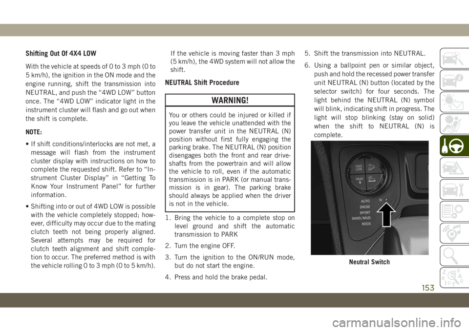
6. Using a ballpoint pen or similar object,
push and hold the recessed power transfer
unit NEUTRAL (N) button (located by the
selector switch) for four seconds. The
light behind the NEUTRAL (N) symbol
will blink, indicating shift in progress. The
light will stop blinking (stay on solid)
when the shift to NEUTRAL (N) is
complete.
Neutral Switch
153