buttons JEEP CHEROKEE 2023 User Guide
[x] Cancel search | Manufacturer: JEEP, Model Year: 2023, Model line: CHEROKEE, Model: JEEP CHEROKEE 2023Pages: 276, PDF Size: 12.55 MB
Page 66 of 276
64GETTING TO KNOW YOUR INSTRUMENT PANEL
The instrument cluster display menu items may consist of
the following:
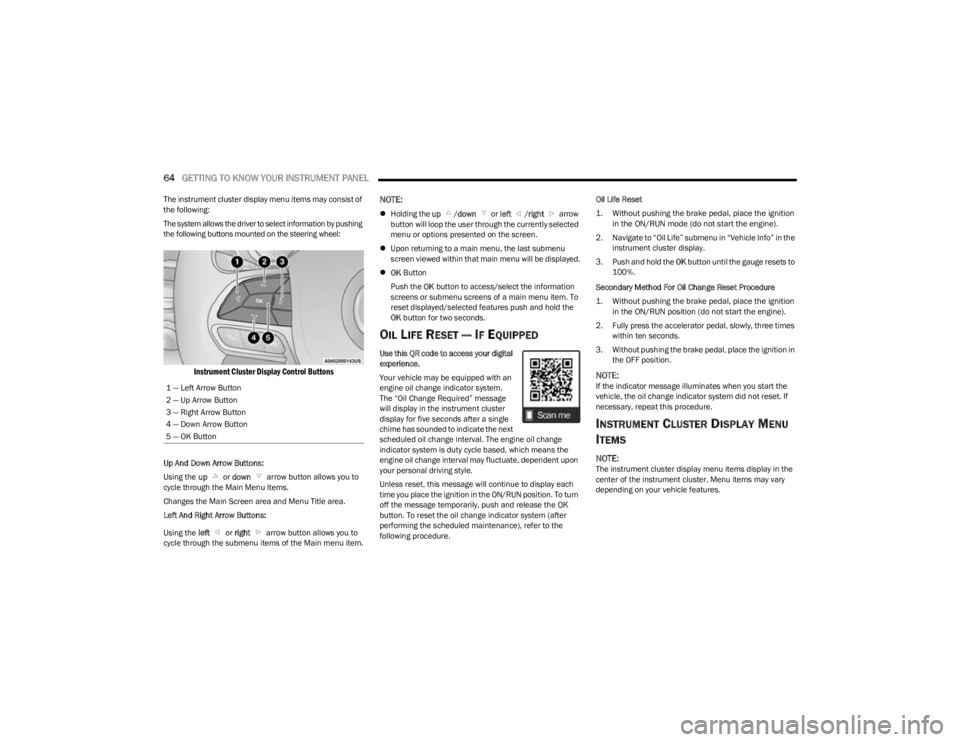
The system allows the driver to select information by pushing
the following buttons mounted on the steering wheel:
Instrument Cluster Display Control Buttons
Up And Down Arrow Buttons:
Using the up or down arrow button allows you to
cycle through the Main Menu Items.
Changes the Main Screen area and Menu Title area.
Left And Right Arrow Buttons:
Using the left or right arrow button allows you to
cycle through the submenu items of the Main menu item.
NOTE:
Holding the up /down or left /right arrow
button will loop the user through the currently selected
menu or options presented on the screen.
Upon returning to a main menu, the last submenu
screen viewed within that main menu will be displayed.
OK Button
Push the OK button to access/select the information
screens or submenu screens of a main menu item. To
reset displayed/selected features push and hold the
OK button for two seconds.
OIL LIFE RESET — IF EQUIPPED
Use this QR code to access your digital
experience.
Your vehicle may be equipped with an
engine oil change indicator system.
The “Oil Change Required” message
will display in the instrument cluster
display for five seconds after a single
chime has sounded to indicate the next
scheduled oil change interval. The engine oil change
indicator system is duty cycle based, which means the
engine oil change interval may fluctuate, dependent upon
your personal driving style.
Unless reset, this message will continue to display each
time you place the ignition in the ON/RUN position. To turn
off the message temporarily, push and release the OK
button. To reset the oil change indicator system (after
performing the scheduled maintenance), refer to the
following procedure. Oil Life Reset
1. Without pushing the brake pedal, place the ignition
in the ON/RUN mode (do not start the engine).
2. Navigate to “Oil Life” submenu in “Vehicle Info” in the instrument cluster display.
3. Push and hold the OK button until the gauge resets to
100%.
Secondary Method For Oil Change Reset Procedure
1. Without pushing the brake pedal, place the ignition in the ON/RUN position (do not start the engine).
2. Fully press the accelerator pedal, slowly, three times within ten seconds.
3. Without pushing the brake pedal, place the ignition in the OFF position.
NOTE:If the indicator message illuminates when you start the
vehicle, the oil change indicator system did not reset. If
necessary, repeat this procedure.
INSTRUMENT CLUSTER DISPLAY MENU
I
TEMS
NOTE:The instrument cluster display menu items display in the
center of the instrument cluster. Menu items may vary
depending on your vehicle features.
1 — Left Arrow Button
2 — Up Arrow Button
3 — Right Arrow Button
4 — Down Arrow Button
5 — OK Button
23_KL_OM_EN_USC_t.book Page 64
Page 88 of 276
86STARTING AND OPERATING
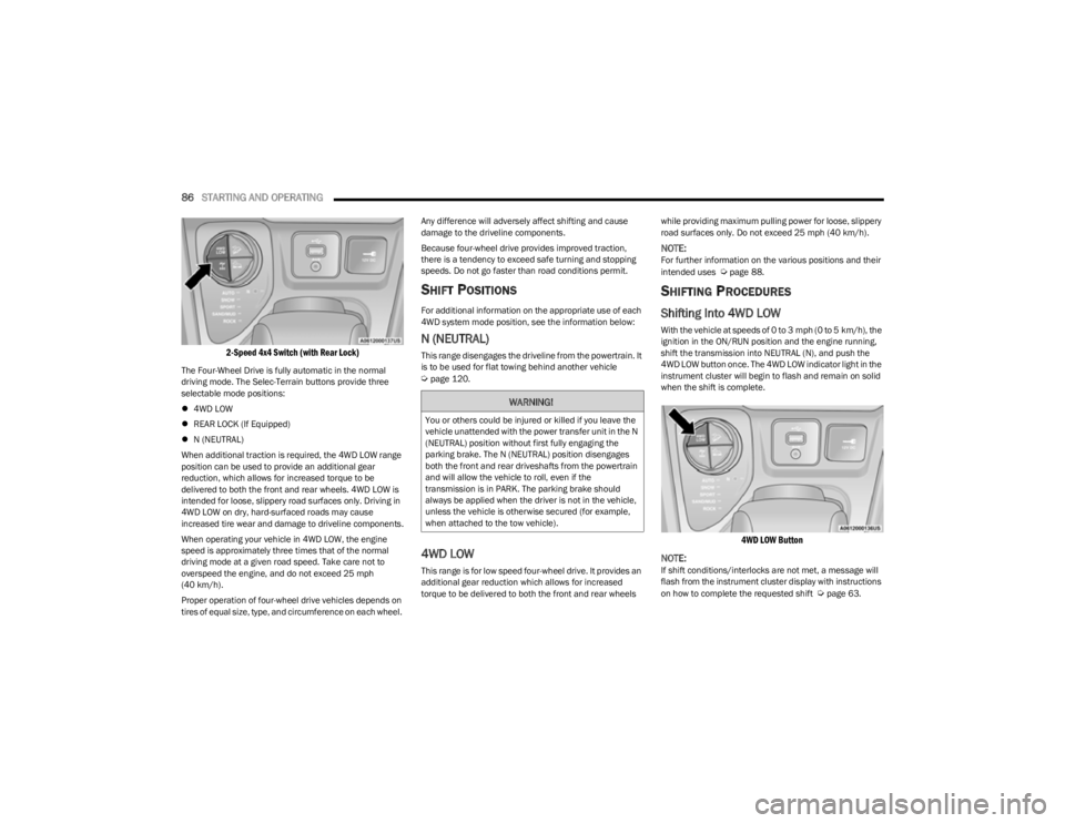
2-Speed 4x4 Switch (with Rear Lock)
The Four-Wheel Drive is fully automatic in the normal
driving mode. The Selec-Terrain buttons provide three
selectable mode positions:
4WD LOW
REAR LOCK (If Equipped)
N (NEUTRAL)
When additional traction is required, the 4WD LOW range
position can be used to provide an additional gear
reduction, which allows for increased torque to be
delivered to both the front and rear wheels. 4WD LOW is
intended for loose, slippery road surfaces only. Driving in
4WD LOW on dry, hard-surfaced roads may cause
increased tire wear and damage to driveline components.
When operating your vehicle in 4WD LOW, the engine
speed is approximately three times that of the normal
driving mode at a given road speed. Take care not to
overspeed the engine, and do not exceed 25 mph
(40 km/h).
Proper operation of four-wheel drive vehicles depends on
tires of equal size, type, and circumference on each wheel. Any difference will adversely affect shifting and cause
damage to the driveline components.
Because four-wheel drive provides improved traction,
there is a tendency to exceed safe turning and stopping
speeds. Do not go faster than road conditions permit.
SHIFT POSITIONS
For additional information on the appropriate use of each
4WD system mode position, see the information below:
N (NEUTRAL)
This range disengages the driveline from the powertrain. It
is to be used for flat towing behind another vehicle
Úpage 120.
4WD LOW
This range is for low speed four-wheel drive. It provides an
additional gear reduction which allows for increased
torque to be delivered to both the front and rear wheels
while providing maximum pulling power for loose, slippery
road surfaces only. Do not exceed 25 mph (40 km/h).
NOTE:For further information on the various positions and their
intended uses Úpage 88.
SHIFTING PROCEDURES
Shifting Into 4WD LOW
With the vehicle at speeds of 0 to 3 mph (0 to 5 km/h), the
ignition in the ON/RUN position and the engine running,
shift the transmission into NEUTRAL (N), and push the
4WD LOW button once. The 4WD LOW indicator light in the
instrument cluster will begin to flash and remain on solid
when the shift is complete.
4WD LOW Button
NOTE:
If shift conditions/interlocks are not met, a message will
flash from the instrument cluster display with instructions
on how to complete the requested shift
Úpage 63.
WARNING!
You or others could be injured or killed if you leave the
vehicle unattended with the power transfer unit in the N
(NEUTRAL) position without first fully engaging the
parking brake. The N (NEUTRAL) position disengages
both the front and rear driveshafts from the powertrain
and will allow the vehicle to roll, even if the
transmission is in PARK. The parking brake should
always be applied when the driver is not in the vehicle,
unless the vehicle is otherwise secured (for example,
when attached to the tow vehicle).
23_KL_OM_EN_USC_t.book Page 86
Page 92 of 276
90STARTING AND OPERATING
Conditions That Force An Application Of The Electric Park
Brake While In Autostop Mode:
The driver’s door is open and brake pedal released
The driver’s door is open and the driver’s seat belt is
unbuckled
The engine hood has been opened
A Stop/Start system error occurs
If the Electric Park Brake (EPB) is applied with the engine
off, the engine may require a manual restart and the EPB
may require a manual release (press brake pedal and
push EPB switch).
TO MANUALLY TURN OFF THE STOP/
S
TART SYSTEM
Stop/Start OFF Switch
Push the Stop/Start OFF switch (located on the switch
bank). The light on the switch will illuminate. The “STOP/
START OFF” message will appear in the instrument cluster
display and the Autostop mode will be disabled
Úpage 63.
NOTE:The Stop/Start system will reset itself back to the ON
mode every time the ignition is turned OFF and back ON.
TO MANUALLY TURN ON THE STOP/
S
TART SYSTEM
Push the Stop/Start OFF switch (located on the switch
bank). The light on the switch will turn off.
SYSTEM MALFUNCTION
If there is a malfunction in the Stop/Start system, the
system will not shut down the engine. A “SERVICE STOP/
START SYSTEM” message and a yellow Stop/Start telltale
will appear in the instrument cluster display
Úpage 68.
If the “SERVICE STOP/START SYSTEM” message appears
in the instrument cluster display, have the system
checked by an authorized dealer.
CRUISE CONTROL SYSTEMS — IF EQUIPPED
Your vehicle may be equipped with the Cruise Control
system, or the Adaptive Cruise Control (ACC) system:
Cruise Control will keep your vehicle at a constant
preset speed.
Adaptive Cruise Control (ACC) will adjust the vehicle
speed up to the preset speed to maintain a distance
with the vehicle ahead.
NOTE:
In vehicles equipped with ACC, if ACC is not enabled,
Fixed Speed Cruise Control will not detect vehicles
directly ahead of you. Always be aware of the feature
selected.
Only one Cruise Control feature can operate at a time.
For example, if Fixed Speed Cruise Control is enabled,
Adaptive Cruise Control will be unavailable, and vice
versa.
CRUISE CONTROL
When engaged, the Cruise Control takes over accelerator
operations at speeds greater than 20 mph (32 km/h).
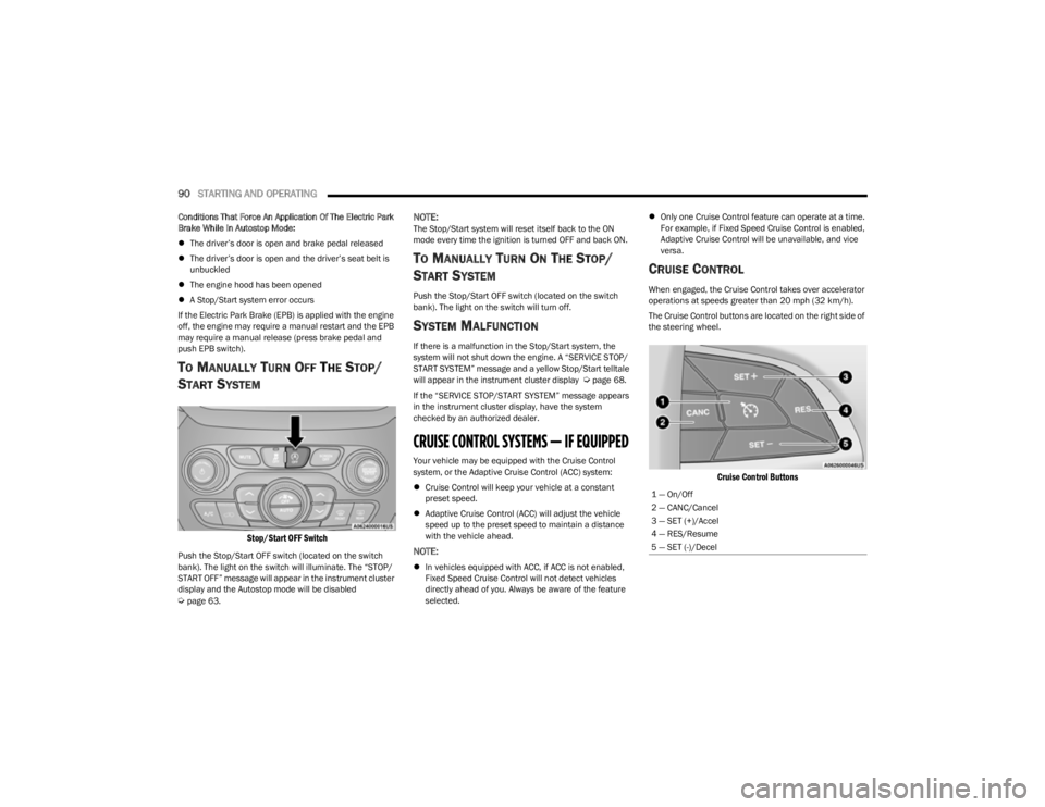
The Cruise Control buttons are located on the right side of
the steering wheel.
Cruise Control Buttons
1 — On/Off
2 — CANC/Cancel
3 — SET (+)/Accel
4 — RES/Resume
5 — SET (-)/Decel
23_KL_OM_EN_USC_t.book Page 90
Page 95 of 276
STARTING AND OPERATING93
Adaptive Cruise Control (ACC) Operation
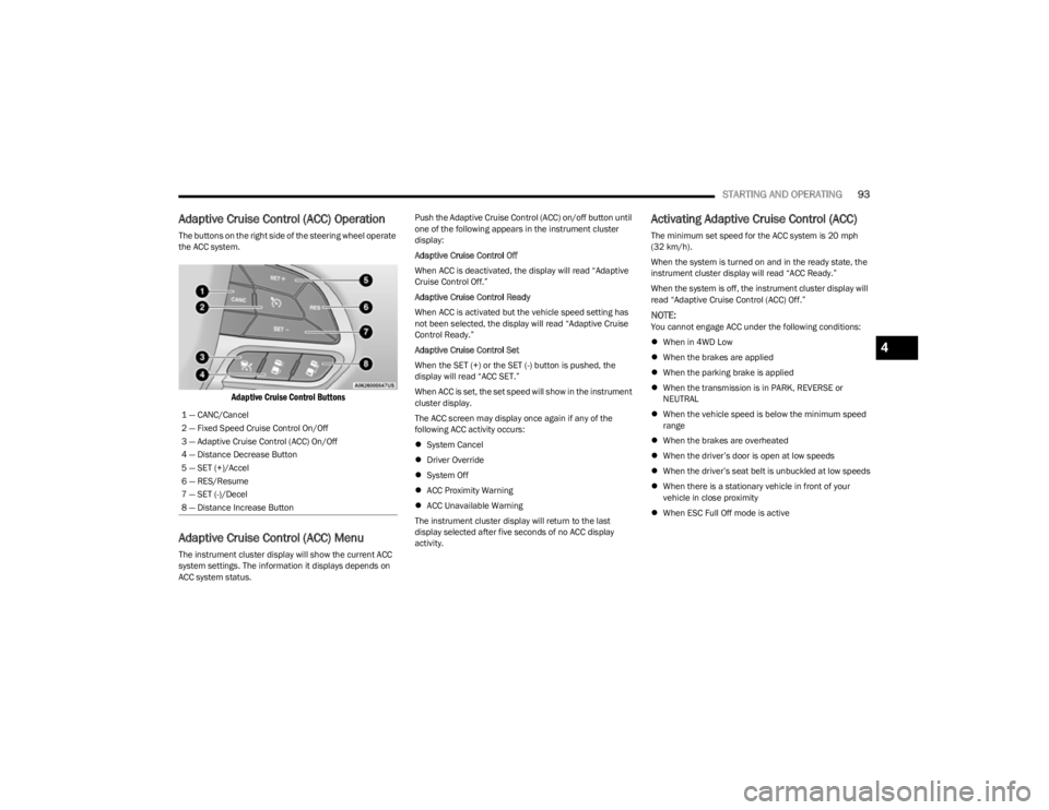
The buttons on the right side of the steering wheel operate
the ACC system.
Adaptive Cruise Control Buttons
Adaptive Cruise Control (ACC) Menu
The instrument cluster display will show the current ACC
system settings. The information it displays depends on
ACC system status. Push the Adaptive Cruise Control (ACC) on/off button until
one of the following appears in the instrument cluster
display:
Adaptive Cruise Control Off
When ACC is deactivated, the display will read “Adaptive
Cruise Control Off.”
Adaptive Cruise Control Ready
When ACC is activated but the vehicle speed setting has
not been selected, the display will read “Adaptive Cruise
Control Ready.”
Adaptive Cruise Control Set
When the SET (+) or the SET (-) button is pushed, the
display will read “ACC SET.”
When ACC is set, the set speed will show in the instrument
cluster display.
The ACC screen may display once again if any of the
following ACC activity occurs:
System Cancel
Driver Override
System Off
ACC Proximity Warning
ACC Unavailable Warning
The instrument cluster display will return to the last
display selected after five seconds of no ACC display
activity.
Activating Adaptive Cruise Control (ACC)
The minimum set speed for the ACC system is 20 mph
(32 km/h).
When the system is turned on and in the ready state, the
instrument cluster display will read “ACC Ready.”
When the system is off, the instrument cluster display will
read “Adaptive Cruise Control (ACC) Off.”
NOTE:You cannot engage ACC under the following conditions:
When in 4WD Low
When the brakes are applied
When the parking brake is applied
When the transmission is in PARK, REVERSE or
NEUTRAL
When the vehicle speed is below the minimum speed
range
When the brakes are overheated
When the driver’s door is open at low speeds
When the driver’s seat belt is unbuckled at low speeds
When there is a stationary vehicle in front of your
vehicle in close proximity
When ESC Full Off mode is active
1 — CANC/Cancel
2 — Fixed Speed Cruise Control On/Off
3 — Adaptive Cruise Control (ACC) On/Off
4 — Distance Decrease Button
5 — SET (+)/Accel
6 — RES/Resume
7 — SET (-)/Decel
8 — Distance Increase Button
4
23_KL_OM_EN_USC_t.book Page 93
Page 97 of 276
STARTING AND OPERATING95
To Resume
If there is a set speed in memory, push the RES (resume)
button and remove your foot from the accelerator pedal.
The instrument cluster display will show the last set
speed.
Resume can be used at any speed above 20 mph
(32 km/h) when only Fixed Speed Cruise Control is being
used.
Resume can be used at any speed above 0 mph (0 km/h)
when ACC is active.
NOTE:
If your vehicle stays at a standstill for longer than two
seconds, then the driver will either have to push the
RES (resume) button, or apply the accelerator pedal to
reengage the Adaptive Cruise Control (ACC) to the
existing set speed.
ACC cannot be resumed if there is a stationary vehicle
in front of your vehicle in close proximity.
To Vary The Speed Setting
To Increase Or Decrease The Set Speed
After setting a speed, you can increase the set speed by
pushing the SET (+) button, or decrease speed by pushing
the SET (-) button.
U.S. Speed (mph)
Pushing the SET (+), or SET (-) button once will result in
a 1 mph speed adjustment. Each subsequent tap of
the button results in an adjustment of 1 mph.
If the button is continually pushed, the set speed will
continue to adjust in 5 mph increments until the button
is released. The new set speed is reflected in the instru -
ment cluster display.
Metric Speed (km/h)
Pushing the SET (+), or SET (-) button once will result in
a 1 km/h speed adjustment. Each subsequent tap of
the button results in an adjustment of 1 km/h.
If the button is continually pushed, the set speed will
continue to adjust in 10 km/h increments until the
button is released. The new set speed is reflected in
the instrument cluster display.
NOTE:When you override and push the SET (+) button or SET (-)
buttons, the new set speed will be the current speed of the
vehicle. When ACC Is Active
When you use the SET (-) button to decelerate, if the
engine’s braking power does not slow the vehicle suffi -
ciently to reach the set speed, the brake system will
automatically slow the vehicle.
The ACC system decelerates the vehicle to a full stop
when following a vehicle in front. If your vehicle follows
the vehicle in front to a standstill, after two seconds the
driver will either have to push the RES (resume) button,
or apply the accelerator pedal to reengage the ACC to
the existing set speed.
The ACC system maintains set speed when driving
uphill and downhill. However, a slight speed change on
moderate hills is normal. In addition, downshifting may
occur while climbing uphill or descending downhill. This
is normal operation and necessary to maintain set
speed. When driving uphill and downhill, the ACC
system will cancel if the braking temperature exceeds
normal range (overheated).
Setting The Following Distance In ACC
The specified following distance for ACC can be set by
varying the distance setting between four bars (longest),
three bars (long), two bars (medium) and one bar (short).
Using this distance setting and the vehicle speed, ACC
calculates and sets the distance to the vehicle ahead. This
distance setting appears in the instrument cluster display.WARNING!
The Resume function should only be used if traffic and
road conditions permit. Resuming a set speed that is
too high or too low for prevailing traffic and road
conditions could cause the vehicle to accelerate or
decelerate too sharply for safe operation. Failure to
follow these warnings can result in a collision and death
or serious personal injury.
4
23_KL_OM_EN_USC_t.book Page 95
Page 109 of 276
STARTING AND OPERATING107
Vehicle speed is less than 15 mph (25 km/h).
Vehicle is not in 4WD Low (if equipped).
The outer surface and the underside of the front and
rear fascias/bumpers are clean and clear of snow, ice,
mud, dirt or other obstruction.
When pushed, the LED on the ParkSense Active Park
Assist switch will blink momentarily, and then the LED will
turn off if any of the previously described conditions are
not present.
NOTE:If the vehicle is driven above approximately 15 mph
(25 km/h) while searching for a parking space, the
instrument cluster display will instruct the driver to slow
down. If the vehicle is driven above approximately 18 mph
(30 km/h), the system will cancel. The driver must then
reactivate the system by pushing the ParkSense Active
Park Assist switch.
PARALLEL/PERPENDICULAR PARKING
S
PACE ASSISTANCE OPERATION
When the ParkSense Active Park Assist system is enabled
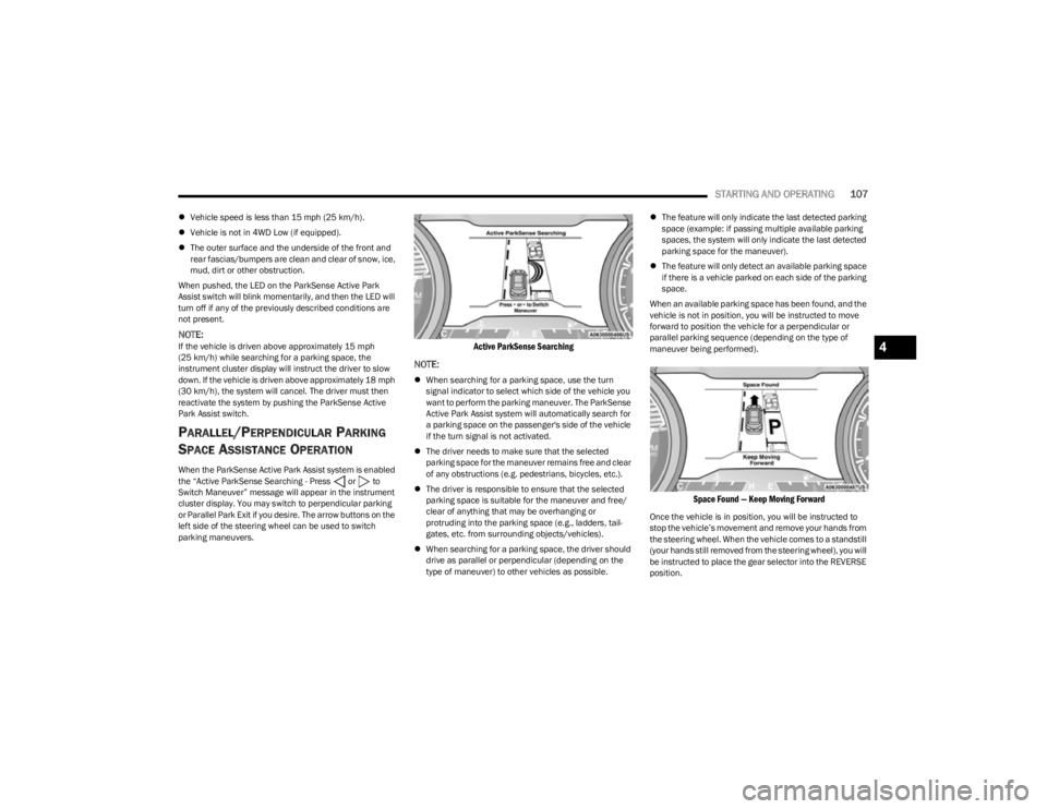
the “Active ParkSense Searching - Press or to
Switch Maneuver” message will appear in the instrument
cluster display. You may switch to perpendicular parking
or Parallel Park Exit if you desire. The arrow buttons on the
left side of the steering wheel can be used to switch
parking maneuvers.
Active ParkSense Searching
NOTE:
When searching for a parking space, use the turn
signal indicator to select which side of the vehicle you
want to perform the parking maneuver. The ParkSense
Active Park Assist system will automatically search for
a parking space on the passenger's side of the vehicle
if the turn signal is not activated.
The driver needs to make sure that the selected
parking space for the maneuver remains free and clear
of any obstructions (e.g. pedestrians, bicycles, etc.).
The driver is responsible to ensure that the selected
parking space is suitable for the maneuver and free/
clear of anything that may be overhanging or
protruding into the parking space (e.g., ladders, tail-
gates, etc. from surrounding objects/vehicles).
When searching for a parking space, the driver should
drive as parallel or perpendicular (depending on the
type of maneuver) to other vehicles as possible.
The feature will only indicate the last detected parking
space (example: if passing multiple available parking
spaces, the system will only indicate the last detected
parking space for the maneuver).
The feature will only detect an available parking space
if there is a vehicle parked on each side of the parking
space.
When an available parking space has been found, and the
vehicle is not in position, you will be instructed to move
forward to position the vehicle for a perpendicular or
parallel parking sequence (depending on the type of
maneuver being performed).
Space Found — Keep Moving Forward
Once the vehicle is in position, you will be instructed to
stop the vehicle’s movement and remove your hands from
the steering wheel. When the vehicle comes to a standstill
(your hands still removed from the steering wheel), you will
be instructed to place the gear selector into the REVERSE
position.
4
23_KL_OM_EN_USC_t.book Page 107
Page 128 of 276
126
MULTIMEDIA
UCONNECT SYSTEMS
For detailed information about your Uconnect 4C/4C NAV
With 8.4-inch Display system, refer to your Uconnect Radio
Instruction Manual.
NOTE:Uconnect screen images are for illustration purposes only
and may not reflect exact software for your vehicle.
CYBERSECURITY
Depending on applicability, your vehicle may be able to
send or receive information from a wired or wireless
network. This information allows systems and features in
your vehicle to function properly.
Your vehicle may be equipped with certain security
features to reduce the risk of unauthorized and unlawful
access to vehicle systems and wireless communications.
Vehicle software technology continues to evolve over time
and FCA US LLC, working with its suppliers, evaluates and
takes appropriate steps as needed. As always, if you
experience unusual behavior, contact an authorized
dealer immediately,
Úpage 258, or refer to your
Uconnect Radio Instruction Manual for additional contact
information. The risk of unauthorized and unlawful access to your
vehicle systems may still exist, even if the most recent
version of vehicle software (such as Uconnect software) is
installed.
NOTE:To help further improve user experience, features,
stability, etc., and minimize the potential risk of a security
breach, vehicle owners should routinely check
www.driveuconnect.com (US Residents) or www.driveuco
-
nnect.ca (Canadian Residents) to learn about available
Uconnect software updates.
UCONNECT SETTINGS
The Uconnect system uses a combination of buttons on
the touchscreen and buttons on the faceplate located on
the center of the instrument panel. These buttons allow
you to access and change the Customer Programmable
Features. Many features can vary by vehicle.
Buttons on the faceplate are located below and/or beside
the Uconnect system in the center of the instrument
panel. In addition, there is a SCROLL/ENTER control knob
located on the right side. Turn the control knob to scroll
through menus and change settings. Push the center of
the control knob one or more times to select or change a
setting.
Your Uconnect system may also have SCREEN OFF and
MUTE buttons on the faceplate.
Push the SCREEN OFF button on the faceplate to turn off
the Uconnect screen. Push the button again or tap the
screen to turn the screen on.
Press the Back Arrow button to exit out of a Menu or
certain option on the Uconnect system.
WARNING!
ONLY insert trusted devices/components into your
vehicle. Media of unknown origin could possibly
contain malicious software, and if installed in your
vehicle, it may increase the possibility for vehicle
systems to be breached.
As always, if you experience unusual vehicle
behavior, take your vehicle to an authorized dealer
immediately.
23_KL_OM_EN_USC_t.book Page 126
Page 129 of 276
MULTIMEDIA127
CUSTOMER PROGRAMMABLE FEATURES
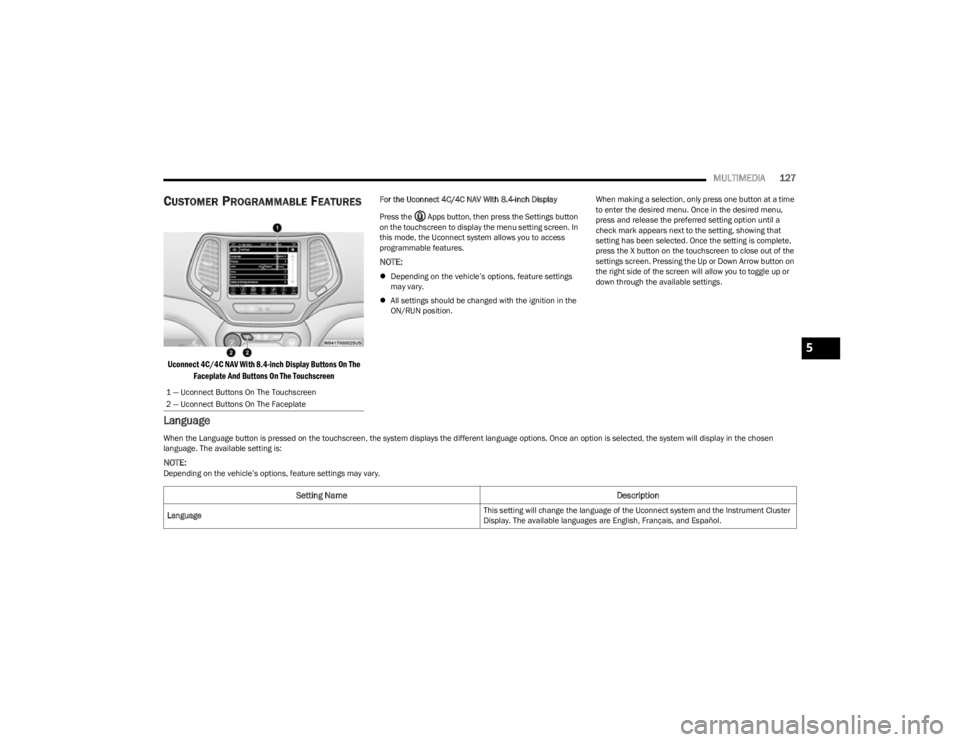
Uconnect 4C/4C NAV With 8.4-inch Display Buttons On The
Faceplate And Buttons On The Touchscreen
For the Uconnect 4C/4C NAV With 8.4-inch Display
Press the Apps button, then press the Settings button
on the touchscreen to display the menu setting screen. In
this mode, the Uconnect system allows you to access
programmable features.
NOTE:
Depending on the vehicle’s options, feature settings
may vary.
All settings should be changed with the ignition in the
ON/RUN position. When making a selection, only press one button at a time
to enter the desired menu. Once in the desired menu,
press and release the preferred setting option until a
check mark appears next to the setting, showing that
setting has been selected. Once the setting is complete,
press the X button on the touchscreen to close out of the
settings screen. Pressing the Up or Down Arrow button on
the right side of the screen will allow you to toggle up or
down through the available settings.
Language
1 — Uconnect Buttons On The Touchscreen
2 — Uconnect Buttons On The Faceplate
When the Language button is pressed on the touchscreen, the system displays the different language options. Once an option is selected, the system will display in the chosen
language. The available setting is:
NOTE:Depending on the vehicle’s options, feature settings may vary.
Setting Name
Description
Language This setting will change the language of the Uconnect system and the Instrument Cluster
Display. The available languages are English, Français, and Español.
5
23_KL_OM_EN_USC_t.book Page 127
Page 191 of 276
189
IN CASE OF EMERGENCY
HAZARD WARNING FLASHERS
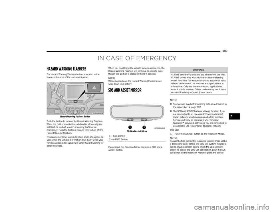
The Hazard Warning Flashers button is located in the
lower center area of the instrument panel.
Hazard Warning Flashers Button
Push the button to turn on the Hazard Warning Flashers.
When the button is activated, all directional turn signals
will flash on and off to warn oncoming traffic of an
emergency. Push the button a second time to turn off the
Hazard Warning Flashers.
This is an emergency warning system and it should not be
used when the vehicle is in motion. Use it only when your
vehicle is disabled or signaling a safety hazard warning for
other motorists.When you must leave the vehicle to seek assistance, the
Hazard Warning Flashers will continue to operate even
though the ignition is placed in the OFF position.
NOTE:With extended use, the Hazard Warning Flashers may
wear down your battery.
SOS AND ASSIST MIRROR
SOS And Assist Mirror
If equipped, the Rearview Mirror contains a SOS and a
ASSIST button.
NOTE:
Your vehicle may be transmitting data as authorized by
the subscriber Úpage 262.
The SOS and ASSIST buttons will only function if you
are connected to an operable LTE (voice/data) 4G
(data) network, which comes as a built in function.
Services will only be operable if your SiriusXM
Guardian™ service is active and you are connected to
an operable LTE (voice/data) 4G (data) network.
SOS Call
1. Push the SOS Call button on the Rearview Mirror.
NOTE:In case the SOS Call button is pushed in error, there will be
a 10 second delay before the SOS Call system initiates a
call to a SOS operator, during which the LED will blink
green. To cancel the SOS Call connection, push the SOS
call button on the Rearview Mirror or press the cancel -
1 — SOS Button
2 — ASSIST Button
WARNING!
ALWAYS obey traffic laws and pay attention to the road.
ALWAYS drive safely with your hands on the steering
wheel. You have full responsibility and assume all risks
related to the use of the features and applications in
this vehicle. Only use the features and applications
when it is safe to do so. Failure to do so may result in an
accident involving serious injury or death.
7
23_KL_OM_EN_USC_t.book Page 189
Page 192 of 276

190IN CASE OF EMERGENCY
(Continued)
lation button on the Device Screen. Termination of the
SOS Call will turn off the green LED light on the Rearview
Mirror.
2. The LED light located between the SOS and ASSIST
buttons on the Rearview Mirror will turn green once a
connection to a SOS operator has been made.
3. Once a connection between the vehicle and a SOS operator is made, the SOS Call system may transmit
the following important vehicle information to a SOS
operator:
Indication that the occupant placed a SOS Call.
The vehicle brand.
The last known GPS coordinates of the vehicle.
4. You should be able to speak with the SOS operator through the vehicle audio system to determine if
additional help is needed.
NOTE:
Your vehicle may be transmitting data as autho -
rized by the subscriber.
Once a connection is made between the vehicle’s
SOS Call system and the SOS operator, the SOS
operator may be able to open a voice connection
with the vehicle to determine if additional help is
needed. Once the SOS operator opens a voice
connection with the vehicle’s SOS Call system, the
operator should be able to speak with you or other
vehicle occupants and hear sounds occurring in
the vehicle. The vehicle’s SOS Call system will
attempt to remain connected with the SOS oper -
ator until the SOS operator terminates the connec -
tion.
5. The SOS operator may attempt to contact appropriate emergency responders and provide them with
important vehicle information and GPS coordinates.
SOS Call System Limitations
Vehicles sold in Mexico DO NOT have SOS Call system
capabilities.
SOS or other emergency line operators in Mexico may not
answer or respond to SOS system calls.
If the SOS Call system detects a malfunction, any of the
following may occur at the time the malfunction is
detected, and at the beginning of each ignition cycle:
The Rearview Mirror light located between the SOS and
ASSIST buttons will continuously illuminate red.
WARNING!
ALWAYS obey traffic laws and pay attention to the road.
ALWAYS drive safely with your hands on the steering
wheel. You have full responsibility and assume all risks
related to the use of the features and applications in
this vehicle. Only use the features and applications
when it is safe to do so. Failure to do so may result in an
accident involving serious injury or death.WARNING!
If anyone in the vehicle could be in danger (e.g., fire
or smoke is visible, dangerous road conditions or
location), do not wait for voice contact from an Emer -
gency Services Agent. All occupants should exit the
vehicle immediately and move to a safe location.
Never place anything on or near the vehicle’s oper -
able network and GPS antennas. You could prevent
operable network and GPS signal reception, which
can prevent your vehicle from placing an emergency
call. An operable network and GPS signal reception is
required for the SOS Call system to function properly.
The SOS Call system is embedded into the vehicle’s
electrical system. Do not add aftermarket electrical
equipment to the vehicle’s electrical system. This
may prevent your vehicle from sending a signal to
initiate an emergency call. To avoid interference that
can cause the SOS Call system to fail, never add
aftermarket equipment (e.g., two-way mobile radio,
CB radio, data recorder, etc.) to your vehicle’s elec -
trical system or modify the antennas on your vehicle.
IF YOUR VEHICLE LOSES BATTERY POWER FOR ANY
REASON (INCLUDING DURING OR AFTER AN ACCI -
DENT), THE UCONNECT FEATURES, APPS AND
SERVICES, AMONG OTHERS, WILL NOT OPERATE.
Modifications to any part of the SOS Call system
could cause the air bag system to fail when you need
it. You could be injured if the air bag system is not
there to help protect you.
WARNING!
23_KL_OM_EN_USC_t.book Page 190