ABS JEEP CHEROKEE 2023 Owners Manual
[x] Cancel search | Manufacturer: JEEP, Model Year: 2023, Model line: CHEROKEE, Model: JEEP CHEROKEE 2023Pages: 276, PDF Size: 12.55 MB
Page 6 of 276

4
CRUISE CONTROL SYSTEMS — IF EQUIPPED .................90
Cruise Control.............................................................. 90
Adaptive Cruise Control (ACC) ................................... 92
PARKSENSE FRONT/REAR PARK ASSIST
SYSTEM — IF EQUIPPED.....................................................99 ParkSense Sensors ................................................... 100
ParkSense Display .................................................... 100
ParkSense Warning Display ..................................... 103
Enabling And Disabling ParkSense.......................... 103Service The ParkSense Park Assist System ............ 103Cleaning The ParkSense System ............................. 103
ParkSense System Usage Precautions ................... 103Side Distance Warning System ................................ 104
PARKSENSE ACTIVE PARK ASSIST
SYSTEM — IF EQUIPPED.................................................. 106 Enabling And Disabling The ParkSense Active
Park Assist System.................................................... 106
Parallel/Perpendicular Parking Space Assistance
Operation ................................................................... 107
Exiting The Parking Space ........................................ 109
LANESENSE — IF EQUIPPED .......................................... 109 LaneSense Operation ............................................... 109Turning LaneSense On Or Off................................... 110
LaneSense Warning Message.................................. 110Changing LaneSense Settings ................................. 112
PARKVIEW REAR BACK UP CAMERA ........................... 112
REFUELING THE VEHICLE .............................................. 113
VEHICLE LOADING ........................................................... 113 Certification Label ..................................................... 113 TRAILER TOWING ............................................................ 114
Common Towing Definitions .................................... 114Trailer Hitch Classification ....................................... 116
Trailer Towing Weights (Maximum Trailer Weight
Ratings) ..................................................................... 116
Trailer And Tongue Weight ...................................... 117
Towing Requirements............................................... 117
Towing Tips ............................................................... 119
RECREATIONAL TOWING (BEHIND MOTORHOME) .... 120 Towing This Vehicle Behind Another Vehicle .......... 120
Recreational Towing — Front-Wheel Drive (FWD)
Models ....................................................................... 121Recreational Towing — 4x4 Models With 1-Speed
Power Transfer Unit .................................................. 121Recreational Towing — 4x4 Models With 2-Speed
Power Transfer Unit .................................................. 121
DRIVING TIPS ................................................................... 123 On-Road Driving Tips ................................................ 123
Off-Road Driving Tips ................................................ 123
MULTIMEDIA
UCONNECT SYSTEMS ..................................................... 126
CYBERSECURITY ............................................................. 126
UCONNECT SETTINGS ..................................................... 126 Customer Programmable Features ......................... 127
STEERING WHEEL AUDIO CONTROLS —
IF EQUIPPED ..................................................................... 140 Radio Operation ........................................................ 140Media Mode .............................................................. 140
RADIO OPERATION AND MOBILE PHONES.................. 140 Regulatory And Safety Information.......................... 140 OFF-ROAD PAGES — IF EQUIPPED .................................141
Off-Road Pages Status Bar ...................................... 141Drivetrain .................................................................. 141
Pitch & Roll ............................................................... 142
Accessory Gauges .................................................... 142
Selec-Terrain — If Equipped ..................................... 142
SAFETY
SAFETY FEATURES ...........................................................143 Anti-Lock Brake System (ABS) ................................. 143
Electronic Brake Control (EBC) System ................... 143
AUXILIARY DRIVING SYSTEMS .......................................150 Blind Spot Monitoring (BSM) — If Equipped ............ 150
Forward Collision Warning (FCW) With
Mitigation — If Equipped ........................................... 154
Tire Pressure Monitoring System (TPMS) ................ 155
OCCUPANT RESTRAINT SYSTEMS ................................159 Occupant Restraint Systems Features ................... 159
Important Safety Precautions................................... 159
Seat Belt Systems .................................................... 159
Supplemental Restraint Systems (SRS) .................. 166Child Restraints ......................................................... 176
SAFETY TIPS......................................................................186 Transporting Passengers .......................................... 186
Transporting Pets ...................................................... 186Connected Vehicles................................................... 186
Safety Checks You Should Make Inside The
Vehicle ....................................................................... 187
Periodic Safety Checks You Should Make
Outside The Vehicle .................................................. 188
Exhaust Gas ............................................................... 188
Carbon Monoxide Warnings ..................................... 188
23_KL_OM_EN_USC_t.book Page 4
Page 12 of 276
10
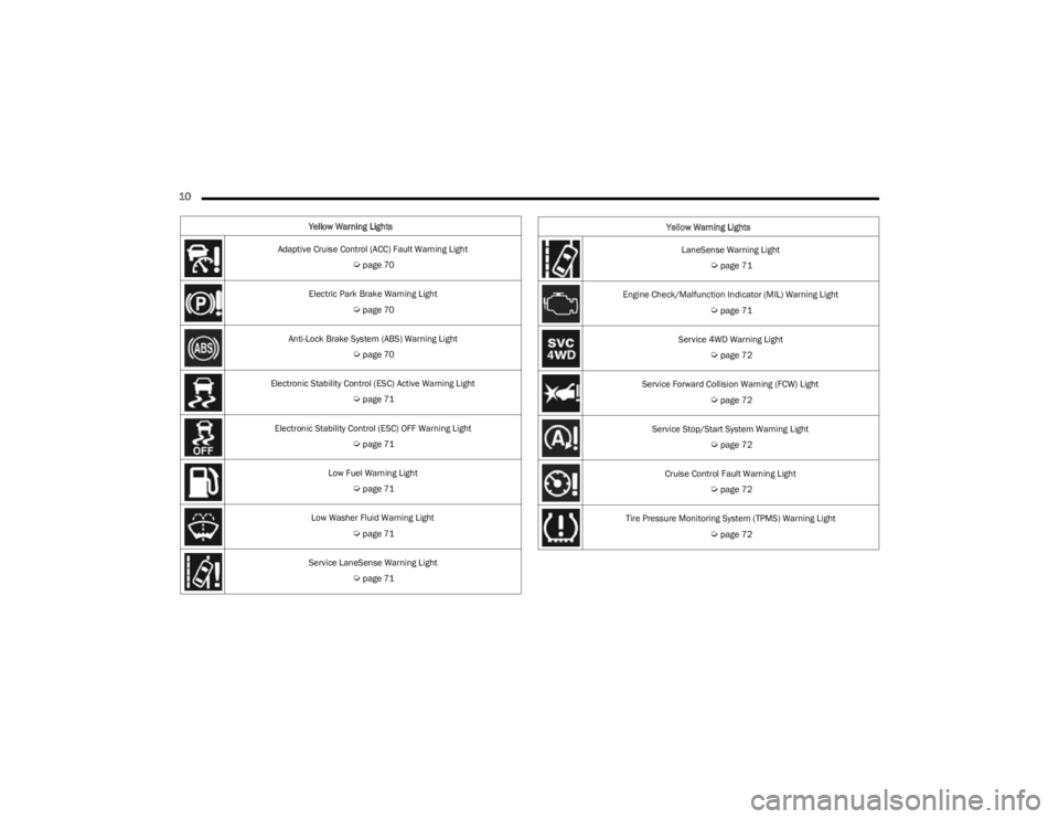
Yellow Warning Lights
Adaptive Cruise Control (ACC) Fault Warning Light
Úpage 70
Electric Park Brake Warning Light
Úpage 70
Anti-Lock Brake System (ABS) Warning Light
Úpage 70
Electronic Stability Control (ESC) Active Warning Light
Úpage 71
Electronic Stability Control (ESC) OFF Warning Light
Úpage 71
Low Fuel Warning Light
Úpage 71
Low Washer Fluid Warning Light
Úpage 71
Service LaneSense Warning Light
Úpage 71
LaneSense Warning Light
Úpage 71
Engine Check/Malfunction Indicator (MIL) Warning Light
Úpage 71
Service 4WD Warning Light
Úpage 72
Service Forward Collision Warning (FCW) Light
Úpage 72
Service Stop/Start System Warning Light
Úpage 72
Cruise Control Fault Warning Light
Úpage 72
Tire Pressure Monitoring System (TPMS) Warning Light
Úpage 72
Yellow Warning Lights
23_KL_OM_EN_USC_t.book Page 10
Page 70 of 276
68GETTING TO KNOW YOUR INSTRUMENT PANEL
After a trip:
Check if any aftermarket equipment was installed
(additional lights, upfitter electrical accessories, audio
systems, alarms) and review specifications if any (load
and Ignition Off Draw currents).
Evaluate the latest driving cycles (distance, driving
time and parking time).
The vehicle should have service performed if the
message is still present during consecutive trips and
the evaluation of the vehicle and driving pattern did not
help to identify the cause.
WARNING LIGHTS AND MESSAGES
The warning/indicator lights will illuminate in the
instrument panel together with a dedicated message and/
or acoustic signal when applicable. These indications are
indicative and precautionary and as such must not be
considered as exhaustive. Always refer to the information
in this chapter in the event of a failure indication. All active
telltales will display first if applicable. The system check
menu may appear different based upon equipment
options and current vehicle status. Some telltales are
optional and may not appear.
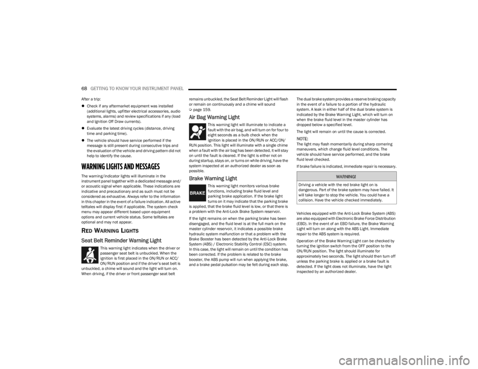
RED WARNING LIGHTS
Seat Belt Reminder Warning Light
This warning light indicates when the driver or
passenger seat belt is unbuckled. When the
ignition is first placed in the ON/RUN or ACC/
ON/RUN position and if the driver’s seat belt is
unbuckled, a chime will sound and the light will turn on.
When driving, if the driver or front passenger seat belt remains unbuckled, the Seat Belt Reminder Light will flash
or remain on continuously and a chime will sound
Úpage 159.
Air Bag Warning Light
This warning light will illuminate to indicate a
fault with the air bag, and will turn on for four to
eight seconds as a bulb check when the
ignition is placed in the ON/RUN or ACC/ON/
RUN position. This light will illuminate with a single chime
when a fault with the air bag has been detected, it will stay
on until the fault is cleared. If the light is either not on
during startup, stays on, or turns on while driving, have the
system inspected at an authorized dealer as soon as
possible.
Brake Warning Light
This warning light monitors various brake
functions, including brake fluid level and
parking brake application. If the brake light
turns on it may indicate that the parking brake
is applied, that the brake fluid level is low, or that there is
a problem with the Anti-Lock Brake System reservoir.
If the light remains on when the parking brake has been
disengaged, and the fluid level is at the full mark on the
master cylinder reservoir, it indicates a possible brake
hydraulic system malfunction or that a problem with the
Brake Booster has been detected by the Anti-Lock Brake
System (ABS) / Electronic Stability Control (ESC) system.
In this case, the light will remain on until the condition has
been corrected. If the problem is related to the brake
booster, the ABS pump will run when applying the brake,
and a brake pedal pulsation may be felt during each stop. The dual brake system provides a reserve braking capacity
in the event of a failure to a portion of the hydraulic
system. A leak in either half of the dual brake system is
indicated by the Brake Warning Light, which will turn on
when the brake fluid level in the master cylinder has
dropped below a specified level.
The light will remain on until the cause is corrected.
NOTE:The light may flash momentarily during sharp cornering
maneuvers, which change fluid level conditions. The
vehicle should have service performed, and the brake
fluid level checked.
If brake failure is indicated, immediate repair is necessary.
Vehicles equipped with the Anti-Lock Brake System (ABS)
are also equipped with Electronic Brake Force Distribution
(EBD). In the event of an EBD failure, the Brake Warning
Light will turn on along with the ABS Light. Immediate
repair to the ABS system is required.
Operation of the Brake Warning Light can be checked by
turning the ignition switch from the OFF position to the
ON/RUN position. The light should illuminate for
approximately two seconds. The light should then turn off
unless the parking brake is applied or a brake fault is
detected. If the light does not illuminate, have the light
inspected by an authorized dealer.
WARNING!
Driving a vehicle with the red brake light on is
dangerous. Part of the brake system may have failed. It
will take longer to stop the vehicle. You could have a
collision. Have the vehicle checked immediately.
23_KL_OM_EN_USC_t.book Page 68
Page 72 of 276
70GETTING TO KNOW YOUR INSTRUMENT PANEL
light turns on while driving, pull the vehicle to the side of
the road at a safe location, stop the vehicle, shut off the
engine as soon as possible, check the oil level and correct
the oil level if it is low. Contact an authorized dealer.
Do not operate the vehicle until the cause is corrected.
This light may or may not indicate how much oil is in the
engine. If the oil level is low and corrected, the engine can
be restarted. Otherwise the vehicle should be serviced by
an authorized dealer
Úpage 208.
NOTE:The light may flash, a message in the center of the dash
may display momentarily “low oil pressure” and a chime
may occur during sharp cornering maneuvers. If this
happen it may indicate a low oil level. The oil level should
be checked and dealer service performed if this occurs.
Oil Temperature Warning Light
This warning light will illuminate to indicate the
engine oil temperature is high. If the light turns
on while driving, stop the vehicle and shut off
the engine as soon as possible. Wait for oil
temperature to return to normal levels.
Transmission Temperature Warning Light
This warning light will illuminate to warn of a
high transmission fluid temperature. This may
occur with strenuous usage such as trailer
towing. If this light turns on, stop the vehicle
and run the engine at idle or slightly faster, with the
transmission in PARK (P) or NEUTRAL (N), until the light
turns off. Once the light turns off, you may continue to
drive normally.
Vehicle Security Warning Light —
If Equipped
This light will flash at a fast rate for
approximately 15 seconds when the Vehicle
Security System is arming, and then will flash
slowly until the vehicle is disarmed.
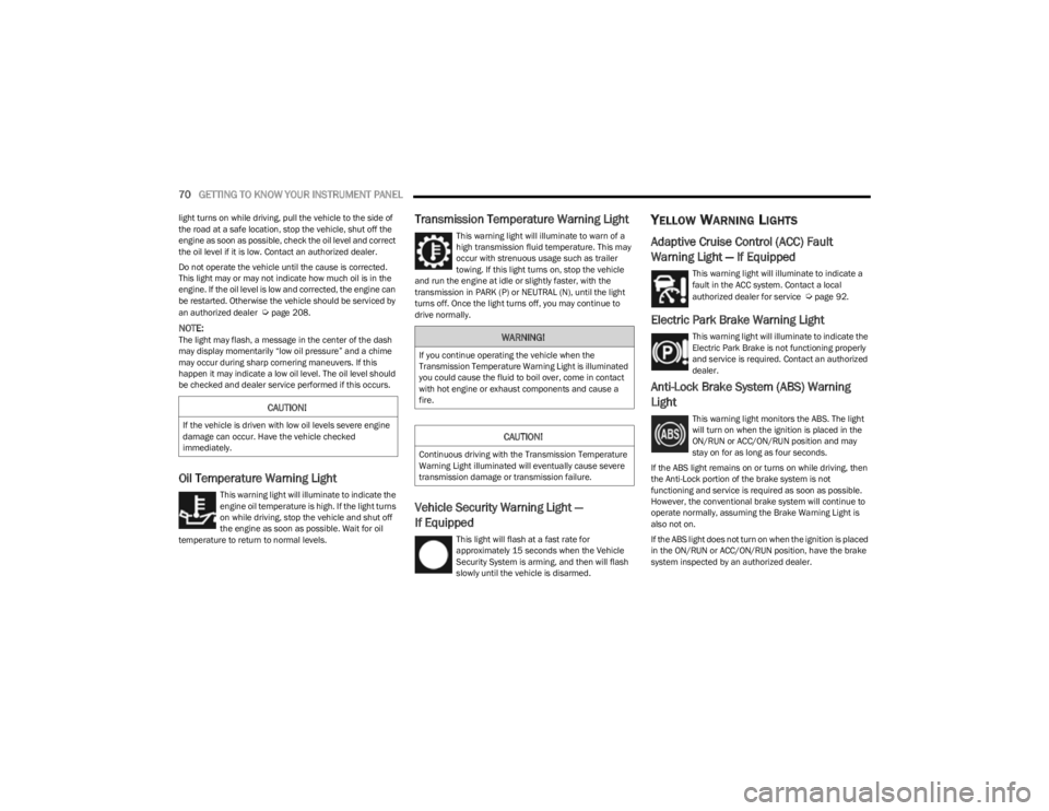
YELLOW WARNING LIGHTS
Adaptive Cruise Control (ACC) Fault
Warning Light — If Equipped
This warning light will illuminate to indicate a
fault in the ACC system. Contact a local
authorized dealer for service
Úpage 92.
Electric Park Brake Warning Light
This warning light will illuminate to indicate the
Electric Park Brake is not functioning properly
and service is required. Contact an authorized
dealer.
Anti-Lock Brake System (ABS) Warning
Light
This warning light monitors the ABS. The light
will turn on when the ignition is placed in the
ON/RUN or ACC/ON/RUN position and may
stay on for as long as four seconds.
If the ABS light remains on or turns on while driving, then
the Anti-Lock portion of the brake system is not
functioning and service is required as soon as possible.
However, the conventional brake system will continue to
operate normally, assuming the Brake Warning Light is
also not on.
If the ABS light does not turn on when the ignition is placed
in the ON/RUN or ACC/ON/RUN position, have the brake
system inspected by an authorized dealer.CAUTION!
If the vehicle is driven with low oil levels severe engine
damage can occur. Have the vehicle checked
immediately.
WARNING!
If you continue operating the vehicle when the
Transmission Temperature Warning Light is illuminated
you could cause the fluid to boil over, come in contact
with hot engine or exhaust components and cause a
fire.
CAUTION!
Continuous driving with the Transmission Temperature
Warning Light illuminated will eventually cause severe
transmission damage or transmission failure.
23_KL_OM_EN_USC_t.book Page 70
Page 96 of 276
94STARTING AND OPERATING
To Activate/Deactivate
Push and release the Adaptive Cruise Control (ACC) on/off
button. The ACC menu in the instrument cluster display
will read “ACC Ready.”
To turn the system off, push and release the Adaptive
Cruise Control (ACC) on/off button again. At this time, the
system will turn off and the instrument cluster display will
read “Adaptive Cruise Control (ACC) Off.”
To Set A Desired Speed
When the vehicle reaches the speed desired, push the
SET (+) button or the SET (-) button and release. The
instrument cluster display will show the set speed.
NOTE:Fixed Speed Cruise Control can be used without ACC
enabled. To change between the different modes, push
the ACC on/off button which turns the ACC and the Fixed
Speed Cruise Control off. Pushing the Fixed Speed Cruise
Control on/off button will result in turning on (changing to)
Fixed Speed Cruise Control mode.
If ACC is set when the vehicle speed is
below
20 mph
(32 km/h), the set speed will default to 20 mph (32 km/h).
NOTE:Fixed Speed Cruise Control cannot be set below 20 mph
(32 km/h).
If either system is set when the vehicle speed is above
20 mph (32 km/h), the set speed shall be the current speed of the vehicle.
NOTE:
Keeping your foot on the accelerator pedal can cause
the vehicle to continue to accelerate beyond the set
speed. If this occurs, the message “DRIVER OVERRIDE”
will display in the instrument cluster display.
If you continue to accelerate beyond the set speed
while ACC is enabled, the system will not be controlling
the distance between your vehicle and the vehicle
ahead. The vehicle speed will only be determined by
the position of the accelerator pedal.
To Cancel
The following conditions cancel the ACC or Fixed Speed
Cruise Control systems:
The brake pedal is applied
The CANC (cancel) button is pushed
The Anti-Lock Brake System (ABS) activates
The gear selector is removed from the DRIVE position
The Electronic Stability Control/Traction Control
System (ESC/TCS) activates
The vehicle parking brake is applied
The Trailer Sway Control (TSC) activates
The driver switches ESC to Full Off mode
The braking temperature exceeds normal range (over -
heated)
The following conditions will only cancel the ACC system:
Driver seat belt is unbuckled at low speeds
Driver door is opened at low speeds
To Turn Off
The system will turn off and erase the set speed in
memory if:
The Adaptive Cruise Control (ACC) on/off button is
pushed
The Fixed Speed Cruise Control on/off button is pushed
The ignition is placed in the OFF position
4WD Low is engaged
WARNING!
Leaving the Adaptive Cruise Control (ACC) system on
when not in use is dangerous. You could accidentally
set the system or cause it to go faster than you want.
You could lose control and have a collision. Always leave
the system off when you are not using it.
WARNING!
In Fixed Speed Cruise Control mode, the system will not
react to vehicles ahead. In addition, the proximity
warning does not activate and no alarm will sound even
if you are too close to the vehicle ahead since neither
the presence of the vehicle ahead nor the
vehicle-to-vehicle distance is detected. Be sure to
maintain a safe distance between your vehicle and the
vehicle ahead. Always be aware which mode is
selected.
23_KL_OM_EN_USC_t.book Page 94
Page 108 of 276
106STARTING AND OPERATING
PARKSENSE ACTIVE PARK ASSIST
SYSTEM — IF EQUIPPED
The ParkSense Active Park Assist system is intended to
assist the driver during parallel, perpendicular, and
parallel park exit maneuvers by identifying a proper
parking space, providing audible/visual instructions, and
controlling the steering wheel. The ParkSense Active Park
Assist system is defined as “semi-automatic” since the
driver maintains control of the accelerator, gear selector
and brakes. Depending on the driver's parking maneuver
selection, the ParkSense Active Park Assist system is
capable of maneuvering a vehicle into a parallel or a
perpendicular parking space on either side (i.e., driver
side or passenger side), as well as exiting a parallel
parking space.
NOTE:
The driver is always responsible for controlling the
vehicle, responsible for any surrounding objects, and
must intervene as required during a parking maneuver.
The system is designed to assist the driver and not to
substitute the driver.
During a semi-automatic maneuver, if the driver
touches the steering wheel after being instructed to
remove their hands from the steering wheel, the
system will cancel, and the driver will be required to
manually complete the parking maneuver.
The system may not work in all conditions (e.g. environ -
mental conditions such as heavy rain, snow, etc., or if
searching for a parking space that has surfaces that
will absorb the ultrasonic sensor waves).
New vehicles from the dealer must have at least
30 miles (48 km) accumulated before the ParkSense
Active Park Assist system is fully calibrated and
performs accurately. This is due to the system’s
dynamic vehicle calibration to improve the perfor -
mance of the feature. The system will also continuously
perform the dynamic vehicle calibration to account for
differences such as over or under inflated tires and
new tires.
ENABLING AND DISABLING THE
P
ARKSENSE ACTIVE PARK ASSIST
S
YSTEM
The ParkSense Active Park Assist system can
be enabled and disabled with the ParkSense
Active Park Assist switch, located on the switch
panel below the Uconnect display.
To enable or disable the ParkSense Active Park Assist
system, push the ParkSense Active Park Assist switch
once (LED turns on). Pushing the switch a second time will
disable the system (LED turns off). The ParkSense Active Park Assist system will turn off
automatically for any of the following conditions:
Parking maneuver is completed
Vehicle speed is greater than 18 mph (30 km/h) when
searching for a parking space
Vehicle speed is greater than 5 mph (7 km/h) during
active steering guidance into the parking space
Steering wheel is touched during active steering guid -
ance into the parking space
ParkSense switch is pushed
Driver's door is opened
Rear liftgate is opened
Electronic Stability Control/Anti-Lock Braking System
intervention
NOTE:The ParkSense Active Park Assist system allows a
maximum number of shifts between DRIVE and REVERSE.
If the maneuver cannot be completed within the maximum
amount of shifts, the system will cancel and the
instrument cluster display will instruct the driver to
complete the maneuver manually.
The ParkSense Active Park Assist system will only operate
and search for a parking space when the following
conditions are present:
Gear selector is in DRIVE.
Ignition is in the RUN position.
ParkSense Active Park Assist switch is activated.
Driver's door is closed.
Rear liftgate is closed.
The vehicle must be driven slowly when using Park -
Sense in order to be able to stop in time when an
obstacle is detected. It is recommended that the
driver looks over his/her shoulder when using Park -
Sense.
CAUTION!
23_KL_OM_EN_USC_t.book Page 106
Page 145 of 276
143
SAFETY
SAFETY FEATURES
ANTI-LOCK BRAKE SYSTEM (ABS)
The ABS provides increased vehicle stability and brake
performance under most braking conditions. The system
automatically prevents wheel lock and enhances vehicle
control during braking.
The ABS performs a self-check cycle to ensure that the
ABS is working properly each time the vehicle is started
and driven. During this self-check, you may hear a slight
clicking sound as well as some related motor noises.
The ABS is activated during braking when the system
detects one or more wheels are beginning to lock. Road
conditions such as ice, snow, gravel, bumps, railroad
tracks, loose debris, or panic stops may increase the
likelihood of ABS activation(s).
You also may experience the following normal
characteristics when the ABS activates:
ABS motor noise or clicking sounds (you may continue
to hear for a short time after the stop).
Brake pedal pulsations.
A slight drop of the brake pedal at the end of the stop.
The ABS is designed to function with the Original
Equipment Manufacturer (OEM) tires. Modification may
result in degraded ABS performance.
Anti-Lock Brake System (ABS) Warning
Light
The yellow ABS Warning Light will turn on when the ignition
is placed in the ON/RUN mode and may stay on for as long
as four seconds.
If the ABS Warning Light remains on or comes on while
driving, it indicates that the anti-lock portion of the brake
system is not functioning and that service is required.
However, the conventional brake system will continue to
operate normally if the ABS Warning Light is on.
If the ABS Warning Light is on, the brake system should be
serviced as soon as possible to restore the benefits of
Anti-Lock Brakes. If the ABS Warning Light does not come
on when the ignition is placed in the ON/RUN mode, have
the light repaired as soon as possible.
ELECTRONIC BRAKE CONTROL (EBC)
S
YSTEM
Your vehicle is equipped with an advanced EBC system.
This system includes Anti-Lock Brake System (ABS), Brake
Assist System (BAS), Electronic Brake Force Distribution
(EBD), Electronic Roll Mitigation (ERM), Electronic Stability
Control (ESC), Hill Start Assist (HSA), and Traction Control
System (TCS). These systems work together to enhance
both vehicle stability and control in various driving
conditions.
WARNING!
The ABS contains sophisticated electronic equip -
ment that may be susceptible to interference caused
by improperly installed or high output radio transmit -
ting equipment. This interference can cause possible
loss of anti-lock braking capability. Installation of
such equipment should be performed by qualified
professionals.
Pumping of the Anti-Lock Brakes will diminish their
effectiveness and may lead to a collision. Pumping
makes the stopping distance longer. Just press firmly
on your brake pedal when you need to slow down or
stop.
The ABS cannot prevent the natural laws of physics
from acting on the vehicle, nor can it increase
braking or steering efficiency beyond that afforded
by the condition of the vehicle brakes and tires or the
traction afforded.
The ABS cannot prevent collisions, including those
resulting from excessive speed in turns, following
another vehicle too closely, or hydroplaning.
The capabilities of an ABS equipped vehicle must
never be exploited in a reckless or dangerous
manner that could jeopardize the user’s safety or the
safety of others.
6
23_KL_OM_EN_USC_t.book Page 143
Page 146 of 276
144SAFETY
Your vehicle may also be equipped with Dynamic Steering
Torque (DST), Hill Descent Control (HDC), Rain Brake
Support (RBS), Ready Alert Braking (RAB), Selec-Speed
Control (SSC), and Trailer Sway Control (TSC).
Brake Assist System (BAS)
The BAS is designed to optimize the vehicle’s braking
capability during emergency braking maneuvers. The
system detects an emergency braking situation by sensing
the rate and amount of brake application and then applies
optimum pressure to the brakes. This can help reduce
braking distances. The BAS complements the Anti-Lock
Brake System (ABS). Applying the brakes very quickly
results in the best BAS assistance. To receive the benefit
of the system, you must apply continuous braking
pressure during the stopping sequence (do not “pump”
the brakes). Do not reduce brake pedal pressure unless
braking is no longer desired. Once the brake pedal is
released, the BAS is deactivated.
Brake System Warning Light
The red Brake System Warning Light will turn on when the
ignition is placed in the ON/RUN mode and may stay on for
as long as four seconds.
If the Brake System Warning Light remains on or comes on
while driving, it indicates that the brake system is not
functioning properly and that immediate service is
required. If the Brake System Warning Light does not
come on when the ignition is placed in the ON/RUN mode,
have the light repaired as soon as possible.
Dynamic Steering Torque (DST)
DST is a feature of the Electronic Stability Control (ESC)
and the Electric Power Steering (EPS) modules, that
provides torque at the steering wheel for certain driving
conditions, in which the ESC module is detecting vehicle
instability. The torque that the steering wheel receives is
only meant to help the driver realize optimal steering
behavior in order to reach/maintain vehicle stability. The
only notification the driver receives that the feature is
active is the torque applied to the steering wheel.
NOTE:The DST feature is only meant to help the driver realize the
correct course of action through small torques on the
steering wheel, which means the effectiveness of the DST
feature is highly dependent on the driver’s sensitivity and
overall reaction to the applied torque. It is very important
to realize that this feature will not steer the vehicle,
meaning the driver is still responsible for steering the
vehicle.
Electronic Brake Force Distribution (EBD)
EBD function manages the distribution of the braking
torque between the front and rear axles by limiting braking
pressure to the rear axle. This is done to prevent overslip of
the rear wheels to avoid vehicle instability, and to prevent
the rear axle from entering ABS before the front axle.
Electronic Roll Mitigation (ERM)
ERM anticipates the potential for wheel lift by monitoring
the driver’s steering wheel input and the speed of the
vehicle. When ERM determines that the rate of change of
the steering wheel angle and vehicle’s speed are
sufficient to potentially cause wheel lift, it then applies the
appropriate brake and may also reduce engine power to
lessen the chance that wheel lift will occur. ERM can only
reduce the chance of wheel lift occurring during severe or
evasive driving maneuvers; it cannot prevent wheel lift
due to other factors, such as road conditions, leaving the
roadway, or striking objects or other vehicles.
NOTE:ERM is disabled any time the ESC is in “Full Off” mode (if
equipped) Úpage 145.
WARNING!
The Brake Assist System (BAS) cannot prevent the natu -
ral laws of physics from acting on the vehicle, nor can it
increase the traction afforded by prevailing road condi -
tions. BAS cannot prevent collisions, including those
resulting from excessive speed in turns, driving on very
slippery surfaces, or hydroplaning. The capabilities of a
BAS-equipped vehicle must never be exploited in a
reckless or dangerous manner, which could jeopardize
the user's safety or the safety of others.
WARNING!
Many factors, such as vehicle loading, road conditions
and driving conditions, influence the chance that wheel
lift or rollover may occur. ERM cannot prevent all wheel
lift or rollovers, especially those that involve leaving the
roadway or striking objects or other vehicles. The capa -
bilities of an ERM-equipped vehicle must never be
exploited in a reckless or dangerous manner which could
jeopardize the user's safety or the safety of others.
23_KL_OM_EN_USC_t.book Page 144
Page 174 of 276
172SAFETY
Do not replace the seat cover or cushion with an after -
market seat cover or cushion.
Do not add a secondary seat cover or mat.
At no time should any Supplemental Restraint System
(SRS) component or SRS related component or
fastener be modified or replaced with any part except
those which are approved by FCA US LLC.
Knee Impact Bolsters
The Knee Impact Bolsters help protect the knees of the
driver and front passenger, and position the front
occupants for improved interaction with the front air bags.
Supplemental Driver And Front Passenger
Knee Air Bags
This vehicle is equipped with a Supplemental Driver Knee
Air Bag mounted in the instrument panel below the
steering column and a Supplemental Passenger Knee Air
Bag mounted in the instrument panel below the glove
compartment. The Supplemental Knee Air Bags provide
enhanced protection during a frontal impact by working
together with the seat belts, pretensioners, and front air
bags.
Supplemental Side Air Bags
Supplemental Seat-Mounted Side Air Bags (SABs)
This vehicle is equipped with Supplemental Seat-Mounted
Side Air Bags (SABs).
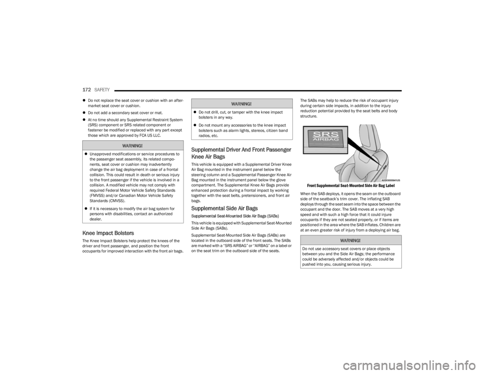
Supplemental Seat-Mounted Side Air Bags (SABs) are
located in the outboard side of the front seats. The SABs
are marked with a “SRS AIRBAG” or “AIRBAG” on a label or
on the seat trim on the outboard side of the seats. The SABs may help to reduce the risk of occupant injury
during certain side impacts, in addition to the injury
reduction potential provided by the seat belts and body
structure.
Front Supplemental Seat-Mounted Side Air Bag Label
When the SAB deploys, it opens the seam on the outboard
side of the seatback’s trim cover. The inflating SAB
deploys through the seat seam into the space between the
occupant and the door. The SAB moves at a very high
speed and with such a high force that it could injure
occupants if they are not seated properly, or if items are
positioned in the area where the SAB inflates. Children are
at an even greater risk of injury from a deploying air bag.
WARNING!
Unapproved modifications or service procedures to
the passenger seat assembly, its related compo -
nents, seat cover or cushion may inadvertently
change the air bag deployment in case of a frontal
collision. This could result in death or serious injury
to the front passenger if the vehicle is involved in a
collision. A modified vehicle may not comply with
required Federal Motor Vehicle Safety Standards
(FMVSS) and/or Canadian Motor Vehicle Safety
Standards (CMVSS).
If it is necessary to modify the air bag system for
persons with disabilities, contact an authorized
dealer.
WARNING!
Do not drill, cut, or tamper with the knee impact
bolsters in any way.
Do not mount any accessories to the knee impact
bolsters such as alarm lights, stereos, citizen band
radios, etc.
WARNING!
Do not use accessory seat covers or place objects
between you and the Side Air Bags; the performance
could be adversely affected and/or objects could be
pushed into you, causing serious injury.
23_KL_OM_EN_USC_t.book Page 172
Page 200 of 276
198IN CASE OF EMERGENCY
SEALING A TIRE WITH TIRE SERVICE KIT
(A) Whenever You Stop To Use Tire Service
Kit:
1. Pull over to a safe location and turn on the vehicle’s
Hazard Warning Flashers.
2. Verify that the valve stem (on the wheel with the deflated tire) is in a position that is near to the
ground. This will allow the Tire Service Kit Hoses and to reach the valve stem and keep the Tire Service Kit
flat on the ground. This will provide the best
positioning of the kit when injecting the sealant into
the deflated tire and running the air pump. Move the
vehicle as necessary to place the valve stem in this
position before proceeding.
3. Place the transmission in PARK (P) (auto transmission) or in Gear (manual transmission) and
place the ignition in the OFF position.
4. Apply the parking brake.
(B) Setting Up To Use Tire Service Kit:
1. Push in the Mode Select Knob and turn to the Sealant Mode position.
2. Uncoil the Sealant Hose and then remove the cap from the fitting at the end of the hose.
3. Place the Tire Service Kit flat on the ground next to the deflated tire.
4. Remove the cap from the valve stem and then screw the fitting at the end of the Sealant Hose onto the
valve stem.
5. Uncoil the Power Plug and insert the plug into the vehicle’s 12 Volt power outlet.
NOTE:Do not remove foreign objects (e.g., screws or nails) from
the tire.
(C) Injecting Tire Service Kit Sealant Into
The Deflated Tire:
Always start the engine before turning ON the Tire
Service Kit.
NOTE:Manual transmission vehicles must have the parking
brake engaged and the gear selector in NEUTRAL.
After pushing the Power Button, the sealant (white
fluid) will flow from the Sealant Bottle through the
Sealant Hose and into the tire.
NOTE:Sealant may leak out through the puncture in the tire.
If the sealant (white fluid) does not flow within
0 – 10 seconds through the Sealant Hose:
1. Push the Power Button to turn Off the Tire Service
Kit. Disconnect the Sealant Hose from the valve
stem. Make sure the valve stem is free of debris.
Reconnect the Sealant Hose to the valve stem.
Check that the Mode Select Knob is in the Sealant
Mode position and not Air Mode. Push the Power
Button to turn On the Tire Service Kit.
2. Connect the Power Plug to a different 12 Volt power outlet in your vehicle or another vehicle, if available.
Make sure the engine is running before turning ON
the Tire Service Kit.
3. The Sealant Bottle may be empty due to previous use. Call for assistance.
NOTE:If the Mode Select Knob is on Air Mode and the pump is
operating, air will dispense from the Air Pump Hose only,
not the Sealant Hose.
A loose Tire Service Kit thrown forward in a collision
or hard stop could endanger the occupants of the
vehicle. Always stow the Tire Service Kit in the place
provided. Failure to follow these warnings can result
in injuries that are serious or fatal to you, your
passengers, and others around you.
Take care not to allow the contents of Tire Service Kit
to come in contact with hair, eyes, or clothing. Tire
Service Kit sealant is harmful if inhaled, swallowed,
or absorbed through the skin. It causes skin, eye, and
respiratory irritation. Flush immediately with plenty of
water if there is any contact with eyes or skin. Change
clothing as soon as possible, if there is any contact
with clothing.
Tire Service Kit Sealant solution contains latex. In
case of an allergic reaction or rash, consult a physi -
cian immediately. Keep Tire Service Kit out of reach
of children. If swallowed, rinse mouth immediately
with plenty of water and drink plenty of water. Do not
induce vomiting! Consult a physician immediately.
WARNING!
23_KL_OM_EN_USC_t.book Page 198