tow JEEP CHEROKEE 2023 Owners Manual
[x] Cancel search | Manufacturer: JEEP, Model Year: 2023, Model line: CHEROKEE, Model: JEEP CHEROKEE 2023Pages: 276, PDF Size: 12.55 MB
Page 2 of 276

WARNING: Operating, servicing and maintaining a passenger vehicle or off-highway
motor vehicle can expose you to chemicals including engine exhaust, carbon monoxide,
phthalates, and lead, which are known to the State of California to cause cancer and
birth defects or other reproductive harm. To minimize exposure, avoid breathing exhaust,
do not idle the engine except as necessary, service your vehicle in a well-ventilated area
and wear gloves or wash your hands frequently when servicing your vehicle. For more
information go to www.P65Warnings.ca.gov/passenger-vehicle.
This Owner’s Manual illustrates and describes the operation of features and equipment that are either standard or optional on this vehicle. This manual may also include a description of features and equipment that are no longer available or were not ordered on this vehicle. Please disregard any features and equipment described in this manual that are not on this vehicle. FCA US LLC reserves the right to make changes in design and specifications, and/or make additions to or improvements to its products without imposing any obligation upon itself to install them on products previously manufactured.
With respect to any vehicles sold in Canada, the name FCA US LLC shall be deemed to be deleted and the name FCA Canada Inc. used in substitution therefore.
This Owner’s Manual is intended to familiarize you with the important features of your vehicle. Your most up-to-date Owner’s Manual, Navigation/Uconnect manuals and Warranty Booklet can be found by visiting the website on the back cover.
ROADSIDE ASSISTANCE 24 HOURS, 7 DAYS A WEEK AT YOUR SERVICE. CALL 1-800-521-2779 OR VISIT CHRYSLER.RSAHELP.COM (USA) CALL 1-800-363-4869 OR VISIT FCA.ROADSIDEAID.COM (CANADA) SERVICES: Flat Tire Service, Out Of Gas/Fuel Delivery, Battery Jump Assistance, Lockout Service and Towing Service
Please see the Customer Assistance chapter in this Owner’s Manual for further information.
FCA US LLC reserves the right to modify the terms or discontinue the Roadside Assistance Program at any time. The Roadside Assistance Program is subject to restrictions and conditions of use, that are determined solely by FCA US LLC.
The driver’s primary responsibility is the safe operation of the vehicle. Driving while distracted can result in loss of vehicle control, resulting in an accident and personal injury. FCA US LLC strongly recommends that the driver use extreme caution when using any device or feature that may take their attention off the road. Use of any electrical devices, such as cellular telephones, computers, portable radios, vehicle navigation or other devices by the driver while the vehicle is moving is dangerous and could lead to a serious accident. Texting while driving is also dangerous and should never be done while the vehicle is moving. If you find yourself unable to devote your full attention to vehicle operation, pull off the road to a safe location and stop your vehicle. Some states or provinces prohibit the use of cellular telephones or texting while driving. It is always the driver’s responsibility to comply with all local laws.
This Owner’s Manual has been prepared to help you get acquainted with your new Jeep® brand vehicle and to provide a convenient reference source for common questions.
Not all features shown in this manual may apply to your vehicle. For additional information, visit mopar.com/om (USA), owners.mopar.ca (Canada) or your local Jeep® brand dealer.
U.S. Residents: If you are the first registered retail owner of your vehicle, you may obtain a complimentary printed copy of the Warranty Booklet by calling 1-877-426-5337 or by contacting your dealer. Replacement kits can be purchased by visiting www.techauthority.com.
Canadian Residents: If you are the first registered retail owner of your vehicle, you may obtain a complimentary printed copy of the Warranty Booklet or purchase a replacement kit by calling 1-800-387-1143 or by contacting your dealer.
DRIVING AND ALCOHOL
Drunk driving is one of the most frequent causes of accidents. Your driving ability can be seriously impaired with blood alcohol levels far below the legal minimum. If you are drinking, don’t drive. Ride with a designated non-drinking driver, call a cab, a rideshare, a friend or use public transportation.
WARNING
Driving after drinking can lead to an accident. Your perceptions are less sharp, your reflexes are slower and your judgment is impaired when you have been drinking. Never drink and then drive.
Page 6 of 276

4
CRUISE CONTROL SYSTEMS — IF EQUIPPED .................90
Cruise Control.............................................................. 90
Adaptive Cruise Control (ACC) ................................... 92
PARKSENSE FRONT/REAR PARK ASSIST
SYSTEM — IF EQUIPPED.....................................................99 ParkSense Sensors ................................................... 100
ParkSense Display .................................................... 100
ParkSense Warning Display ..................................... 103
Enabling And Disabling ParkSense.......................... 103Service The ParkSense Park Assist System ............ 103Cleaning The ParkSense System ............................. 103
ParkSense System Usage Precautions ................... 103Side Distance Warning System ................................ 104
PARKSENSE ACTIVE PARK ASSIST
SYSTEM — IF EQUIPPED.................................................. 106 Enabling And Disabling The ParkSense Active
Park Assist System.................................................... 106
Parallel/Perpendicular Parking Space Assistance
Operation ................................................................... 107
Exiting The Parking Space ........................................ 109
LANESENSE — IF EQUIPPED .......................................... 109 LaneSense Operation ............................................... 109Turning LaneSense On Or Off................................... 110
LaneSense Warning Message.................................. 110Changing LaneSense Settings ................................. 112
PARKVIEW REAR BACK UP CAMERA ........................... 112
REFUELING THE VEHICLE .............................................. 113
VEHICLE LOADING ........................................................... 113 Certification Label ..................................................... 113 TRAILER TOWING ............................................................ 114
Common Towing Definitions .................................... 114Trailer Hitch Classification ....................................... 116
Trailer Towing Weights (Maximum Trailer Weight
Ratings) ..................................................................... 116
Trailer And Tongue Weight ...................................... 117
Towing Requirements............................................... 117
Towing Tips ............................................................... 119
RECREATIONAL TOWING (BEHIND MOTORHOME) .... 120 Towing This Vehicle Behind Another Vehicle .......... 120
Recreational Towing — Front-Wheel Drive (FWD)
Models ....................................................................... 121Recreational Towing — 4x4 Models With 1-Speed
Power Transfer Unit .................................................. 121Recreational Towing — 4x4 Models With 2-Speed
Power Transfer Unit .................................................. 121
DRIVING TIPS ................................................................... 123 On-Road Driving Tips ................................................ 123
Off-Road Driving Tips ................................................ 123
MULTIMEDIA
UCONNECT SYSTEMS ..................................................... 126
CYBERSECURITY ............................................................. 126
UCONNECT SETTINGS ..................................................... 126 Customer Programmable Features ......................... 127
STEERING WHEEL AUDIO CONTROLS —
IF EQUIPPED ..................................................................... 140 Radio Operation ........................................................ 140Media Mode .............................................................. 140
RADIO OPERATION AND MOBILE PHONES.................. 140 Regulatory And Safety Information.......................... 140 OFF-ROAD PAGES — IF EQUIPPED .................................141
Off-Road Pages Status Bar ...................................... 141Drivetrain .................................................................. 141
Pitch & Roll ............................................................... 142
Accessory Gauges .................................................... 142
Selec-Terrain — If Equipped ..................................... 142
SAFETY
SAFETY FEATURES ...........................................................143 Anti-Lock Brake System (ABS) ................................. 143
Electronic Brake Control (EBC) System ................... 143
AUXILIARY DRIVING SYSTEMS .......................................150 Blind Spot Monitoring (BSM) — If Equipped ............ 150
Forward Collision Warning (FCW) With
Mitigation — If Equipped ........................................... 154
Tire Pressure Monitoring System (TPMS) ................ 155
OCCUPANT RESTRAINT SYSTEMS ................................159 Occupant Restraint Systems Features ................... 159
Important Safety Precautions................................... 159
Seat Belt Systems .................................................... 159
Supplemental Restraint Systems (SRS) .................. 166Child Restraints ......................................................... 176
SAFETY TIPS......................................................................186 Transporting Passengers .......................................... 186
Transporting Pets ...................................................... 186Connected Vehicles................................................... 186
Safety Checks You Should Make Inside The
Vehicle ....................................................................... 187
Periodic Safety Checks You Should Make
Outside The Vehicle .................................................. 188
Exhaust Gas ............................................................... 188
Carbon Monoxide Warnings ..................................... 188
23_KL_OM_EN_USC_t.book Page 4
Page 7 of 276
5
IN CASE OF EMERGENCY
HAZARD WARNING FLASHERS ..................................... 189
SOS AND ASSIST MIRROR ............................................. 189
JACKING AND TIRE CHANGING ..................................... 191 Preparations For Jacking .......................................... 192
Jack Location/Spare Tire Stowage .......................... 192Jacking Instructions .................................................. 193
TIRE SERVICE KIT — IF EQUIPPED ................................. 196 Tire Service Kit Storage ............................................ 196
Tire Service Kit Components And Operation ........... 196Tire Service Kit Usage Precautions ......................... 197Sealing A Tire With Tire Service Kit .......................... 198
JUMP STARTING ............................................................... 200 Preparations For Jump Start .................................... 200
Jump Starting Procedure .......................................... 201
REFUELING IN EMERGENCY – IF EQUIPPED ............... 202
IF YOUR ENGINE OVERHEATS ....................................... 203
GEAR SELECTOR OVERRIDE .......................................... 203
FREEING A STUCK VEHICLE ........................................... 204
TOWING A DISABLED VEHICLE ...................................... 205 Front-Wheel Drive (FWD) Models ............................. 206
4x4 Models With 1–Speed Power Transfer Unit..... 2064x4 Models With 2–Speed Power Transfer Unit..... 206Emergency Tow Hooks — If Equipped ..................... 206
Recovery Strap — If Equipped .................................. 207
ENHANCED ACCIDENT RESPONSE SYSTEM (EARS) .. 207
EVENT DATA RECORDER (EDR) ..................................... 207
SERVICING AND MAINTENANCE
SCHEDULED SERVICING ................................................ 208 Maintenance Plan ..................................................... 209 ENGINE COMPARTMENT ................................................ 212
2.0L Engine .............................................................. 212
2.4L Engine .............................................................. 213
Checking Oil Level .................................................... 214
Adding Washer Fluid ................................................ 214
Maintenance-Free Battery ...................................... 214
Pressure Washing ..................................................... 215
VEHICLE MAINTENANCE ................................................. 215 Engine Oil ................................................................. 215Engine Oil Filter ......................................................... 216Engine Air Cleaner Filter ........................................... 216Accessory Drive Belt Inspection............................... 217
Air Conditioner Maintenance ................................... 217Body Lubrication ....................................................... 219
Windshield Wiper Blades ........................................ 219
Exhaust System ....................................................... 222
Cooling System ......................................................... 222Brake System ........................................................... 225
Automatic Transmission........................................... 225Fuses ......................................................................... 226
Bulb Replacement ................................................... 233
TIRES ................................................................................ 235 Tire Safety Information ............................................. 235
Tires — General Information..................................... 241
Tire Types .................................................................. 244
Spare Tires — If Equipped ....................................... 244
Wheel And Wheel Trim Care .................................... 245Snow Traction Devices ............................................ 246
Tire Rotation Recommendations ............................. 248
DEPARTMENT OF TRANSPORTATION UNIFORM
TIRE QUALITY GRADES .................................................. 249 Treadwear ................................................................. 249Traction Grades ........................................................ 249Temperature Grades ................................................ 249 STORING THE VEHICLE ....................................................250
BODYWORK ......................................................................250
Protection From Atmospheric Agents ...................... 250
Body And Underbody Maintenance.......................... 250
Preserving The Bodywork ......................................... 250
INTERIORS ........................................................................ 251 Seats And Fabric Parts.............................................. 251Plastic And Coated Parts .......................................... 251
Leather Surfaces ....................................................... 252
Glass Surfaces .......................................................... 252
TECHNICAL SPECIFICATIONS
VEHICLE IDENTIFICATION NUMBER (VIN) ..................... 253
BRAKE SYSTEM ................................................................ 253
WHEEL AND TIRE TORQUE SPECIFICATIONS ...............253 Torque Specifications ............................................... 253
FUEL REQUIREMENTS......................................................254 2.0L Engine................................................................ 254
2.4L Engine................................................................ 254
Reformulated Gasoline ............................................. 254Gasoline/Oxygenate Blends ..................................... 254
Do Not Use E-85 In Non-Flex Fuel Vehicles ............. 255
CNG And LP Fuel System Modifications .................. 255Methylcyclopentadienyl Manganese Tricarbonyl
(MMT) In Gasoline ..................................................... 255Materials Added To Fuel ........................................... 255
Fuel System Cautions ............................................... 255
FLUID CAPACITIES............................................................256
ENGINE FLUIDS AND LUBRICANTS ................................256
CHASSIS FLUIDS AND LUBRICANTS ..............................257
23_KL_OM_EN_USC_t.book Page 5
Page 26 of 276
24GETTING TO KNOW YOUR VEHICLE
AUTOMATIC DOOR LOCKS —
I
F EQUIPPED
The auto door lock feature default condition is enabled.
When enabled, the door locks will lock automatically when
the vehicle's speed exceeds 15 mph (24 km/h). The auto
door lock feature is enabled/disabled in the Uconnect
Settings.
CHILD-PROTECTION DOOR LOCK
S
YSTEM — REAR DOORS
To provide a safer environment for small children riding in
the rear seats, the rear doors are equipped with a
Child-Protection Door Lock system.
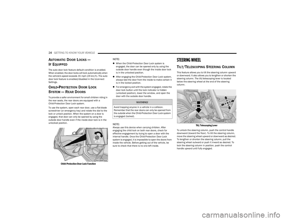
To use the system, open each rear door, use a flat-blade
screwdriver (or emergency key) and rotate the dial to the
lock or unlock position. When the system on a door is
engaged, that door can only be opened by using the
outside door handle even if the inside door lock is in the
unlocked position.
Child-Protection Door Lock Function
NOTE:
When the Child-Protection Door Lock system is
engaged, the door can be opened only by using the
outside door handle even though the inside door lock
is in the unlocked position.
After engaging the Child-Protection Door Lock system,
always test the door from the inside to make certain it
is in the locked position.
For emergency exit with the system engaged, rotate the
door lock button until the lock indicator is hidden
(unlocked position), lower the window, and open the
door with the outside door handle.
NOTE:Always use this device when carrying children. After
engaging the child lock on both rear doors, check for
effective engagement by trying to open a door with the
internal handle. Once the Child-Protection Door Lock
system is engaged, it is impossible to open the doors from
inside the vehicle. Before getting out of the vehicle, be
sure to check that there is no one left inside.
STEERING WHEEL
TILT/TELESCOPING STEERING COLUMN
This feature allows you to tilt the steering column upward
or downward. It also allows you to lengthen or shorten the
steering column. The tilt/telescoping lever is located
below the steering wheel at the end of the steering
column.
Tilt/Telescoping Lever
To unlock the steering column, push the control handle
downward (toward the floor). To tilt the steering column,
move the steering wheel upward or downward as desired.
To lengthen or shorten the steering column, pull the
steering wheel outward or push it inward as desired. To
lock the steering column in position, push the control
handle upward until fully engaged.
WARNING!
Avoid trapping anyone in a vehicle in a collision.
Remember that the rear doors can only be opened from
the outside when the Child-Protection Door Lock system
is engaged (locked).
23_KL_OM_EN_USC_t.book Page 24
Page 35 of 276
GETTING TO KNOW YOUR VEHICLE33
Rear Head Restraints
The rear outboard head restraints have two positions: up
and down. The center head restraint has three positions:
up, mid, and down. When the center seat is being
occupied the head restraint should be adjusted to the
occupant. When there is no occupant in the center seat,
the head restraint can be lowered for maximum visibility
for the driver.
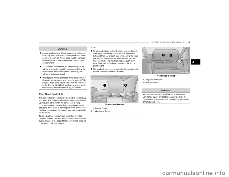
To raise the head restraint, pull upward on the head
restraint. To lower the head restraint, push the adjustment
button, located at the base of the head restraint, and push
downward on the head restraint.
NOTE:
To remove the head restraint, raise it as far as it can go.
Then, push the release button and the adjustment
button at the base of each post while pulling the head
restraint up. To reinstall the head restraint, put the
head restraint posts into the holes and push down -
ward. Then, adjust the head restraint to the appro -
priate height.
The seatback may need to be reclined in order to fully
remove the outboard head restraints.
Outboard Head Restraint Center Head Restraint
WARNING!
A loose head restraint thrown forward in a collision or
hard stop could cause serious injury or death to occu -
pants of the vehicle. Always securely stow removed
head restraints in a location outside the occupant
compartment.
ALL the head restraints MUST be reinstalled in the
vehicle to properly protect the occupants. Follow the
reinstallation instructions prior to operating the
vehicle or occupying a seat.
Do not place items over the top of the Reactive Head
Restraint, such as coats, seat covers or portable DVD
players. These items may interfere with the operation
of the Reactive Head Restraint in the event of a colli -
sion and could result in serious injury or death.
1 — Release Button
2 — Adjustment Button
1 — Adjustment Button
2 — Release Button
WARNING!
ALL the head restraints MUST be reinstalled in the
vehicle to properly protect the occupants. Follow the
reinstallation instructions prior to operating the vehicle
or occupying a seat.
2
23_KL_OM_EN_USC_t.book Page 33
Page 36 of 276
34GETTING TO KNOW YOUR VEHICLE
MIRRORS
INSIDE REARVIEW MIRROR
Auto Dimming Mirror
A single ball joint mirror is provided in the vehicle. It is a
twist on mirror that has a fixed position at the windshield.
The mirror installs on the windshield button with a
counterclockwise rotation and requires no tools for
mounting. The rearview mirror can be adjusted up, down,
left, and right. The mirror should be adjusted to center on
the view through the rear window.
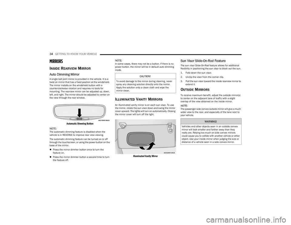
Automatic Dimming Button
NOTE:
The automatic dimming feature is disabled when the
vehicle is in REVERSE to improve rear view viewing.
The automatic dimming feature can be turned on or off
through the touchscreen, or using the power button on the
base of the mirror.
Press the mirror dimmer button once to turn the
feature on.
Press the mirror dimmer button a second time to turn
the feature off.
NOTE:In some cases, there may not be a button. If there is no
power button, the mirror will be in default auto dimming
mode.
ILLUMINATED VANITY MIRRORS
An illuminated vanity mirror is on each sun visor. To use
the mirror, rotate the sun visor down and swing the mirror
cover upward. The lights will turn on automatically. Closing
the mirror cover will turn off the light.
Illuminated Vanity Mirror
Sun Visor Slide-On-Rod Feature
The sun visor Slide-On-Rod feature allows for additional
flexibility in positioning the sun visor to block out the sun.
1. Fold down the sun visor.
2. Unclip the visor from the corner clip.
3. Pull the sun visor toward the inside rearview mirror to
extend it.
OUTSIDE MIRRORS
To receive maximum benefit, adjust the outside mirror(s)
to center on the adjacent lane of traffic with a slight
overlap of the view obtained on the inside mirror.
NOTE:The passenger side convex outside mirror will give a much
wider view to the rear, and especially of the lane next to
your vehicle.
CAUTION!
To avoid damage to the mirror during cleaning, never
spray any cleaning solution directly onto the mirror.
Apply the solution onto a clean cloth and wipe the
mirror clean.
WARNING!
Vehicles and other objects seen in an outside convex
mirror will look smaller and farther away than they
really are. Relying too much on side convex mirrors
could cause you to collide with another vehicle or other
object. Use your inside mirror when judging the size or
distance of a vehicle seen in a side convex mirror.
23_KL_OM_EN_USC_t.book Page 34
Page 42 of 276
40GETTING TO KNOW YOUR VEHICLE
DAYTIME RUNNING LIGHTS (DRLS) —
I
F EQUIPPED
The Daytime Running Lights will turn on when the engine
is started and remain on unless the headlamps are turned
on, the parking brake is applied, or the ignition is placed in
the OFF position.
NOTE:
For vehicles sold in Canada, the Daytime Running
Lights will automatically deactivate when the front fog
lights are turned on.
If allowed by law in the country in which the vehicle was
purchased, the Daytime Running Lights can be turned
on and off using the Uconnect system
Úpage 126.
On some vehicles, the Daytime Running Lights may
deactivate, or reduce intensity, on one side of the
vehicle (when a turn signal is activated on that side), or
on both sides of the vehicle (when the hazard warning
lights are activated).
HIGH/LOW BEAM SWITCH
After the low beam headlights are turned on, push the
multifunction lever, located on the left side of the steering
wheel, away from you to switch the headlights to high
beam. Pulling the multifunction lever back will turn the low
beams on.
AUTOMATIC HIGH BEAM HEADLAMP
C
ONTROL — IF EQUIPPED
The Automatic High Beam Headlamp Control system
provides increased forward lighting at night by automatically controlling the high beams through the use
of a camera mounted on the windshield. This camera
detects vehicle specific light and automatically switches
from high beams to low beams until the approaching
vehicle is out of view.
NOTE:
The Automatic High Beam Headlamp Control is
enabled through the Uconnect system Úpage 126.
The multifunction lever must be in the high beam posi -
tion and the low beams must be turned on in order to
activate the Automatic High Beams.
Broken, muddy, or obstructed headlights and taillights
of vehicles in the field of view will cause headlights to
remain on longer (closer to the vehicle). Also, dirt, film,
and other obstructions on the windshield or camera
lens will cause the system to function improperly.
When set to AUTO, and the low beams are on and the
multifunction lever is in the high beam position, the
system automatically turns the high beams on or off
based on light levels of the approaching vehicles.
Vehicle speed must be greater than 22 mph (35 km/h)
to activate Automatic High Beams. Once activated,
Automatic High Beams will remain on until the speed
falls below 15 mph (25 km/h).
FLASH-TO-PASS
You can signal another vehicle with your headlights by
lightly pulling the multifunction lever toward you. This will
cause the high beam headlights to turn on, and remain on,
until the lever is released.
AUTOMATIC HEADLIGHTS — IF EQUIPPED
This system automatically turns the headlights on or off
according to ambient light levels. To turn the system on,
rotate the headlight switch to the AUTO position for
automatic headlight operation. When the system is on, the
headlight time delay feature is also on. This means the
headlights will stay on for up to 90 seconds (depending on
customer programmable time of 30, 60, or 90 seconds)
after you place the ignition in the OFF position. To turn the
automatic system off, move the headlight switch out of the
AUTO position.
NOTE:The engine must be running before the headlights will
come on in the automatic mode.
PARKING LIGHTS
Rotate the headlight switch clockwise to the first detent
for parking lights and instrument panel lights operation.
Rotate the headlight switch to the second detent for
headlights, parking lights and instrument panel lights
operation.
NOTE:Vehicles sold in Canada are equipped with a headlight
switch with an AUTO and ON detent but without an OFF
detent. Headlights will be deactivated when the headlight
switch is placed in the parking lights position. However,
the Daytime Running Lights (DRLs) will be activated along
with the front and rear marker lights. The DRLs may be
deactivated when the parking brake is engaged.
23_KL_OM_EN_USC_t.book Page 40
Page 46 of 276
44GETTING TO KNOW YOUR VEHICLE
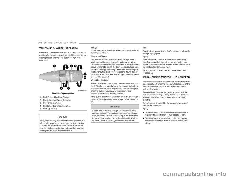
WINDSHIELD WIPER OPERATION
Rotate the end of the lever to one of the first four detent
positions for intermittent settings, the fifth detent for low
wiper operation and the sixth detent for high wiper
operation.
Windshield Wiper Operation
NOTE:
Do not operate the windshield wipers with the blades lifted
from the windshield.
Intermittent Wipers
Use one of the four intermittent wiper settings when
weather conditions make a single wiping cycle, with a
variable delay between cycles, desirable. At driving speeds
above 10 mph (16 km/h), the delay can be regulated from
a maximum of approximately 18 seconds between cycles
(first detent), to a cycle every one second (fourth detent).
If the vehicle is moving less than 10 mph (16 km/h), delay
times will be doubled.
Windshield Washers
To use the washer, pull the lever rearward toward you and
hold. If the lever is pulled while in the intermittent setting,
the wipers will turn on and operate for several wipe cycles
after the lever is released, and then resume the
intermittent interval previously selected.
If the lever is pulled while the wipers are in the off position,
the wipers will operate for several wipe cycles, then turn
off. Mist
Push the lever upward to the MIST position and release for
a single wiping cycle.
NOTE:The mist feature does not activate the washer pump;
therefore, no washer fluid will be sprayed on the wind
-
shield. The washer function must be used in order to spray
the windshield with washer fluid.
For information on wiper care and replacement, see
Úpage 219.
RAIN SENSING WIPERS — IF EQUIPPED
This feature senses rain or snowfall on the windshield and
automatically activates the wipers. Rotate the end of the
multifunction lever to one of four detent positions to
activate this feature.
The sensitivity of the system can be adjusted with the
multifunction lever. Wiper delay detent one is the least
sensitive, and wiper delay position four is the most
sensitive.
Setting three is preferred by the average driver during
normal rain conditions.
NOTE:
The Rain Sensing feature will not operate when the
wiper switch is in the low or high-speed position.
The Rain Sensing feature may not function properly
when ice or dried salt water is present on the wind -
shield.
1 — Push Forward For Rear Washer
2 — Rotate For Front Wiper Operation
3 — Pull For Front Washer
4 — Rotate For Rear Wiper Operation
5 — Push Up For Mist
CAUTION!
Always remove any buildup of snow that prevents the
windshield wiper blades from returning to the parked
position. If the windshield wiper switch is turned off,
and the blades cannot return to the parked position,
damage to the wiper motor may occur.
WARNING!
Sudden loss of visibility through the windshield could
lead to a collision. You might not see other vehicles or
other obstacles. To avoid sudden icing of the windshield
during freezing weather, warm the windshield with the
defroster before and during windshield washer use.
23_KL_OM_EN_USC_t.book Page 44
Page 49 of 276
GETTING TO KNOW YOUR VEHICLE47
Driver And Passenger Temperature Up And
Down Buttons
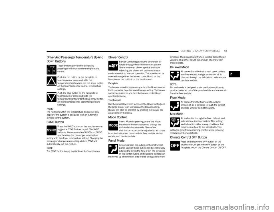
These buttons provide the driver and
passenger with independent temperature
control.
Push the red button on the faceplate or
touchscreen or press and slide the
temperature bar towards the red arrow button
on the touchscreen for warmer temperature
settings.
Push the blue button on the faceplate or
touchscreen or press and slide the
temperature bar towards the blue arrow button
on the touchscreen for cooler temperature
settings.
NOTE:The numbers within the temperature display will only
appear if the system is equipped with an automatic
climate control system.
SYNC Button
Press the SYNC button on the touchscreen to
toggle the SYNC feature on/off. The SYNC
indicator illuminates when SYNC is on. SYNC
synchronizes the passenger temperature
setting with the driver temperature setting. Changing the
passenger’s temperature setting while in SYNC will
automatically exit this feature.
NOTE:The SYNC button is only available on the touchscreen.
Blower Control
Blower Control regulates the amount of air
forced through the climate control system.
There are seven blower speeds available.
Adjusting the blower will cause automatic
mode to switch to manual operation. The speeds can be
selected using either the blower control knob on the
faceplate or the buttons on the touchscreen.
Faceplate
The blower speed increases as you turn the blower control
knob clockwise from the lowest blower setting. The blower
speed decreases as you turn the blower control knob
counterclockwise.
Touchscreen
Use the small blower icon to reduce the blower setting and
the large blower icon to increase the blower setting.
Blower can also be selected by pressing the blower bar
area between the icons.
Mode Control
Select Mode by pressing one of the Mode
buttons on the touchscreen to change the
airflow distribution mode. The airflow
distribution mode can be adjusted so air comes
from the instrument panel outlets, floor outlets, defrost
outlets, and demist outlets.
Panel Mode
Air comes from the outlets in the instrument
panel. Each of these outlets can be individually
adjusted to direct the flow of air. The air vanes
of the center outlets and outboard outlets can
be moved up and down or side to side to regulate airflow direction. There is a shut-off wheel located below the air
vanes to shut off or adjust the amount of airflow from
these outlets.
Bi-Level Mode
Air comes from the instrument panel outlets
and floor outlets. A slight amount of air is
directed through the defrost and side window
demister outlets.
NOTE:Bi-Level mode is designed under comfort conditions to
provide cooler air out of the panel outlets and warmer air
from the floor outlets.
Floor Mode
Air comes from the floor outlets. A slight
amount of air is directed through the defrost
and side window demister outlets.
Mix Mode
Air is directed through the floor, defrost, and
side window demister outlets. This setting
works best in cold or snowy conditions that
require extra heat to the windshield. This
setting is good for maintaining comfort while reducing
moisture on the windshield.
Climate Control OFF Button
Press and release the OFF button on the
touchscreen, or push the OFF button on the
faceplate to turn the Climate Control ON/OFF.
2
23_KL_OM_EN_USC_t.book Page 47
Page 52 of 276
50GETTING TO KNOW YOUR VEHICLE
Console Storage Compartment
The center console has both an upper and lower storage
area which can hold cell phones, PDAs, and other small
items.
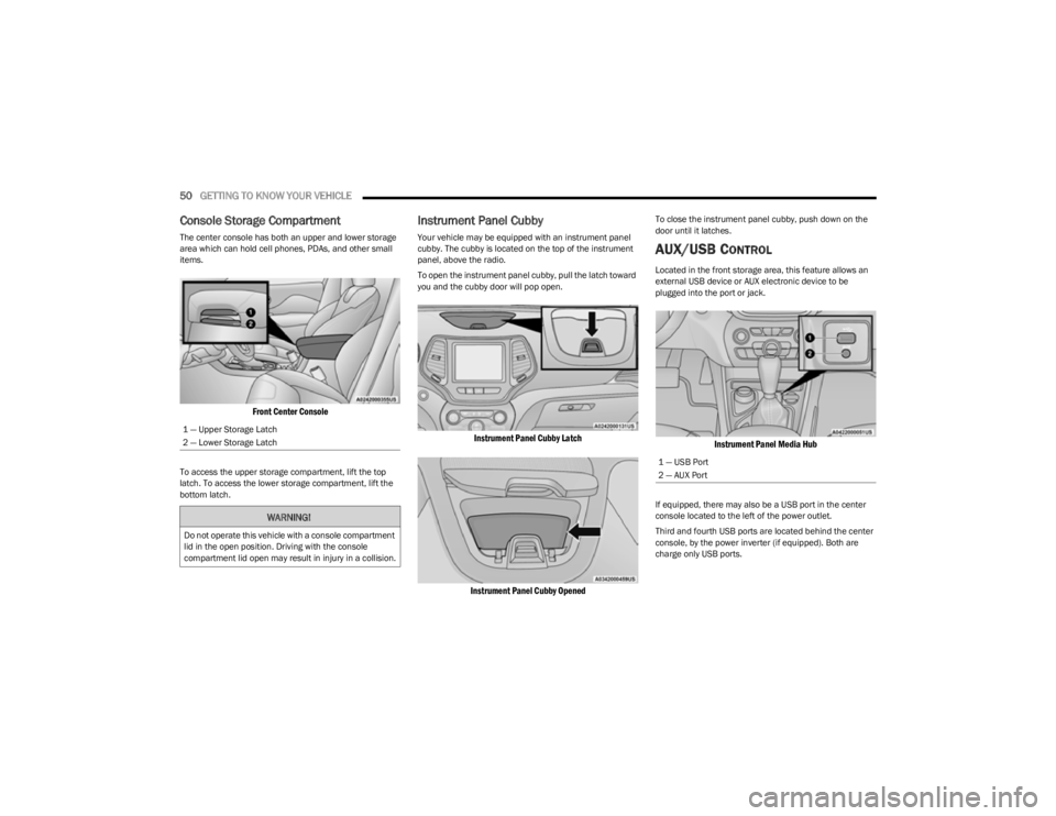
Front Center Console
To access the upper storage compartment, lift the top
latch. To access the lower storage compartment, lift the
bottom latch.
Instrument Panel Cubby
Your vehicle may be equipped with an instrument panel
cubby. The cubby is located on the top of the instrument
panel, above the radio.
To open the instrument panel cubby, pull the latch toward
you and the cubby door will pop open.
Instrument Panel Cubby Latch
Instrument Panel Cubby Opened
To close the instrument panel cubby, push down on the
door until it latches.
AUX/USB CONTROL
Located in the front storage area, this feature allows an
external USB device or AUX electronic device to be
plugged into the port or jack.
Instrument Panel Media Hub
If equipped, there may also be a USB port in the center
console located to the left of the power outlet.
Third and fourth USB ports are located behind the center
console, by the power inverter (if equipped). Both are
charge only USB ports.
1 — Upper Storage Latch
2 — Lower Storage LatchWARNING!
Do not operate this vehicle with a console compartment
lid in the open position. Driving with the console
compartment lid open may result in injury in a collision.
1 — USB Port
2 — AUX Port
23_KL_OM_EN_USC_t.book Page 50