change wheel JEEP CHEROKEE 2023 Owners Manual
[x] Cancel search | Manufacturer: JEEP, Model Year: 2023, Model line: CHEROKEE, Model: JEEP CHEROKEE 2023Pages: 276, PDF Size: 12.55 MB
Page 4 of 276
2
INTRODUCTION
SYMBOLS KEY ....................................................................... 8
ROLLOVER WARNING ......................................................... 8
VEHICLE MODIFICATIONS/ALTERATIONS ........................ 8
SYMBOL GLOSSARY ............................................................. 9
GETTING TO KNOW YOUR VEHICLE
KEYS ....................................................................................13Key Fob ........................................................................ 13
SENTRY KEY ........................................................................16
IGNITION SWITCH ...............................................................16 Ignition Node Module (IGNM) —
If Equipped .................................................................. 16
Keyless Enter ‘n Go™ Ignition
(If Equipped) ................................................................ 16
REMOTE START — IF EQUIPPED .......................................18 How To Use Remote Start .......................................... 18
To Exit Remote Start Mode ........................................ 18
Remote Start Front Defrost Activation —
If Equipped .................................................................. 19
Remote Start Comfort Systems —
If Equipped ................................................................. 19
Remote Start Windshield Wiper De-Icer
Activation — If Equipped ............................................. 19
Remote Start Cancel Message .................................. 19
VEHICLE SECURITY SYSTEM — IF EQUIPPED ..................20 To Arm The System .................................................... 20
To Disarm The System ............................................... 20
Rearming Of The System ............................................ 20
Security System Manual Override.............................. 20 DOORS ................................................................................ 20
Manual Door Locks......................................................20
Power Door Locks .......................................................21
Keyless Enter ‘n Go™ — Passive Entry ....................... 22
Automatic Unlock Doors On Exit ................................. 23
Automatic Door Locks — If Equipped ........................ 24
Child-Protection Door Lock System — Rear Doors .... 24
STEERING WHEEL............................................................... 24 Tilt/Telescoping Steering Column ..............................24
Heated Steering Wheel — If Equipped ....................... 25
UCONNECT VOICE RECOGNITION ..................................... 25 Introducing Voice Recognition .................................... 25
Basic Voice Commands............................................... 25
Get Started ................................................................... 26
Additional Information................................................. 26
DRIVER MEMORY SETTINGS — IF EQUIPPED ................ 26 Programming The Memory Feature............................ 27
Linking And Unlinking The Key Fob To Memory......... 27
Memory Position Recall............................................... 27
SEATS .................................................................................. 28 Manual Adjustment
(Front Seats) — If Equipped......................................... 28
Manual Adjustment (Rear Seats) ............................... 29
Power Adjustment (Front Seats) — If Equipped ......... 30
Heated Seats — If Equipped........................................ 31
Ventilated Seats — If Equipped................................... 32
Head Restraints ........................................................... 32
MIRRORS ............................................................................ 34 Inside Rearview Mirror ................................................ 34
Illuminated Vanity Mirrors ........................................... 34
Outside Mirrors ........................................................... 34
Outside Mirrors With Turn Signal And Approach
Lighting — If Equipped ................................................. 35
Power Mirrors...............................................................35
Heated Mirrors — If Equipped .................................... 35 UNIVERSAL GARAGE DOOR OPENER
(HOMELINK®) — IF EQUIPPED
S
................................... 35
Before You Begin Programming HomeLink® ............ 36
Erasing All The HomeLink® Channels ....................... 36
Identifying Whether You Have A Rolling Code Or
Non-Rolling Code Device............................................. 36
Programming HomeLink® To A Garage Door
Opener ......................................................................... 36
Programming HomeLink® To A Miscellaneous
Device .......................................................................... 37
Reprogramming A Single HomeLink® Button ........... 37
Canadian/Gate Operator Programming .................... 37
Security ........................................................................ 38
Troubleshooting Tips ................................................... 38
EXTERIOR LIGHTS .............................................................. 39 Multifunction Lever .................................................... 39
Headlight Switch.......................................................... 39
Daytime Running Lights (DRLs) — If Equipped .......... 40
High/Low Beam Switch............................................... 40
Automatic High Beam Headlamp Control —
If Equipped .................................................................. 40
Flash-To-Pass............................................................... 40
Automatic Headlights — If Equipped ......................... 40
Parking Lights .............................................................. 40
Automatic Headlights With
Wipers — If Equipped .................................................. 41
Headlight Time Delay .................................................. 41
Lights-On Reminder .................................................... 41
Fog Lights — If Equipped ............................................. 41
Turn Signals ................................................................. 42
Lane Change Assist — If Equipped ............................. 42
Battery Saver ............................................................... 42
INTERIOR LIGHTS ............................................................... 42 Interior Courtesy Lights ............................................... 42
Illuminated Entry ........................................................ 43
23_KL_OM_EN_USC_t.book Page 2
Page 9 of 276
7
INTRODUCTION
Dear Customer,
Congratulations on the purchase of your new Jeep®. Be assured that it represents precision workmanship, distinctive styling, and high quality.
This is a specialized utility vehicle. It can go places and perform tasks that are not intended for conventional passenger vehicles. It handles and maneuvers differently from many
passenger vehicles both on-road and off-road, so take time to become familiar with your vehicle. If equipped, the two-wheel drive version of this vehicle was designed for on-road use
only. It is not intended for off-road driving or use in other severe conditions suited for a four-wheel drive vehicle. Before you drive this vehicle, read the Owner’s Manual. Be sure you are
familiar with all vehicle controls, particularly those used for braking, steering, transmission, and transfer case shifting. Learn how your vehicle handles on different road surfaces. Your
driving skills will improve with experience. When driving off-road, or working the vehicle, don’t overload the vehicle or expect the vehicle to overcome the natural laws of physics. Always
observe federal, state, provincial and local laws wherever you drive. As with other vehicles of this type, failure to operate this vehicle correctly may result in loss of control or a collision
Úpage 123.
This Owner's Manual has been prepared with the assistance of service and engineering specialists to acquaint you with the operation and maintenance of your vehicle. It is
supplemented by customer-oriented documents. Within this information, you will find a description of the services that FCA US LLC offers to its customers as well as the details of the
terms and conditions for maintaining its validity. Please take the time to read all of these publications carefully before driving your vehicle for the first time. Following the instructions,
recommendations, tips, and important warnings in this manual will help ensure safe and enjoyable operation of your vehicle.
This Owner’s Manual describes all versions of this vehicle. Options and equipment dedicated to specific markets or versions are not expressly indicated in the text. Therefore, you should
only consider the information that is related to the trim level, engine, and version that you have purchased. Any content introduced throughout the Owner’s Information, which may or
may not be applicable to your vehicle, will be identified with the wording “If Equipped”. All data contained in this publication are intended to help you use your vehicle in the best possible
way. FCA US LLC aims at a constant improvement of the vehicles produced. For this reason, it reserves the right to make changes to the model described for technical and/or commercial
reasons. For further information, contact an authorized dealer.
When it comes to service, remember that authorized dealers know your Jeep® best, have factory-trained technicians, genuine Mopar® parts, and care about your satisfaction.
1
23_KL_OM_EN_USC_t.book Page 7
Page 21 of 276

GETTING TO KNOW YOUR VEHICLE19
The Remote Start system will turn the engine off if the
Remote Start button on the key fob is pushed again, or if
the engine is allowed to run for the entire 15 minute cycle.
Once the driver’s door is opened, or the ignition is placed
in the ON/RUN position, the climate controls will resume
previously set operations (temperature, blower control,
etc.).
NOTE:
For vehicles equipped with the Keyless Enter ‘n Go™ —
Passive Entry feature, the message “Remote Start
Active — Push Start Button” will show in the instrument
cluster display until you push the START/STOP ignition
button.
To avoid unintentional shutdowns, the system will
disable for two seconds after receiving a valid Remote
Start request.
REMOTE START FRONT DEFROST
A
CTIVATION — IF EQUIPPED
When Remote Start is active, and the outside ambient
temperature is 40°F (4.5°C) or below, the system will
automatically activate front defrost for 15 minutes or less.
The timing is dependent on the ambient temperature.
Once the timer expires, the system will automatically
adjust the settings depending on ambient conditions. See
“Remote Start Comfort Systems — If Equipped” in the next
section for detailed operation.
REMOTE START COMFORT SYSTEMS —
I
F EQUIPPED
When Remote Start is activated, the front and rear defrost
will automatically turn on in cold weather. The heated steering wheel and driver heated seat feature will turn on
if selected in the Comfort menu screen within Uconnect
Settings
Úpage 126. In warm weather, the driver vented
seat feature will automatically turn on when the Remote
Start is activated, if programmed in the Comfort menu
screen. The vehicle will adjust the climate control settings
depending on the outside ambient temperature.
Automatic Temperature Control (ATC) — If Equipped
The climate controls automatically adjust to the optimal
temperature and mode settings dependent on the outside
ambient temperature. This will occur until the driver’s door
is opened, or the ignition is placed in the ON/RUN position,
where the climate controls will resume their previous
settings.
Manual Temperature Control (MTC) — If Equipped
In ambient temperatures at 40°F (4.5°C) or below, the
climate settings will default to maximum heat, with
fresh air entering the cabin. If the front defrost timer
expires, the vehicle will enter Mix Mode.
In ambient temperatures from 40°F (4.5°C) to 78°F
(26°C), the climate settings will be based on the last
settings selected by the driver.
In ambient temperatures at 78°F (26°C) or above, the
climate settings will default to MAX A/C, Bi-Level Mode,
and Recirculation on.
For more information on ATC, MTC, and climate control
settings, see
Úpage 45.
NOTE:These features will stay on through the duration of Remote
Start until the driver’s door is opened, or until the ignition
is placed in the ON/RUN position. The climate control
settings will change if manually adjusted by the driver while the vehicle is in Remote Start mode, and exit auto
-
matic override. This includes the OFF button on the
climate controls, which will turn the system off.
REMOTE START WINDSHIELD WIPER
D
E-ICER ACTIVATION — IF EQUIPPED
When Remote Start is active and the outside ambient
temperature is less than 33°F (0.6°C), the Windshield
Wiper De-Icer will activate. Exiting Remote Start will
resume its previous operation. If the Windshield Wiper
De-Icer was active, the timer and operation will continue.
REMOTE START CANCEL MESSAGE
One of the following messages will display in the
instrument cluster display if the vehicle fails to remote
start, or exits Remote Start prematurely:
Remote Start Canceled — Door Open
Remote Start Canceled — Hood Open
Remote Start Canceled — Fuel Low
Remote Start Canceled — Liftgate Open
Remote Start Disabled — Start Vehicle To Reset
Remote Start Canceled — Too Cold
Remote Start Canceled — Time Expired
The message will stay active until the ignition is placed in
the ON/RUN position.
2
23_KL_OM_EN_USC_t.book Page 19
Page 49 of 276
GETTING TO KNOW YOUR VEHICLE47
Driver And Passenger Temperature Up And
Down Buttons
These buttons provide the driver and
passenger with independent temperature
control.
Push the red button on the faceplate or
touchscreen or press and slide the
temperature bar towards the red arrow button
on the touchscreen for warmer temperature
settings.
Push the blue button on the faceplate or
touchscreen or press and slide the
temperature bar towards the blue arrow button
on the touchscreen for cooler temperature
settings.
NOTE:The numbers within the temperature display will only
appear if the system is equipped with an automatic
climate control system.
SYNC Button
Press the SYNC button on the touchscreen to
toggle the SYNC feature on/off. The SYNC
indicator illuminates when SYNC is on. SYNC
synchronizes the passenger temperature
setting with the driver temperature setting. Changing the
passenger’s temperature setting while in SYNC will
automatically exit this feature.
NOTE:The SYNC button is only available on the touchscreen.
Blower Control
Blower Control regulates the amount of air
forced through the climate control system.
There are seven blower speeds available.
Adjusting the blower will cause automatic
mode to switch to manual operation. The speeds can be
selected using either the blower control knob on the
faceplate or the buttons on the touchscreen.
Faceplate
The blower speed increases as you turn the blower control
knob clockwise from the lowest blower setting. The blower
speed decreases as you turn the blower control knob
counterclockwise.
Touchscreen
Use the small blower icon to reduce the blower setting and
the large blower icon to increase the blower setting.
Blower can also be selected by pressing the blower bar
area between the icons.
Mode Control
Select Mode by pressing one of the Mode
buttons on the touchscreen to change the
airflow distribution mode. The airflow
distribution mode can be adjusted so air comes
from the instrument panel outlets, floor outlets, defrost
outlets, and demist outlets.
Panel Mode
Air comes from the outlets in the instrument
panel. Each of these outlets can be individually
adjusted to direct the flow of air. The air vanes
of the center outlets and outboard outlets can
be moved up and down or side to side to regulate airflow direction. There is a shut-off wheel located below the air
vanes to shut off or adjust the amount of airflow from
these outlets.
Bi-Level Mode
Air comes from the instrument panel outlets
and floor outlets. A slight amount of air is
directed through the defrost and side window
demister outlets.
NOTE:Bi-Level mode is designed under comfort conditions to
provide cooler air out of the panel outlets and warmer air
from the floor outlets.
Floor Mode
Air comes from the floor outlets. A slight
amount of air is directed through the defrost
and side window demister outlets.
Mix Mode
Air is directed through the floor, defrost, and
side window demister outlets. This setting
works best in cold or snowy conditions that
require extra heat to the windshield. This
setting is good for maintaining comfort while reducing
moisture on the windshield.
Climate Control OFF Button
Press and release the OFF button on the
touchscreen, or push the OFF button on the
faceplate to turn the Climate Control ON/OFF.
2
23_KL_OM_EN_USC_t.book Page 47
Page 50 of 276
48GETTING TO KNOW YOUR VEHICLE
AUTOMATIC TEMPERATURE CONTROL
(ATC) — I
F EQUIPPED
Automatic Operation
1. Push the AUTO button on the faceplate, or the AUTO
button on the touchscreen on the Automatic
Temperature Control (ATC) Panel.
2. Next, adjust the temperature that you would like the system to maintain by adjusting the driver and
passenger temperature control buttons. Once the
desired temperature is displayed, the system will
achieve and automatically maintain that comfort
level.
3. When the system is set up for your comfort level, it is not necessary to change the settings. You will
experience the greatest efficiency by simply allowing
the system to function automatically.
NOTE:
It is not necessary to move the temperature settings for
cold or hot vehicles. The system automatically adjusts
the temperature, mode, and blower speed to provide
comfort as quickly as possible.
The temperature can be displayed in U.S. or Metric
units by selecting the US/Metric customer-program -
mable feature within the Uconnect system
Úpage 126.
To provide you with maximum comfort in the Automatic
mode during cold start-ups, the blower fan will remain on
low until the engine warms up. The blower will increase in
speed and transition into Auto mode.
Manual Operation Override
This system offers a full complement of manual override
features. The AUTO symbol in the front ATC display will be
turned off when the system is being used in the manual
mode.
CLIMATE VOICE COMMANDS
Adjust vehicle temperatures hands-free and keep
everyone comfortable while you keep moving ahead.
Push the VR button on the steering wheel. After the beep,
say one of the following commands:
“Set the driver temperature to 70 degrees ”
“Set the passenger temperature to 70 degrees ”
Did You Know: Voice Command for Climate may only be
used to adjust the interior temperature of your vehicle.
Voice Command will not work to adjust the heated seats
or steering wheel if equipped.
OPERATING TIPS
Refer to the chart at the end of this section for suggested
control settings for various weather conditions.
Summer Operation
The engine cooling system must be protected with a
high-quality antifreeze coolant to provide proper corrosion
protection and to protect against engine overheating. OAT
coolant (conforming to MS.90032) is recommended.
Winter Operation
To ensure the best possible heater and defroster
performance, make sure the engine cooling system is
functioning properly and the proper amount, type, and concentration of coolant is used. Use of the Air
Recirculation mode during Winter months is not
recommended, because it may cause window fogging.
Vacation/Storage
For information on maintaining the Climate Control system
when the vehicle is being stored for an extended period of
time, see
Úpage 250.
Window Fogging
Vehicle windows tend to fog on the inside in mild, rainy,
and/or humid weather. To clear the windows, select
Defrost or Mix mode and increase the front blower speed.
Do not use the Recirculation mode without A/C for long
periods, as fogging may occur.
Outside Air Intake
Make sure the air intake, located directly in front of the
windshield, is free of obstructions, such as leaves. Leaves
collected in the air intake may reduce airflow, and if they
enter the air distribution box, they could plug the water
drains. In Winter months, make sure the air intake is clear
of ice, slush, and snow.
Cabin Air Filter
The Climate Control system filters out dust and pollen
from the air. Contact an authorized dealer to service your
cabin air filter, and to have it replaced when needed.
Stop/Start System — If Equipped
While in an Autostop, the Climate Control system may
automatically adjust airflow to maintain cabin comfort.
Customer settings will be maintained upon return to an
engine running condition.
23_KL_OM_EN_USC_t.book Page 48
Page 66 of 276
64GETTING TO KNOW YOUR INSTRUMENT PANEL
The instrument cluster display menu items may consist of
the following:
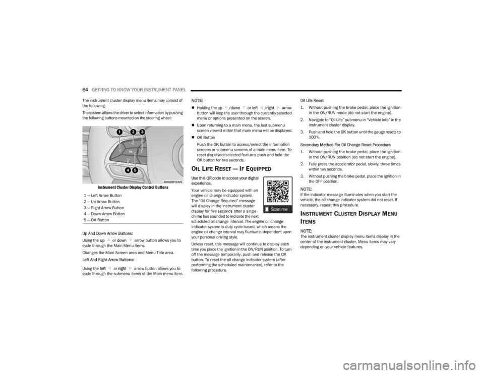
The system allows the driver to select information by pushing
the following buttons mounted on the steering wheel:
Instrument Cluster Display Control Buttons
Up And Down Arrow Buttons:
Using the up or down arrow button allows you to
cycle through the Main Menu Items.
Changes the Main Screen area and Menu Title area.
Left And Right Arrow Buttons:
Using the left or right arrow button allows you to
cycle through the submenu items of the Main menu item.
NOTE:
Holding the up /down or left /right arrow
button will loop the user through the currently selected
menu or options presented on the screen.
Upon returning to a main menu, the last submenu
screen viewed within that main menu will be displayed.
OK Button
Push the OK button to access/select the information
screens or submenu screens of a main menu item. To
reset displayed/selected features push and hold the
OK button for two seconds.
OIL LIFE RESET — IF EQUIPPED
Use this QR code to access your digital
experience.
Your vehicle may be equipped with an
engine oil change indicator system.
The “Oil Change Required” message
will display in the instrument cluster
display for five seconds after a single
chime has sounded to indicate the next
scheduled oil change interval. The engine oil change
indicator system is duty cycle based, which means the
engine oil change interval may fluctuate, dependent upon
your personal driving style.
Unless reset, this message will continue to display each
time you place the ignition in the ON/RUN position. To turn
off the message temporarily, push and release the OK
button. To reset the oil change indicator system (after
performing the scheduled maintenance), refer to the
following procedure. Oil Life Reset
1. Without pushing the brake pedal, place the ignition
in the ON/RUN mode (do not start the engine).
2. Navigate to “Oil Life” submenu in “Vehicle Info” in the instrument cluster display.
3. Push and hold the OK button until the gauge resets to
100%.
Secondary Method For Oil Change Reset Procedure
1. Without pushing the brake pedal, place the ignition in the ON/RUN position (do not start the engine).
2. Fully press the accelerator pedal, slowly, three times within ten seconds.
3. Without pushing the brake pedal, place the ignition in the OFF position.
NOTE:If the indicator message illuminates when you start the
vehicle, the oil change indicator system did not reset. If
necessary, repeat this procedure.
INSTRUMENT CLUSTER DISPLAY MENU
I
TEMS
NOTE:The instrument cluster display menu items display in the
center of the instrument cluster. Menu items may vary
depending on your vehicle features.
1 — Left Arrow Button
2 — Up Arrow Button
3 — Right Arrow Button
4 — Down Arrow Button
5 — OK Button
23_KL_OM_EN_USC_t.book Page 64
Page 67 of 276
GETTING TO KNOW YOUR INSTRUMENT PANEL65
Speedometer
Push and release the up or down arrow button
until the speedometer menu icon is displayed in the
instrument cluster display. Push and release the OK
button to toggle units, mph or km/h (If Equipped), of the
speedometer.
Vehicle Info
Push and release the up or down arrow button
until the Vehicle Info menu icon is displayed in the
instrument cluster display. Push and release the left or
right arrow button to scroll through the information
submenus and push and release the OK button to select
or reset the submenus.
Tire Pressure : This menu option will display the current
tire pressure. A low tire will be highlighted in red for the
7 inch cluster and it will be highlighted in white text for
the 3.5 inch cluster.
Coolant Temperature : This menu option will display the
current coolant temperature of the vehicle.
Transmission Temperature : This menu will display the
current transmission temperature of the vehicle.
Oil Temperature : This menu option will display the
current oil temperature level of the vehicle.
Oil Life: This menu option will display the current oil life
of the vehicle.
Battery Voltage : This menu option will display the
current voltage level of the battery.
Driver Assist
Push and release the up or down arrow button
until the Driver Assist menu title is highlighted in the
instrument cluster display.
Adaptive Cruise Control (ACC) Menu — If Equipped
The instrument cluster display displays the current ACC
and LaneSense system settings. The information
displayed depends on the status of ACC and LaneSense.
Push the ACC on/off button (located on the steering
wheel) until one of the following displays in the instrument
cluster display:
Adaptive Cruise Control Off
When ACC is deactivated, and LaneSense is OFF, the
display will read “Adaptive Cruise Control Off.”
Adaptive Cruise Control Ready
When ACC is activated but the vehicle speed setting has
not been selected, the display will read “Adaptive Cruise
Control Ready.”
Push and release the SET + or the SET- button (located on
the steering wheel) and the following will display in the
instrument cluster display:
ACC SET
When ACC is set, the set speed will display in the
instrument cluster.
The ACC screen may display once again if any ACC activity
occurs, which may include any of the following:
Distance Setting Change
System Cancel
Driver Override
System Off
ACC Proximity Warning
ACC Unavailable Warning
NOTE:The instrument cluster display will return to the last
display selected after five seconds of no ACC display
activity
Úpage 92.
LaneSense — If Equipped
The instrument cluster display displays the current
LaneSense system settings. The information displayed
depends on LaneSense system status and the conditions
that need to be met
Úpage 109.
Fuel Economy
Push and release the up or down arrow button
until the Fuel Economy menu title is displayed in the
instrument cluster display. Toggle the left or right
arrow button to select the screen with or without current
fuel economy display. Push and hold the OK button to
reset average fuel economy feature.
Range – The display shows the estimated distance (mi
or km) that can be traveled with the fuel remaining in
the tank. When the Range value is less than 10 miles
(16 km) estimated driving distance, the Range display
will change to a “LOW FUEL” message. Adding a signif -
icant amount of fuel to the vehicle will turn off the “LOW
FUEL” message and a new Range value will display.
Range cannot be reset through the OK button.
3
23_KL_OM_EN_USC_t.book Page 65
Page 112 of 276
110STARTING AND OPERATING
When only a single lane marking is detected and the driver
drifts across the lane marking (no turn signal applied), the
LaneSense system provides a visual warning through the
instrument cluster display to prompt the driver to remain
within the lane.
When only a single lane marking is detected, a haptic or a
torque warning will not be provided.
NOTE:When operating conditions have been met, the Lane -
Sense system will monitor if the driver’s hands are on the
steering wheel and provide an audible and visual warning
to the driver if removed. The system will cancel if the driver
does not return their hands to the wheel.
TURNING LANESENSE ON OR OFF
The LaneSense button is located on the switch
panel below the Uconnect display.
To turn the LaneSense system on, push the LaneSense
button (LED turns off). A “LaneSense On” message is
shown in the instrument cluster display.
To turn the LaneSense system off, push the LaneSense
button once (LED turns on).
NOTE:The LaneSense system will retain the last system state, on
or off, from the last ignition cycle when the ignition is
changed to the ON/RUN position.
LANESENSE WARNING MESSAGE
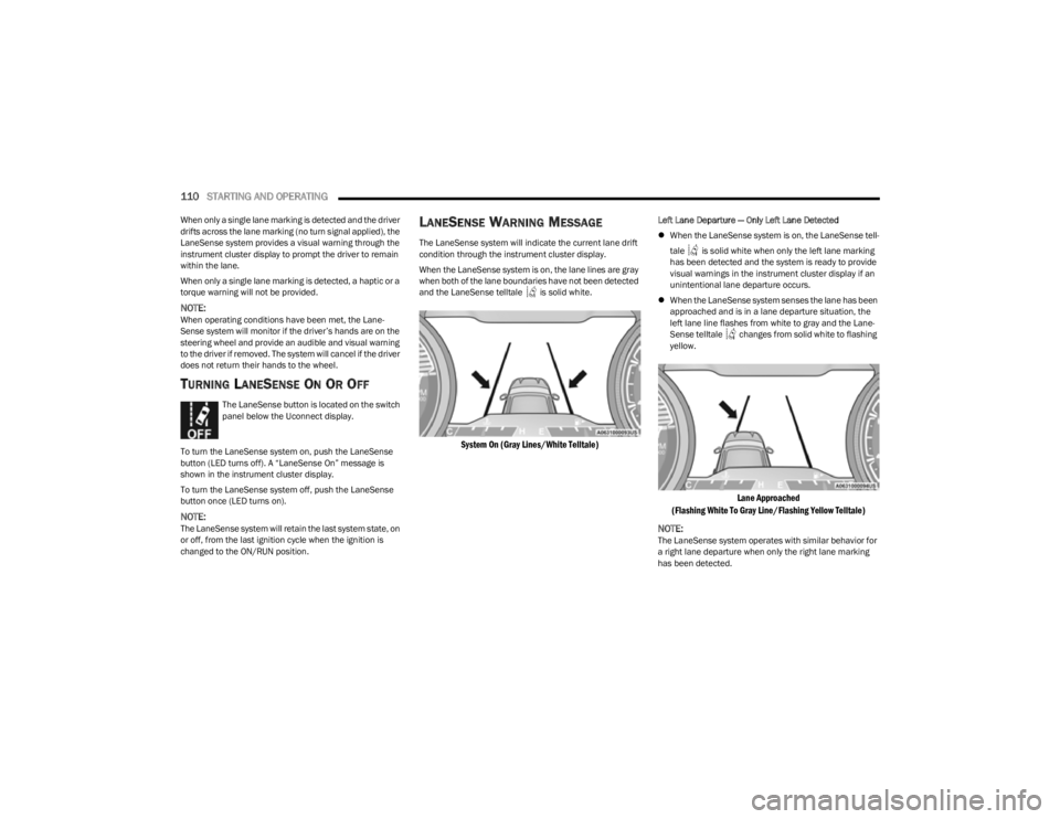
The LaneSense system will indicate the current lane drift
condition through the instrument cluster display.
When the LaneSense system is on, the lane lines are gray
when both of the lane boundaries have not been detected
and the LaneSense telltale is solid white.
System On (Gray Lines/White Telltale)
Left Lane Departure — Only Left Lane Detected
When the LaneSense system is on, the LaneSense tell -
tale is solid white when only the left lane marking
has been detected and the system is ready to provide
visual warnings in the instrument cluster display if an
unintentional lane departure occurs.
When the LaneSense system senses the lane has been
approached and is in a lane departure situation, the
left lane line flashes from white to gray and the Lane -
Sense telltale changes from solid white to flashing
yellow.
Lane Approached
(Flashing White To Gray Line/Flashing Yellow Telltale)
NOTE:
The LaneSense system operates with similar behavior for
a right lane departure when only the right lane marking
has been detected.
23_KL_OM_EN_USC_t.book Page 110
Page 113 of 276
STARTING AND OPERATING111
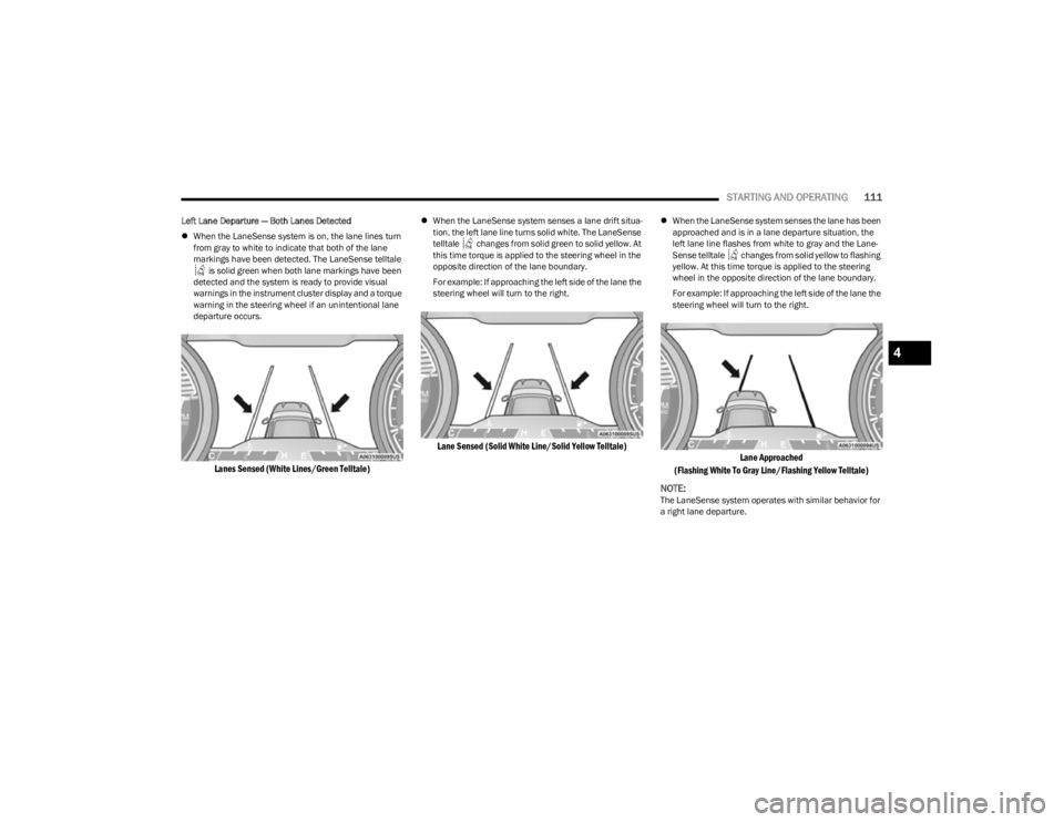
Left Lane Departure — Both Lanes Detected
When the LaneSense system is on, the lane lines turn
from gray to white to indicate that both of the lane
markings have been detected. The LaneSense telltale
is solid green when both lane markings have been
detected and the system is ready to provide visual
warnings in the instrument cluster display and a torque
warning in the steering wheel if an unintentional lane
departure occurs.
Lanes Sensed (White Lines/Green Telltale)
When the LaneSense system senses a lane drift situa -
tion, the left lane line turns solid white. The LaneSense
telltale changes from solid green to solid yellow. At
this time torque is applied to the steering wheel in the
opposite direction of the lane boundary.
For example: If approaching the left side of the lane the
steering wheel will turn to the right.
Lane Sensed (Solid White Line/Solid Yellow Telltale)
When the LaneSense system senses the lane has been
approached and is in a lane departure situation, the
left lane line flashes from white to gray and the Lane -
Sense telltale changes from solid yellow to flashing
yellow. At this time torque is applied to the steering
wheel in the opposite direction of the lane boundary.
For example: If approaching the left side of the lane the
steering wheel will turn to the right.
Lane Approached
(Flashing White To Gray Line/Flashing Yellow Telltale)
NOTE:
The LaneSense system operates with similar behavior for
a right lane departure.
4
23_KL_OM_EN_USC_t.book Page 111
Page 116 of 276
114STARTING AND OPERATING
Payload
The payload of a vehicle is defined as the allowable load
weight a truck can carry, including the weight of the driver,
all passengers, options and cargo.
Gross Axle Weight Rating (GAWR)
The GAWR is the maximum permissible load on the front
and rear axles. The load must be distributed in the cargo
area so that the GAWR of each axle is not exceeded.
Each axle GAWR is determined by the components in the
system with the lowest load carrying capacity (axle,
springs, tires or wheels). Heavier axles, or suspension
components sometimes specified by purchasers for
increased durability, do not necessarily increase the
vehicle's GVWR.
Tire Size
The tire size on the Vehicle Certification Label represents
the actual tire size on your vehicle. Replacement tires
must be equal to the load capacity of this tire size.
Rim Size
This is the rim size that is appropriate for the tire size
listed.
Inflation Pressure
This is the cold tire inflation pressure for your vehicle for
all loading conditions up to full GAWR.
Curb Weight
The curb weight of a vehicle is defined as the total weight
of the vehicle with all fluids, including vehicle fuel, at full
capacity conditions, and with no occupants or cargo
loaded into the vehicle. The front and rear curb weight
values are determined by weighing your vehicle on a
commercial scale before any occupants or cargo are
added.
Loading
The actual total weight and the weight of the front and rear
of your vehicle at the ground can best be determined by
weighing it when it is loaded and ready for operation.
The entire vehicle should first be weighed on a commercial
scale to ensure that the GVWR has not been exceeded.
The weight on the front and rear of the vehicle should then
be determined separately to be sure that the load is
properly distributed over the front and rear axle. Weighing
the vehicle may show that the GAWR of either the front or
rear axles has been exceeded but the total load is within
the specified GVWR. If so, weight must be shifted from
front to rear or rear to front as appropriate until the
specified weight limitations are met. Store the heavier
items down low and be sure that the weight is distributed
equally. Stow all loose items securely before driving.
Improper weight distributions can have an adverse effect
on the way your vehicle steers and handles and the way
the brakes operate.TRAILER TOWING
In this section you will find safety tips and information on
limits to the type of towing you can reasonably do with your
vehicle. Before towing a trailer, carefully review this
information to tow your load as efficiently and safely as
possible.
To maintain the New Vehicle Limited Warranty coverage,
follow the requirements and recommendations in this
manual concerning vehicles used for trailer towing.
COMMON TOWING DEFINITIONS
The following trailer towing related definitions will assist
you in understanding the following information:
Gross Vehicle Weight Rating (GVWR)
The GVWR is the total allowable weight of your vehicle.
This includes driver, passengers, cargo, and tongue
weight. The total load must be limited so that you do not
exceed the GVWR
Úpage 113.
WARNING!
Do not load your vehicle any heavier than the GVWR or
the maximum front and rear GAWR. If you do, parts on
your vehicle can break, or it can change the way your
vehicle handles. This could cause you to lose control.
Overloading can shorten the life of your vehicle.
23_KL_OM_EN_USC_t.book Page 114