belt JEEP CJ 1953 User Guide
[x] Cancel search | Manufacturer: JEEP, Model Year: 1953, Model line: CJ, Model: JEEP CJ 1953Pages: 376, PDF Size: 19.96 MB
Page 75 of 376
'Jeep'
UNIVERSAL SERIES
SERVICE
MANUAL
Dl
DAUNTLESS
V-6
ENGINE
Contents
SUBJECT
PAR.
SUBJEC
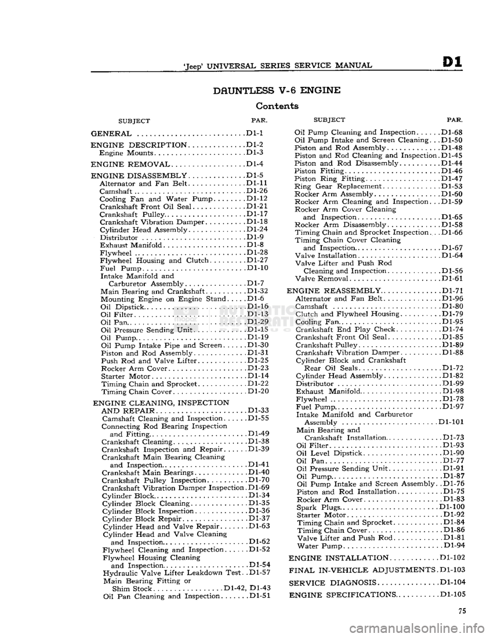
GENERAL
.... . . Dl-1 Oil Pump Cl(
ENGINE DESCRIPTION
D1-2
Engine
Mounts Dl-3
ENGINE REMOVAL
Dl-4
ENGINE DISASSEMBLY
Dl-5
Alternator
and Fan Belt Dl-11
Camshaft
.... Dl-26
Cooling Fan and Water Pump.
......
.Dl-12
Crankshaft
Front Oil Seal .Dl-21
Crankshaft
Pulley D1-17
Crankshaft
Vibration Damper Dl-18
Cylinder
Head Assembly Dl-24
Distributor
Dl-9
Exhaust
Manifold .Dl-8
Flywheel
Dl-28
Flywheel
Housing and
Clutch
Dl-27
Fuel
Pump. ... . .Dl-10
Intake
Manifold and
Carburetor
Assembly.
.............
.Dl-7
Main
Bearing and Crankshaft. Dl-32 Mounting Engine on Engine Stand. . . . .Dl-6
Oil
Dipstick. Dl-16
Oil
Filter
Dl-13
Oil
Pan.. ...
.......
.Dl-29
Oil
Pressure Sending Unit Dl-15
Oil
Pump Dl-19
Oil
Pump Intake Pipe and Screen Dl-30
Piston and Rod Assembly. Dl-31
Push
Rod and Valve
Lifter.
.Dl-25
Rocker
Arm Cover Dl-23
Starter
Motor Dl-14
Timing
Chain
and Sprocket Dl-22
Timing
Chain
Cover Dl-20
ENGINE CLEANING, INSPECTION AND REPAIR
. . ... .Dl-33
Camshaft
Cleaning and Inspection Dl-55
Connecting Rod Bearing Inspection
and
Fitting .Dl-49
Crankshaft
Cleaning Dl-38
Crankshaft
Inspection and Repair Dl-39
Crankshaft
Main Bearing Cleaning
and
Inspection Dl-41
Crankshaft
Main Bearings. Dl-40
Crankshaft
Pulley Inspection. Dl-70
Crankshaft
Vibration Damper Inspection. D1-69
Cylinder
Block .Dl-34
Cylinder
Block Cleaning Dl-35
Cylinder
Block Inspection Dl-36
Cylinder
Block Repair. .Dl-37
Cylinder
Head and Valve Repair .Dl-63
Cylinder
Head and Valve Cleaning
and
Inspection.. . .Dl-62
Flywheel
Cleaning and Inspection Dl-52
Flywheel
Housing Cleaning
and
Inspection Dl-54
Hydraulic
Valve
Lifter
Leakdown Test. .Dl-57
Main
Bearing Fitting or
Shim
Stock Dl-42, Dl-43
Oil
Pan Cleaning and Inspection .Dl-51
PAR.
and
Inspection. .... .Dl-68
Oil
Pump Intake and Screen Cleaning. . .Dl-50
Piston and Rod Assembly.
...........
.Dl-48
Piston and Rod Cleaning and Inspection.D1-45
Piston and Rod Disassembly Dl-44
Piston Fitting Dl-46
Piston Ring Fitting. .Dl-47
Ring
Gear
Replacement. .Dl-53
Rocker
Arm Assembly. Dl-60
Rocker
Arm Cleaning and Inspection. . .Dl-59
Rocker
Arm Cover Cleaning
and
Inspection D1-65
Rocker
Arm Disassembly .Dl-58
Timing
Chain
and Sprocket Inspection. . .Dl-66
Timing
Chain
Cover Cleaning
and
Inspection.. . Dl-67
Valve
Installation D1-64
Valve
Lifter
and Push Rod
Cleaning
and Inspection. . Dl-56
Valve
Removal Dl-61
ENGINE REASSEMBLY
Dl-71
Alternator
and Fan Belt Dl-96
Camshaft
Dl-80
Clutch
and Flywheel Housing Dl-79
Cooling Fan.. . .Dl-95
Crankshaft
End Play Check. . Dl-74
Crankshaft
Front Oil Seal Dl-85
Crankshaft
Pulley Dl-89
Crankshaft
Vibration Damper Dl-88
Cylinder
Block and Crankshaft
Rear
Oil Seals Dl-72
Cylinder
Head Assembly .Dl-82
Distributor
Dl-99
Exhaust
Manifold Dl-98
Flywheel
.Dl-78
Fuel
Pump.. .. . Dl-97
Intake
Manifold and Carburetor Assembly Dl-101
Main
Bearing and
Crankshaft
Installation
.
Dl-73
Oil
Filter
Dl-93
Oil
Level
Dipstick Dl-90
Oil
Pan Dl-77
Oil
Pressure Sending Unit Dl-91
Oil
Pump.. .Dl-87
Oil
Pump Intake and Screen Assembly. .Dl-76
Piston and Rod Installation Dl-75
Rocker
Arm Cover. Dl-83
Spark
Plugs.. Dl-100
Starter
Motor Dl-92
Timing
Chain
and Sprocket.
..........
.Dl-84
Timing
Chain
Cover Dl-86
Valve
Lifter
and Push Rod Dl-81
Water
Pump. Dl-94
ENGINE INSTALLATION
Dl-102
FINAL
IN-VEHICLE
ADJUSTMENTS.
D1-103
SERVICE
DIAGNOSIS
Dl-104
ENGINE SPECIFICATIONS
. .Dl-105 75
Page 77 of 376
'Jeep'
UNIVERSAL SERIES SERVICE
MANUAL
Dl
©©©©©©©©©
12697
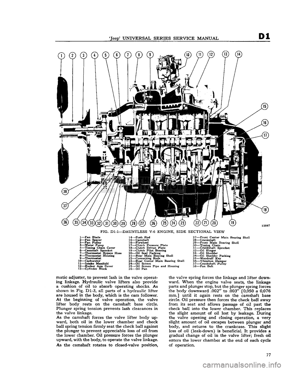
FIG.
Dl-1—DAUNTLESS
V-6
ENGINE, SIDE SECTIONAL VIEW
1—
Fan
Blade
2—
Fan
Spacer
3—Fan
Pulley
4—
Water
Pump 5—
Timing
Chain
Cover
6—
Camshaft
Sprocket
7—
Thermostat
Bypass Hose
8—
Thermostat
Housing
9—
Thermostat
10—
Carburetor
11—
Intake
Manifold
12—
Rocker
Arm Cover 13—
Cylinder
Block 14—
Push
Rod
15—
Camshaft
16—
Flywheel
17—
Clutch
Pressure Plate
18—
Clutch
Driven Plate
19—
Clutch
Pilot Bearing
20—
Oil
Seal Packing
21—
Rear
Main
Bearing Shell
22— Connecting Rods
23—
Rear
Center
Main
Bearing Shell
24—
Oil
Screen
25—
Oil
Screen Pipe and Housing
26—
Oil
Pan 27—
Front
Center
Main
Bearing Shell
28—
Crankshaft
29—
Front
Main
Bearing Shell
30—
Timing
Chain
31—
Crankshaft
Sprocket
32—
Oil
Slinger
33—
Oil
Shedder 34 Oil Shedder Packing
35—
-Woodruff
Key
36—
"Vibration
Damper
37—
Crankshaft
Pulley
38—
Fan
Belt matic adjuster, to prevent lash in the valve operat
ing linkage. Hydraulic valve lifters also provide
a
cushion of oil to absorb operating shocks. As shown in Fig. Dl-3, all parts of a hydraulic lifter
are
housed in the body, which is the cam follower.
At
the beginning of valve operation, the valve lifter body rests on the camshaft base circle.
Plunger
spring tension prevents lash clearances in the valve linkage.
As
the camshaft forces the valve lifter body up
ward,
both oil in the lower chamber and check
ball
spring
tension firmly seat the check ball against the plunger to prevent appreciable
loss
of oil from
the lower chamber. Oil pressure forces the plunger
upward,
with the body, to operate the valve linkage.
As
the camshaft rotates to closed-valve position, the valve spring forces the linkage and lifter down
ward.
When the
engine
valve seats, the linkage
parts
and plunger stop, but the plunger spring forces
the body downward .002" to .003"
[0,050
a
0,076
mm.] until it again rests on the camshaft base
circle.
Oil pressure then forces the check ball away
from
its seat and allows passage of oil past the check ball into the lower chamber.
This
replaces
the slight amount of oil lost by leakage. During
the valve opening and closing operation, a very
slight amount of oil escapes
between
plunger and body, and returns to the crankcase.
This
slight
loss
of oil (leak-down) is beneficial. It provides a
gradual
change of oil in the valve lifter; fresh oil
enters the lower chamber at the end of each cycle
of operation. 77
Page 80 of 376
Dl
DAUNTLESS
V-6
ENGINE
In
addition to the instructions covering operations
for disassembling the
engine
out of the vehicle, special instructions are given to cover different
operations required when disassembly is
done
with
the
engine
installed.
During
disassembly operations, the
engine
should be mounted in a suitable
engine
repair stand.
Where
practicable, modify or adapt an existing re
pair
stand as necessary to accommodate the
engine.
If
an
engine
repair stand is not used, take care to
perform
disassembly operations in a manner that
will
protect personnel against an accident and the
engine
and its parts against damage.
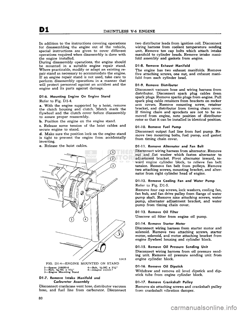
Dl-6.
Mounting Engine
On
Engine Stand
Refer
to Fig. Dl-4.
a.
With
the
engine
supported by a hoist, remove
the clutch housing and clutch. Match
mark
the flywheel and the clutch cover before disassembly to assure proper reassembly.
b. Position the
engine
on the
engine
stand.
c. Release
some
tension of the hoist cables and secure
engine
to stand.
d.
Make sure the position lock on the
engine
stand
is tight to prevent the
engine
from accidentally
inverting.
e.
Release the hoist cables.
FIG.
D1
-4—ENGINE
MOUNTED
ON
STAND
1—
Spacer
J-8690-6
A—Bolt,
i/2-NC
x 3i/2"
2—
Bolt,
3/a-NC
x 4*/2" 5—Adapter 21316-J 3—
Engine
Mounting Stand
Dl-7.
Remove Intake Manifold
and
Carburetor Assembly
Disconnect crankcase vent
hose,
distributor vacuum
hose,
and fuel line from carburetor. Disconnect two distributor leads from ignition coil. Disconnect
wiring
harness from coolant temperature sending
unit.
Remove ten cap
bolts
which attach intake
manifold to cylinder heads. Remove intake mani
fold assembly and gaskets from
engine.
Dl-8. Remove Exhaust Manifold
The
engine
has two exhaust manifolds. Remove five attaching screws, one nut, and exhaust mani
fold from each cylinder head.
Dl-9.
Remove Distributor
Disconnect vacuum
hose
and wiring harness from
distributor.
Disconnect spark plug cables from
spark
plugs. Remove sparks plugs from
engine.
Pull
spark
plug cable retainers from brackets on rocker
arm
covers. Remove mounting screw, retainer
bracket,
and distributor from timing chain cover.
If
timing chain and sprockets are not to be re
moved from
engine,
note
position of distributor
rotor so that it can be installed in identical position.
Dl-10. Remove
Fuel Pump
Disconnect output fuel line from fuel pump. Re
move
two mounting bolts, fuel pump, and gasket
from
timing chain cover.
Dl-11.
Remove Alternator
and Fan
Belt
Disconnect wiring harness from alternator. Remove nut and flat washer which fasten alternator to
adjustment bracket. Pivot alternator
inward,
to
ward
engine
cylinder block, to relieve fan belt
tension. Remove fan belt from pulleys. Remove
two attaching screws, mounting bracket, and alter nator from right cylinder head of
engine.
Dl-12.
Remove Cooling
Fan and
Water Pump
Refer
to Fig. Dl-5.
Remove four cap screws, lock washers, cooling fan,
fan
hub, and fan drive pulley from flange of water
pump shaft. Remove nine attaching screws, water
pump, alternator adjustment bracket, and water pump from timing chain cover.
Dl-13.
Remove
Oil
Filter
Unscrew
oil filter from
engine
oil pump.
Dl-14.
Remove Starter Motor
Disconnect wiring harness from starter motor and
solenoid. Remove two attaching screws, starter motor, solenoid, and motor attaching bracket from
engine
flywheel housing and cylinder block.
Dl-15.
Remove
Oil
Pressure Sending Unit
Disconnect wiring harness from oil pressure send
ing unit. Remove oil pressure sending unit from
engine
cylinder block.
Dl-16.
Remove
Oil
Dipstick
Withdraw
and remove oil level dipstick and dip
stick
tube
from
engine
cylinder block.
Dl-17.
Remove Crankshaft Pulley
Remove six attaching screws and crankshaft pulley
from
crankshaft vibration damper. 80
Page 81 of 376
'Jeep'
UNIVERSAL
SERIES
SERVICE
MANUAL
Dl
13296
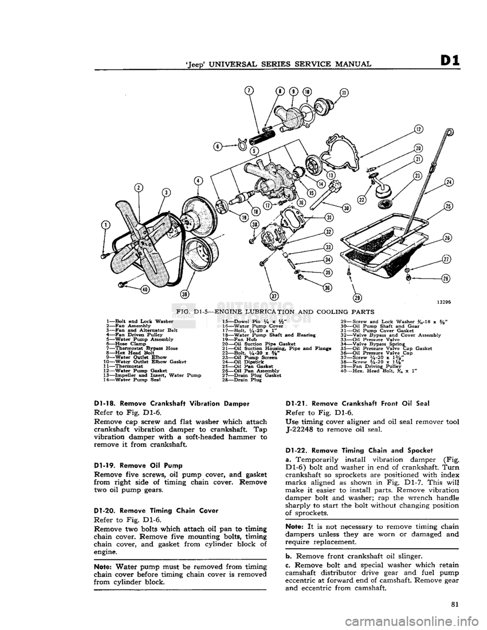
FIG.
Dl-5—ENGINE
LUBRICATION
AND
COOLING
PARTS
1— Bolt and
Lock
Washer
2—
Fan
Assembly
3—
Fan
and Alternator Belt
4—
Fan
Driven Pulley 5— Water Pump Assembly
6—
Hose
Clamp 7— Thermostat Bypass
Hose
8—Hex
Head Bolt
9— Water Outlet Elbow
10— Water Outlet Elbow Gasket
11— Thermostat
12— Water Pump Gasket
13— Impeller and Insert, Water Pump
14— Water Pump Seal 15— Dowel Pin % x Vfc"
16— Water Pump Cover
17— Bolt,
1/4-20
x 1"
18— Water Pump Shaft and Bearing
19—
Fan
Hub
20—
-Oil
Suction Pipe Gasket
21—
Oil
Suction Housing, Pipe and Flange
22— Bolt,
y4-20
x s/8"
23—
Oil
Pump Screen
24—
Oil
Dipstick
25—
Oil
Pan Gasket
26—
Oil
Pan Assembly
27—
Drain
Plug Gasket
28—
Drain
Plug 29— Screw and
Lock
Washer #6-18 x %
30—
Oil
Pump Shaft and Gear
31—
Oil
Pump Cover Gasket
32— Valve Bypass and Cover Assembly
33—
Oil
Pressure Valve 34— Valve Bypass Spring
35—
Oil
Pressure Valve Cap Gasket
36—
Oil
Pressure Valve Cap
37— Screw V4-20 x lVg"
38— Screw 1/4-20 x 1W' 39—
Fan
Driving Pulley
40— Hex. Head Bolt, x 1"
Dl-13.
Remove
Crankshaft
Vibration Damper
Refer
to Fig. Dl-6.
Remove cap screw and flat washer which attach
crankshaft
vibration damper to crankshaft. Tap
vibration
damper with a soft-headed hammer to remove it from crankshaft.
Dl-19.
Remove Oil Pump
Remove five screws, oil pump cover, and gasket
from
right side of timing chain cover. Remove
two oil pump gears.
D1-20.
Remove Timing Chain Cover
Refer
to Fig. Dl-6. Remove two
bolts
which attach oil pan to timing
chain
cover. Remove five mounting bolts, timing
chain
cover, and gasket from cylinder block of
engine.
Note:
Water pump must be removed from timing
chain
cover before timing chain cover is removed
from
cylinder block.
Dl-21.
Remove Crankshaft Front
Oil
Seal
Refer
to Fig. Dl-6.
Use timing cover aligner and oil seal remover
tool
J-22248 to remove oil seal.
Dl-22.
Remove Timing Chain
and
Spocket
a.
Temporarily install vibration damper (Fig.
Dl-6)
bolt and washer in end of crankshaft.
Turn
crankshaft
so sprockets are positioned with index
marks
aligned as shown in Fig. Dl-7.
This
will
make it easier to install parts. Remove vibration
damper bolt and washer; rap the wrench handle
sharply
to start the bolt without changing position
of sprockets.
Note:
It is not necessary to remove timing chain
dampers unless they are worn or damaged and
require
replacement.
b. Remove front crankshaft oil slinger.
c. Remove bolt and special washer which retain
camshaft distributor drive gear and fuel pump
eccentric at forward end of camshaft. Remove gear
and
eccentric from camshaft. 81
Page 102 of 376
![JEEP CJ 1953 User Guide
Dl
DAUNTLESS
V-6
ENGINE
FIG.
Dl-41—WATER
PUMP
AND
TIMING CHAIN COVER BOLT LOCATION
Cover
Bolts
alternately and evenly 8 to 12 lb-ft. [1,10 a 1,66
kg-m.].
Dl-88.
Install
Cranksh JEEP CJ 1953 User Guide
Dl
DAUNTLESS
V-6
ENGINE
FIG.
Dl-41—WATER
PUMP
AND
TIMING CHAIN COVER BOLT LOCATION
Cover
Bolts
alternately and evenly 8 to 12 lb-ft. [1,10 a 1,66
kg-m.].
Dl-88.
Install
Cranksh](/img/16/57040/w960_57040-101.png)
Dl
DAUNTLESS
V-6
ENGINE
FIG.
Dl-41—WATER
PUMP
AND
TIMING CHAIN COVER BOLT LOCATION
Cover
Bolts
alternately and evenly 8 to 12 lb-ft. [1,10 a 1,66
kg-m.].
Dl-88.
Install
Crankshaft
Vibration
Damper
a.
Lubricate
the vibration damper hub
before
in
stallation to prevent
damage
to the crankshaft
front oil seal during installation and when the
engine
is first started.
b.
Install
the vibration damper on the crankshaft.
Secure it with its attaching flat washer and screw.
Torque
the screw to a minimum of 140 lb-ft.
[19,35
kg-m.].
Dl-89.
Install
Crankshaft Pulley
Secure the crankshaft pulley to the crankshaft
vibration
damper with six screws. Torque screws 18 to 25 lb-ft. [2,5 a 3,4 kg-m.].
Dl-90.
Install
Oil
Level
Dipstick
Insert
oil level dipstick
into
the dipstick tube.
Dl-91.
Install
Oil
Pressure Sending Unit
Install
oil pressure sending unit in cylinder block.
Connect electrical wiring harness to unit.
Dl-92.
Install Starting Motor
Secure starting motor and
solenoid
assembly to
the flywheel housing and cylinder block with two attaching screws. Torque screw, which attaches this
assembly to the flywheel housing, 30 to 40 lb-ft. [4,1 a 5,5 kg-m.]. Torque screw, which attaches
bracket
to cylinder block, 10 to 12 lb-ft. [1,4 a 1,7 kg-m.].
Dl-93.
Install
Oil
Filter
Install
a new oil filter
element
at oil filter nipple,
at
left
side
of timing chain cover. Torque 10 to 15 lb-ft. [1,38 a 2,07 kg-m.].
D1-94. Install Water Pump
Be
certain that mating surfaces of the water pump
and
timing chain cover are clean.
Install
a new
gasket
on the pump flange. Secure the pump and
alternator adjustment bracket to the cover with
nine attaching bolts. Torque
bolts
6 to 8 lb-ft. [0,83 a 1,10 kg-m.]. Refer to Fig. Dl-41.
D1-9S.
Install
Cooling Fan
Secure the cooling fan, fan hub, and fan drive
pulley to the water pump shaft
flange
with four
attaching screws. Torque screws 17 to 23 lb-ft. [2,35 a 3,18 kg-m.].
Dl-96.
Install
Alternator
and Fan
Belt
Mount the alternator and bracket assembly on
right
cylinder head with two attaching screws.
Torque
screws 30 to 40 lb-ft. [4,1 a 5,5 kg-m.].
Fasten
the alternator
loosely
to its adjustment
bracket
with attaching flat washer and nut.
Install
the fan
belt
on its pulleys. Pivot the alternator
outward,
away from cylinder block, to apply fan
belt
tension. Adjust fan
belt
tension to 80 lb. [36,2 kg.];
tighten
alternator-to-adjustment bracket
nut to secure adjustment
setting.
Connect wiring
harness to alternator.
Dl-97.
Install
Fuel Pump
Install
two mounting
bolts
and new
gasket
on
flange
of fuel pump. Secure pump to timing chain cover with screws; torque screws 17 to 23 lb-ft. [2,35 a 3,8 kg-m.]. Connect
output
fuel line to
pump.
Dl-98.
Install Exhaust Manifold
Secure each of two exhaust manifolds to corre
sponding cylinder head with five attaching screws,
and
one nut. Torque screws and nut 15 to 20 lb-ft. [2,07 a 2,8 kg-m.]. See Fig. Dl-42.
Dl-99.
Install Distributor
Insert
distributor drive gear
into
distributor mount-
FIG.
Dl-42—EXHAUST
MANIFOLD INSTALLATION
1—Torque
Bolts—15
to 20
lb-ft.
[2,07 a 2,8
kg-m.]
102
Page 104 of 376
Dl
DAUNTLESS
V-6
ENGINE
e.
Connect electrical wiring harness to coolant
temperature sending unit. Connect two distributor leads to ignition coil. Connect fuel line
between
fuel pump and carburetor, vacuum
hose
between
distributor and carburetor, and crankcase vent
hose
to intake manifold
below
rear
of carburetor.
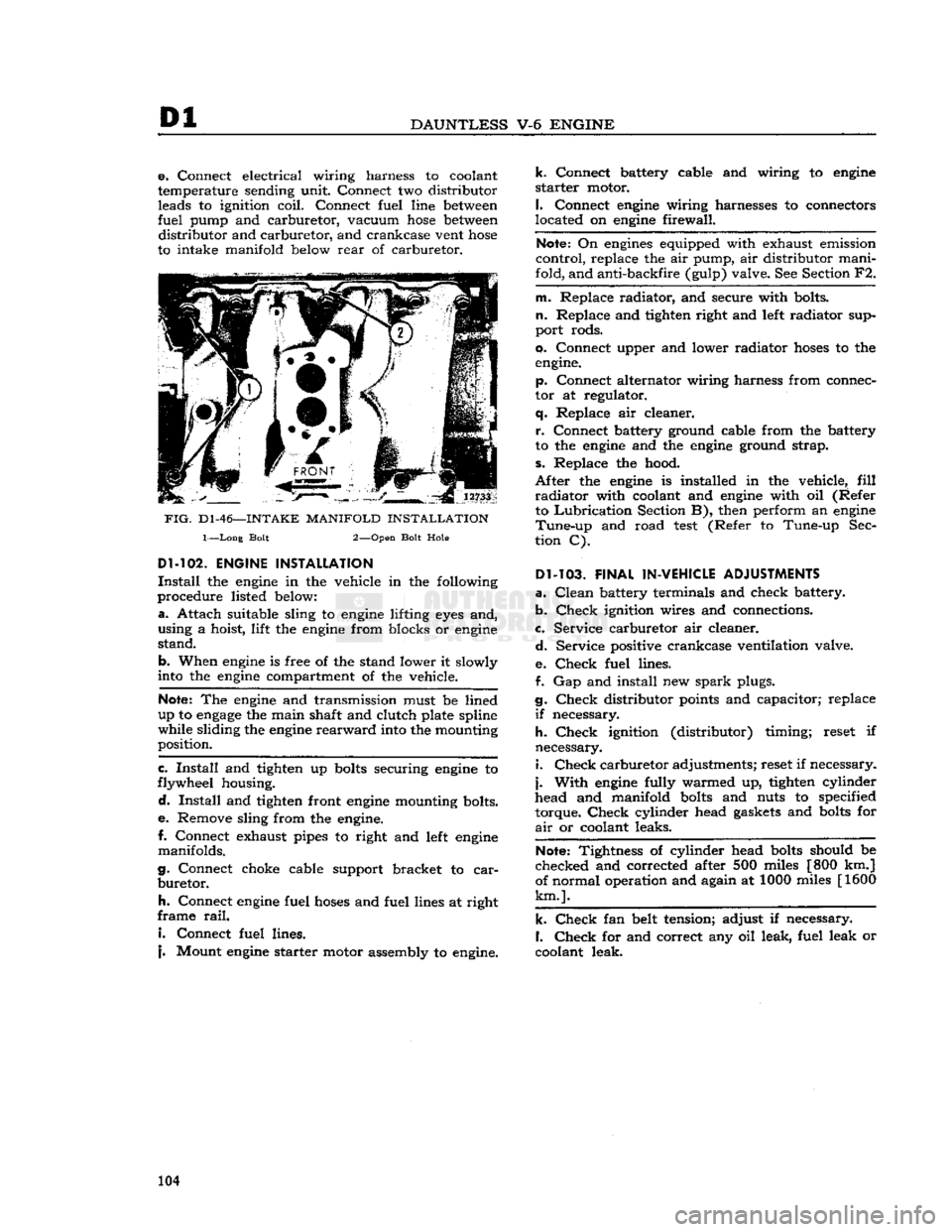
FIG.
D1-46—-INTAKE
MANIFOLD
INSTALLATION
1—Long Bolt 2—Open Bolt Hole
Dl-102.
ENGINE INSTALLATION
Install
the
engine
in the vehicle in the following
procedure listed
below:
a.
Attach suitable sling to
engine
lifting
eyes
and,
using a hoist, lift the
engine
from blocks or
engine
stand.
b. When
engine
is free of the stand lower it slowly
into
the
engine
compartment of the vehicle.
Note:
The
engine
and transmission must be lined
up to
engage
the main shaft and clutch plate spline
while sliding the
engine
rearward
into
the mounting
position.
c.
Install
and tighten up
bolts
securing
engine
to
flywheel housing.
d.
Install
and tighten front
engine
mounting bolts.
e.
Remove sling from the
engine.
I.
Connect exhaust pipes to right and
left
engine
manifolds.
g. Connect choke cable support bracket to
car
buretor.
h.
Connect
engine
fuel
hoses
and fuel lines at right
frame
rail.
I.
Connect fuel lines.
j.
Mount
engine
starter motor assembly to
engine.
k.
Connect battery cable and wiring to
engine
starter
motor.
I.
Connect
engine
wiring harnesses to connectors
located on
engine
firewall.
Note:
On
engines
equipped with exhaust emission
control, replace the air pump, air distributor mani
fold, and anti-backfire (gulp) valve. See Section F2.
m. Replace radiator, and secure with bolts,
n.
Replace and tighten right and
left
radiator sup
port rods.
0. Connect upper and lower radiator
hoses
to the
engine.
p. Connect alternator wiring harness from connec
tor at regulator,
q.
Replace air cleaner.
r.
Connect battery ground cable from the battery
to the
engine
and the
engine
ground strap,
s.
Replace the hood.
After
the
engine
is installed in the vehicle,
fill
radiator
with coolant and
engine
with oil (Refer to
Lubrication
Section B), then perform an
engine
Tune-up
and road
test
(Refer to Tune-up Sec
tion C).
Dl-103.
FINAL IN-VEHICLE ADJUSTMENTS
a.
Clean
battery terminals and check battery.
b.
Check
ignition wires and connections.
c. Service carburetor air cleaner.
d.
Service positive crankcase ventilation valve.
e.
Check
fuel lines.
f. Gap and install new
spark
plugs.
g.
Check
distributor
points
and capacitor; replace
if
necessary.
h.
Check
ignition (distributor) timing; reset if
necessary. 1.
Check
carburetor adjustments; reset if necessary,
j.
With
engine
fully warmed up, tighten cylinder
head and manifold
bolts
and nuts to specified
torque.
Check
cylinder head
gaskets
and
bolts
for
air
or coolant leaks.
Note:
Tightness of cylinder head
bolts
should be
checked and corrected after 500 miles [800 km.]
of normal operation and again at 1000 miles [1600
km.].
k.
Check
fan belt tension; adjust if necessary.
I.
Check
for and correct any oil leak, fuel leak or
coolant leak. 104
Page 105 of 376
'Jeep'
UNIVERSAL
SERIES SERVICE
MANUAL
Dl
Dl-104.
SERVICE
DIAGNOSIS
Poor Fuel Economy
Ignition Timing Late or Spark Advance Inoperative
Carburetor
Float Setting Too High
Accelerator Pump Improperly Adjusted
Fuel
Pump Pressure High
Fuel
Line
Leakage
Fuel
Pump Diaphragm Leakage
Cylinder
Compression Low
Valves Do Not Seat Properly
Spark
Plugs
Defective
Spark
Plug Cables
Defective
Ignition
Coil
or Capacitor
Defective
Carburetor
Air Cleaner Dirty
Brakes
Drag
Wheel Alignment Incorrect
Tire
Pressure Incorrect Odometer Inaccurate
Fuel
Tank
Cap Clogged or
Defective
Muffler or Exhaust Pipe Clogged or Bent
Lack
of
Power
Cylinder
Compression Low
Ingitdon Timing Late
Carburetor
or
Fuel
Pump Clogged or
Defective
Fuel
Lines Clogged
Air
Cleaner Restricted
Engine Temperature High Valves Do Not Seat Property
Valve
Timing Late Intake Manifold or Cylinder Head
Gasket Leaks
Muffler or Exhaust Pipe Clogged or Bent
Spark
Plugs Dirty or
Defective
Breaker
Point Gap Incorrect
Breaker
Points
Defective
Ignition
Coil
or Capacitor
Defective
Electrical
Connection Loose
Broken
Valve Spring
Broken
Piston Ring or Piston
Cylinder
Head Gasket
Defective
Distributor Cap Cracked
Low
Compression
Valves Not Seating Properly Piston Rings Seal Poorly
Valve
Spring Weak or Broken
Cylinder
Scored or Worn
Piston Clearance Too Great
Cylinder
Head Gasket Leaks
Burned
Valves and
Seats
Valves Stick or Are Too Loose in Guides
Valve
Timing Incorrect
Valve
Head and Seat Have Excessive Carbon
Engine Overheats
Valve
Spring Weak or Broken
Valve
Lifter Seized or Collapsed
Exhaust
System Clogged
Valves Sticking
Valve
Stem Warped
Valve
Stem Carbonized or Scored
Valve
Stem Clearance Insufficient in Guide
Valve
Spring Weak or Broken
Valve
Spring Distorted
Oil
Contaminated
Overheating
Cooling System Inoperative
Thermostat Inoperative Ignition Timing Incorrect
Valve
Timing Incorrect
Carbon
Accumulation Excessive
Fan
Belt Loose
Muffler or Exhaust Pipe Clogged or Bent
Oil
System Failure
Piston Rings Worn or Scored
Popping,
Spitting,
Detonation
Ignition Timing Incorrect
Carburetion
Improper
Carbon
Deposit
in Combustion
Chambers Excessive
Valves Not Seating Properly
Valve
Spring Broken
Spark
Plug Electrodes Burned
Water or Dirt in
Fuel
Fuel
Line
Clogged
Valve
Timing Incorrect
Excessive
Oil
Consumption
Piston Rings Stuck in Grooves, Weak,
Worn,
Broken, or Incorrectly Fitted
Crankshaft
Main Bearings or
Connecting Rod Bearings Have
Excessive Clearance
Gaskets or Oil Seals
Leak
Cylinder
Bores Worn, Scored,
Out-of-Round or Tapered
Pistons Have Too Great Clearance to Cylinder Bores
Connecting Rods Misaligned High Road Speed
High Temperature
Crankcase
Ventilation System Inoperative
Bearing Failure
Crankshaft
Bearing Journal Rough or Out-of-Round
Oil
Level Low
Oil
Leakage
Oil
Dirty
Oil
Pressure Low or Lacking
(Oil
Pump Failure)
Drilled
Passages
in Crankshaft or
Crankcase
Clogged
Oil
Screen Dirty
Connecting Rod Bent 105
Page 143 of 376
'Jeep'
UNIVERSAL SERIES SERVICE
MANUAL
Fl
EXHHUST
EMISSION
CONTROL
SYSTEM
Contents
HURRICANE
F4-134
ENGINE
SUBJECT
PAR.
GENERAL
Fl-1
AIR
PUMP
Fl-2
PUMP
AIR
FILTER
Fl-3
AIR
DELIVERY
MANIFOLD
Fl-4
AIR INJECTION TUBES.
Fl-5
ANTI-BACKFIRE
DIVERTER
VALVE.
.Fl-6
ENGINE
COMPONENTS
. .Fl-7
Carburetor
. .Fl-8
Distributor
........
.Fl-9
Exhaust
Manifold Fl-10
MAINTENANCE
Fl-11
Carburetor
Fl-12,
Fl-13
Distributor
Fl-14
Anti-Backfire
Diverter
Valve.
.........
.Fl-15
Check
Valve Fl-16
Fl-1. GENERAL—F4-134
Engine
The
Hurricane
F4-134
engine
Exhaust
Emission
Control
System consists of a belt driven air pump
which
directs compressed air through connecting
hoses
to a steel distribution manifold into stainless steel injection
tubes
in the exhaust port adjacent
to each exhaust valve stem.
This
air with its normal
oxygen
content, reacts with the hot but incom
pletely burned exhaust
gases
and permits further combustion in the exhaust port or manifold.
Fl-2. AIR
PUMP
The
air injection pump is a positive displacement
vane type which is permanently lubricated and
requires
no periodic maintenance.
The
pump contains an integral relief valve which controls the air supplied to the
engine
exhaust ports
during
high speed operation to limit maximum ex
haust system temperatures.
Fl-3. PUMP
AIR
FILTER
The
air filter attached to the pump is a replaceable
element type constructed of conventional pleated
paper
with steel end plates.
The
filter should be replaced every
12,000
miles
[19,200
km.] under normal conditions or sooner
under
adverse weather or driving conditions.
Fl-4.
AIR
DELIVERY
MANIFOLD
The
air delivery manifold, constructed of cold
rolled
steel with a zinc plating, distributes the air
from
the pump to each of the air delivery
tubes
in
a uniform manner.
A
check valve is attached to the air delivery
SUBJECT
PAR.
Air
Pump Fl-17
Carburetor
Air Cleaner Fl-18
REMOVAL PROCEDURES
.Fl-19
Air
Pump
Fl-20
Anti-Backfire
Diverter Valve Fl-21
Air
Distribution Manifold,
And
Air Injection Tubes
Fl-22
REQUIRED
EQUIPMENT
.Fl-23
REPLACEMENT
PARTS
Fl-24
WARRANTY
Fl-25
DIAGNOSIS
GUIDE
Fl-26
MAINTENANCE CHART
Fl-27
CARBURETOR SPECIFICATIONS
Fl-28
DISTRIBUTOR SPECIFICATIONS
Fl-29
SPARK PLUG
GAP
.Fl-30
manifold.
Its function is to prevent the reverse flow
of exhaust
gases
to the pump should the pump
drive
fail.
This
reverse flow would damage the air
pump and connecting
hose.
Fl-5.
AIR
INJECTION
TUBES
The
air injection
tubes
of stainless steel are inserted
into machined
bosses
of the exhaust manifold. The
tubes
project into the exhaust ports directing air
into the vicinity of the exhaust valve stem.
Fl-6.
ANTI-BACKFIRE DIVERTER VALVE
The
anti-backfire diverter valve prevents
engine
backfire
by briefly interrupting the air being in
jected into the exhaust manifold during periods of deceleration (rapid throttle closure).
Fl-7.
ENGINE
COMPONENTS
The
following items
vary
in design or specifications
from
those
on vehicles not equipped with the Ex
haust Emission
Control
System.
Fl-8.
Carburetor
A
carburetor with a specific flow characteristic is used for exhaust emission control.
A
carburetor dashpot is provided to control the throttle closing speed.
Fl-t.
Distributor
The
ignition distributor used with the exhaust emission system requires a different advance curve
from
that used on the F4-134
engine
prior
to the
introduction of exhaust emission systems. 143
Page 145 of 376
'Jeep'
UNIVERSAL
SERIES SERVICE
MANUAL
Fl
b. Connect tachometer to
engine.
c.
Warm
up
engine
and stabilize temperatures.
d.
Adjust
engine
idle to
speed
desired, using throt
tle idle
speed
adjusting screw.
e.
Carburetors without Idle
Limiter
Cap turn idle mixture screws out (counterclockwise) until a
loss
of
engine
speed
is indicated; then, slowly turn mix
ture screw in (clockwise-leaner) until maximum
speed
(RPM) is reached. Continue turning in (clockwise) until
speed
begins
to drop; turn mixture
adjustment back out (counterclockwise-richer) un
til
maximum
speed
is just regained at a "lean as
possible" mixture adjustment.
Fl-14.
Distributor
Check
the distributor number for proper appli
cation.
Check
the distributor cam dwell angle and
point condition and adjust to specifications or re place as required. (Specifications listed at the end
of this section)
Check
ignition timing and set at
0°
or
TDC.
Fl-15.
Anti-iackfire
Diverter Valve
The
anti-backfire valve remains closed
except
when
the throttle is closed rapidly from an
open
position.
To
check the valve for proper operation, accelerate
the
engine
in neutral, allowing the throttle to
close
rapidly.
The valve is operating satisfactorily when
no exhaust system backfire occurs. A further check
to determine whether the valve is functioning can be made by removing from the anti-backfire valve
the large
hose
Which
connects to the check valve.
Accelerate the
engine
to allow the throttle to
close
rapidly.
The valve is operating satisfactorily if a
momentary interruption of rushing air is audible.
Fl-16.
Check Valve
The
check valve prevents the reverse flow of ex
haust
gases
to the pump in the
event
the pump
should, for any reason,
become
inoperative or should exhaust pressure ever
exceed
pump pressure.
To
check this valve for proper operation, remove the air supply
hose
from the pump at the
distri
bution manifold.
With
the
engine
running, listen for exhaust leakage at the check valve which is
connected to the distribution manifold.
Fl-17.
Air
Pump
Check
for proper drive belt tension with belt tension
gauge
W-283. The belt strand tension should be
50-60
pounds on a belt with previous service, meas
ured
on the
longest
accessible span
between
two pulleys. When installing a new belt, adjust the
tension to
60-80
pounds tension. DO NOT PRY
ON
THE DIE
CAST
PUMP
HOUSING.
To
check the pump for proper operation, remove the air
outlet
hose
at the pump.
With
the
engine
running,
air discharge should be
felt
at the pump
outlet
opening. The pump
outlet
air pressure, as determined by the relief valve, is preset and is not
adjustable.
The
air pump
rear
cover assembly, housing the pressed in inlet and discharge tubes, and the pres
sure relief valve are the only pump
components
recommended for service replacement. These parts
are
to be replaced only when damaged as a result
of handling or in the
event
the relief valve was
tampered with.
Fl-18.
Carburetor
Air
Cleaner
Every
6000
miles
[9,600
km.] clean the inside
sur
face at the sump and
refill
to indicated oil level with
SAE
40 or 50
engine
oil
above
32 F; SAE 20
below
32 F. Wash filter
element
in kerosene and
drain.
Reassemble the air cleaner.
More
frequent cleaning and replacement is advis able when the car is operated in dusty areas or on
unpaved roads. Accumulated dirt restricts air flow,
reducing fuel
economy
and performance.
Fl-19.
REMOVAL
PROCEDURES
The
following paragraphs
give
the procedures for removing the major units of the Exhaust Emission
Control
System and the required equipment
needed.
Fl-20.
Air
Pump
Loosen
the air pump adjusting strap to facilitate
drive
belt removal. Remove the air pump air dis
charge hose(s) and air filter attachment. Separate
the air pump from its mounting bracket. At time of installation, torque tighten the air pump mounting
bolts
to
30-40
lbs-ft. [4,15 a 5,53 kg-m.]. Adjust
the belt strand tension to
50-60
pounds on a belt
with previous service and
60-80
pounds on a new
belt.
Fl-21.
Anti-Backfire
Diverter Valve
The
anti-backfire diverter valve removal requires disconnecting the
hoses
and bracket to
engine
at
taching screws.
Fl-22.
Air
Distribution
Manifold
and
Injection Tubes
In
order to remove the air distribution manifold
without bending the tubing, which could result in
fractures
or leakage, it is necessary to remove the
exhaust manifold as an assembly from the
engine.
After
the exhaust manifold assembly is removed
from
the
engine,
place the manifold in a vise and
loosen
the air distribution manifold
tube
retaining nuts at each cylinder exhaust port. Tap the injec
tion
tubes
lightly to allow the air distribution mani
fold to be pulled away partially from the exhaust manifold. The stainless steel injection
tubes
in the
exhaust manifold may have
become
partially fused
to the air distribution manifold and, therefore, may
require
application of heat to the joint in order to
separate. While applying heat to the joint, rotate
the injection
tubes
with pliers being careful not to
damage the
tubes
by applying excessive force.
At
time of installation, the air injection
tubes
must
be positioned into the exhaust manifold prior to
placing the exhaust manifold assembly on the en gine.
Note:
Two different length injection
tubes
are used.
The
shorter length injection
tubes
must be inserted into cylinders 1 and 4. 145
Page 146 of 376
Fl
EXHAUST
EMISSION CONTROL SYSTEMS The
air distribution manifold should be installed
after the exhaust manifold assembly is torqued
to the cylinder head. The recommended procedure
for exhaust manifold assembly installation is as follows:
Clean
the mating surface of both the
manifold and cylinder head.
Install
the exhaust manifold to the cylinder head using a new gasket.
Tighten
the manifold to cylinder head, attaching
bolts
down evenly.
Finish
torque tightening to 29
to 35 ft. lbs. [3,4 a 4,8 kg-m.].
Fl-23.
REQUIRED
EQUIPMENT
Each
station licensed to perform repair and main
tenance on the Exhaust Emission Control System
must be equipped with that equipment necessary
for major
engine
tune-up analysis which shall in clude at least the following or equivalent.
Ignition Analyzer Oscilloscope
Ammeter
Ohmmeter
Voltmeter Tachometer
2 Vacuum Gages
Pressure
Gage (0-10 psi.)
Cam
Angle Dwell Meter Ignition Timing
Light
Engine
Exhaust Combustion Analyzer Compression Tester
Fl-24.
REPLACEMENT
PARTS
Parts
necessary to repair and/or maintain the
Exhaust
Emission Control System are available through any Jeep
SALES CORPORATION
ware
house.
Fl-25.
WARRANTY
All
parts of the Exhaust Emission Control System
are
covered by the Manufacturer's Warranty as stated in the Warranty Service and 'Jeep' Quality
Maintenance Plan booklet.
Fl-26.
EXHAUST EMISSION CONTROL
SYSTEM
DIAGNOSIS GUIDE
Pump Noisy
Hoses Touching Other Parts of Engine or Body (Hood).
Note:
The air pump is not completely noiseless.
Under
normal conditions, pump
noise
rises in pitch as
engine
speed
increases. It is also desirable to
allow for normal break-in wear of the pump prior
to replacement for excessive noise.
Pump Seized
Replace
pump.
Leak
In
Hose
Check
for leaks; using
soap
and water — tighten
clamps or replace
hoses.
Pump
Inoperative
Loose Belt — tighten belt — do not pry on housing.
Filter
Plugged — replace.
Exhaust Backfire
Check
for vacuum leaks — correct as necessary.
Check
air filter for excessive
restriction
— replace as necessary.
Check
anti-backfire valve — replace as necessary.
Induction System Backfire
Verify
engine
timing and distributor dwell.
Verify
accelerator pump charge. 146