torque JEEP CJ 1953 Service Manual
[x] Cancel search | Manufacturer: JEEP, Model Year: 1953, Model line: CJ, Model: JEEP CJ 1953Pages: 376, PDF Size: 19.96 MB
Page 6 of 376
GENERAL
DATA
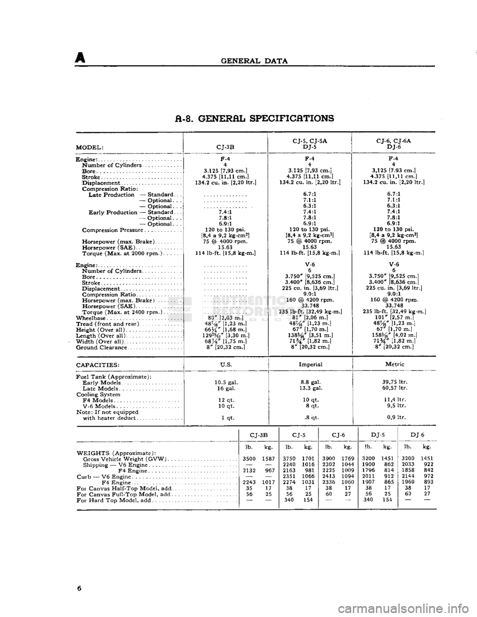
A-8. GENERAL SPECIFICATIONS
MODEL:
CJ-3B
CJ-5,
CJ-5A
DJ-5
CJ-6,
CJ-6A
DJ-6
Engine:.
Number
of
Cylinders
Bore.
.
Stroke.
Displacement
Compression
Ratio:
Late
Production —
Standard
—
Optional.
—
Optional.
Early
Production —
Standard
—
Optional.
—
Optional.
Compression
Pressure
Horsepower
(max.
Brake)
Horsepower
(SAE)
Torque
(Max. at 2000
rpm.).
. . .
Engine:
Number
of
Cylinders
Bore
Stroke
Displacement
Compression
Ratio
Horsepower
(max.
Brake).
Horsepower
(SAE)
Torque
(Max. at 2400
rpm.).
. . .
Wheelbase
Tread
(front and
rear)
,
Height
(Over
all)
Length
(Over
all).
Width
(Over
all)
Ground
Clearance
F-4
4
3.125 [7,93 cm.]
4.375 [11,11 cm.]
134.2 cu. in. [2,20 ltr.]
7.4:1 7.8:1
6.9:1
120 to 130 psi.
[8,4 a 9,2 kg-cm2] 75 <§ 4000 rpm.
15.63
114 lb-ft. [15,8 kg-m.]
80"
[2,03 m.]
487-'f6/' [1,23 m.|
6634" [1,68 m.j
129%"
[3,30 m.]
68%"
[1,75 m.] 8" [20,32 cm.]
F-4
4
3.125 [7,93 cm.]
4.375 [11,11 cm.]
134.2 cu. in. [2,20 ltr.]
6.7:1 7.1:1
6.3:1 7.4:1
7.8:1
6.9:1
120 to 130 psi.
[8,4 a 9,2 kg-cm2] 75 @ 4000 rpm. 15.63
114 lb-ft. [15,8 kg-m.]
V-6
6
3.750" [9,525 cm.]
3.400" [8,636 cm.]
225 cu.
in.
[3,69 ltr.] 9.0:1
160 @ 4200 rpm. 33.748
235 lb-ft. [32,49 kg-m.]
81"
[2,06 m.]
48K6"
[1,23 m.]
67"
[1,70 m.]
138%"
[3,51 m.]
71%"
[1,82 m.] 8" [20,32 cm.]
F-4
4
3,125 [7.93 cm.]
4.375 [11,11 cm.]
134.2 cu. in. [2,20 ltr.]
6.7:1 7.1:1
6.3:1 7.4:1
7.8:1
6.9:1
120 to 130 psi.
[8,4 a 9,2 kg-cm2] 75 @ 4000 rpm.
15.63
114 lb-ft. [15,8 kg-m.]
V-6
6
3.750" [9,525 cm.]
3.400" [8,636 cm.]
225 cu. in. [3,69 ltr.] 9.0:1
160 @, 4200 rpm. 33 748
235 lb-ft. [32,49 kg-m.]
101"
[2,57 m.]
48^6* ]1,23 m.]
67"
[1,70 m.]
1583/4" [4,02 m.]
71%"
[1,82 m.] 8" [20,32 cm.]
CAPACITIES:
U.S.
Imperial
Metric
Fuel
Tank
(Approximate):
Early
Models
Late
Models
Cooling
System
F4
Models
V-6
Models
Note: If not equipped
with
heater deduct 10.5 gal.
16 gal.
12 qt.
10 qt.
1 qt. 8.8 gal.
13.3 gal.
10 qt. 8 qt.
.8 qt. 39,75 ltr.
60,57 ltr.
11,4 ltr. 9,5 ltr.
0,9 ltr.
CJ-
3B
CJ-5
CJ-6
DJ-5
DJ
-6
lb. kg. lb.
kg. lb.
kg. lb.
kg. lb.
kg.
WEIGHTS
(Approximate):
Gross
Vehicle
Weight
(GVW).
3500
1587 3750 1701 3900 1769 3200 1451 3200 1451
Shipping
— V6
Engine
—
'—
2240 1016 2302 1044 1900 862 2033 922
F4
Engine
2132
967 2163
981 2225
1009 1796 814 1858 842
Curb
— V6
Engine
— —
2351 1066 2413 1094 2011 912 2144 972
F4
Engine
2243
1017 2274 1031
2336 1060 1907 865 1969 893
For
Canvas
Half-Top
Model, add 35
17 38
17 38
17 38
17 38 17
For
Canvas
Full-Top
Model, add 56
25 56 25 60 27 56 25 60 27
For
Hard
Top Model, add
~~
340
154 340 154 6
Page 12 of 376
B
LUBRICATION B-3.
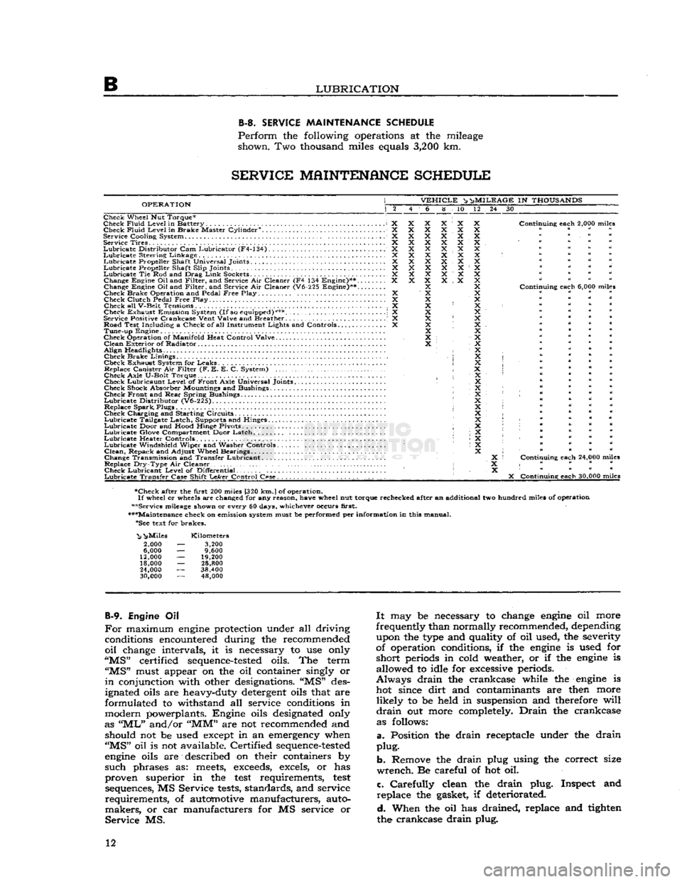
SERVICE
MAINTENANCE
SCHEDULE
Perform
the following operations at the mileage shown. Two thousand miles equals
3,200
km.
SERVICE
MAINTENANCE
SCHEDULE
OPERATION
VEHICLE
^ n>
MILEAGE
IN
THOUSANDS
6 8 10 12 24 30
Check Wheel Nut Torque*
Check
Fluid
Level
in Battery X Check
Fluid
Level
in Brake Master Cylinder0. X
Service
Cooling
System X Service Tires X
Lubricate
Distributor
Cam Lubricator (F4-134) X
Lubricate
Steering Linkage X
Lubricate
Propeller Shaft Universal Joints X
Lubricate
Propeller Shaft
Slip
Joints ; X
Lubricate
Tie Rod and Drag
Link
Sockets................................... X Change Engine
Oil
and
Filter,
and Service Air Cleaner (F4 134 Engine)** X
Change Engine Oil and
Filter,
and Service Air Cleaner (V6-225 Engine)**....
Check Brake Operation and Pedal
Free
Play X Check
Clutch
Pedal
Free
Play. .... X
Check all
V-Belt
Tensions X
Check Exhaust Emission System
(If
so equipped)*** \ X
Service Positive
Crankcase
Vent
Valve
and Breather . .' X
Road Test
Including
a Check of all Instrument
Lights
and Controls X Tune-up Engine
Check Operation of
Manifold
Heat
Control
Valve
Clean
Exterior of Radiator
Align
Headlights • Check Brake
Linings
,
Check Exhaust System for Leaks Replace Canister Air
Filter
(F. E. E. C. System)
Check
Axle
U-Bolt
Torque. Check Lubricaunt
Level
of Front
Axle
Universal Joints
Check Shock Absorber Mountings and Bushings Check Front and
Rear
Spring Bushings
Lubricate
Distributor
(V6-225).
Replace Spark, Plugs
Check Charging and Starting Circuits
Lubricate
Tailgate Latch, Supports and Hinges.
Lubricate
Door and
Hood
Hinge Pivots ;
Lubricate
Glove Compartment Door Latch
Lubricate
Heater Controls •
Lubricate
Windshield
Wiper and Washer Controls
Clean,
Repack and
Adjust
Wheel Bearings
Change Transmission and Transfer Lubricant. .
Replace
Dry-Type
Air Cleaner • Check Lubricant
Level
of
Differential
Lubricate
Transfer
Case
Shift
LeArer
Control
C«se.
. , . . . . . . . .
Continuing
each
2,000 miles
Continuing
each
6,000 miles
Continuing
each
24,000 miles
X
Continuing
each
30,000 miles
•Check after the
first
200 miles [320
km.
J
of operation.
If
wheel or wheels are changed for any
reason,
have
wheel nut torque rechecked after an additional two hundred miles of operation
••Service mileage shown or every 60 days, whichever occurs
first.
•••Maintenance check on emission system must be performed per
information
in this manual. "See text for brakes.
"Nj
^Miles
2,000
6,000
12,000
18,000
24,000
30,000
Kilometers
3,200
9,600
19,200
28,800
38,400 48,000
B-9.
Engine Oil
For
maximum
engine
protection under all driving conditions encountered during the recommended
oil
change intervals, it is necessary to use only
"MS"
certified
sequence-tested
oils. The term
"MS"
must appear on the oil container singly or
in
conjunction with other designations. "MS" des
ignated oils are heavy-duty detergent oils that are
formulated to withstand all service conditions in
modern powerplants. Engine oils designated only
as
"ML"
and/or
"MM"
are not recommended and should not be used except in an emergency when
"MS"
oil is not available. Certified
sequence-tested
engine
oils are described on their containers by
such
phrases as:
meets,
exceeds,
excels, or has
proven superior in the
test
requirements,
test
sequences, MS Service
tests,
standards, and service
requirements,
of automotive manufacturers, auto
makers,
or car manufacturers for MS service or
Service
MS.
It
may be necessary to change
engine
oil more
frequently than normally recommended, depending upon the type and quality of oil used, the severity
of operation conditions, if the
engine
is used for
short
periods in cold weather, or if the
engine
is allowed to idle for excessive periods.
Always
drain
the crankcase while the
engine
is hot since
dirt
and contaminants are then more
likely
to be held in suspension and therefore
will
drain
out more completely.
Drain
the crankcase as follows:
a.
Position the
drain
receptacle under the
drain
plug.
b.
Remove the
drain
plug using the correct size
wrench.
Be careful of hot oil.
c.
Carefully
clean the
drain
plug. Inspect and
replace
the gasket, if deteriorated.
d.
When the oil has drained, replace and tighten
the crankcase
drain
plug. 12
Page 16 of 376
B
LUBRICATION
Note:
Hard
shifting of the transmission gear in
cold weather is a positive indication that the
lubri
cant
is of the wrong viscosity or of poor quality
which
allows it to congeal.
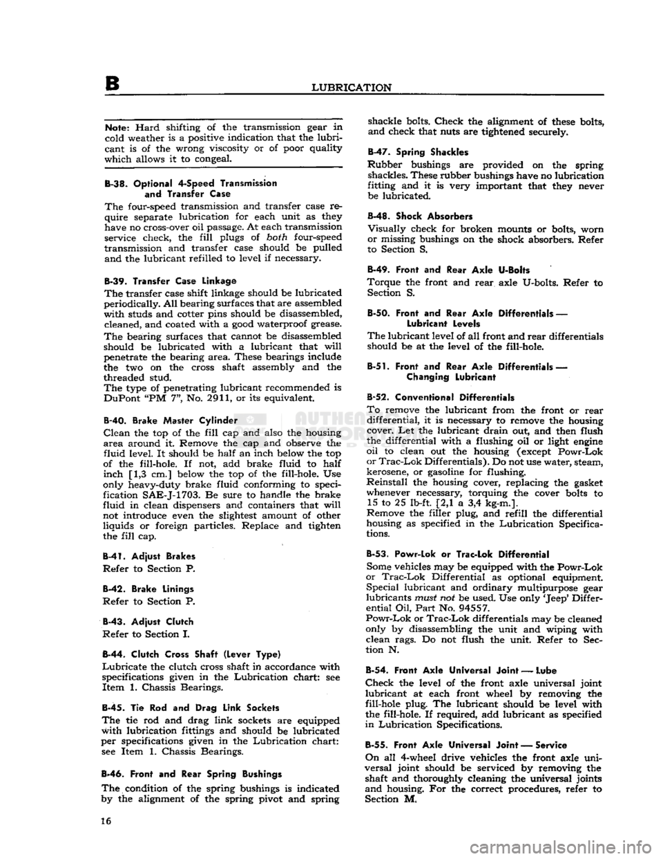
B-38.
Optional
4-Speed
Transmission
and
Transfer Case
The
four-speed transmission and transfer case re
quire
separate lubrication for each unit as
they
have no cross-over oil passage. At each transmission
service check, the
fill
plugs of
both
four-speed
transmission
and transfer case should be pulled
and
the lubricant refilled to level if necessary.
B-39.
Transfer
Case
Linkage
The
transfer case shift linkage should be lubricated
periodically.
All
bearing surfaces that are assembled
with
studs and cotter pins should be disassembled, cleaned, and coated with a
good
waterproof grease.
The
bearing surfaces that cannot be disassembled
should be lubricated with a lubricant that
will
penetrate the bearing
area.
These bearings include
the two on the cross shaft assembly and the
threaded stud.
The
type
of penetrating lubricant recommended is
DuPont
"PM 7", No. 2911, or its equivalent.
B-40.
Brake Master Cylinder
Clean
the top of the
fill
cap and also the housing
area
around it. Remove the cap and observe the
fluid
level. It should be
half
an inch
below
the top
of the fill-hole. If not, add brake fluid to
half
inch
[1,3 cm.]
below
the top of the fill-hole. Use
only heavy-duty brake fluid conforming to speci
fication
SAE-J-1703.
Be sure to handle the brake
fluid
in clean dispensers and containers that
will
not introduce even the
slightest
amount of other
liquids
or foreign particles. Replace and tighten
the
fill
cap.
B-41.
Adjust Brakes
Refer
to Section P.
B-42.
Brake Linings
Refer
to Section P.
B-43.
Adjust Clutch
Refer
to Section I.
B-44.
Clutch Cross Shaft (Lever Type)
Lubricate
the clutch cross shaft in accordance with
specifications given in the
Lubrication
chart: see
Item
1. Chassis Bearings.
B-45.
Tie Rod and Drag
Link
Sockets
The
tie rod and drag
link
sockets
are equipped
with
lubrication
fittings
and should be lubricated
per
specifications given in the
Lubrication
chart: see Item 1. Chassis Bearings.
B-46.
Front
and
Rear Spring
Bushings
The
condition of the spring bushings is indicated
by the alignment of the spring pivot and spring
shackle
bolts.
Check
the alignment of
these
bolts,
and
check that nuts are
tightened
securely.
B-47.
Spring
Shackles
Rubber
bushings are provided on the spring
shackles.
These rubber bushings have no lubrication
fitting and it is very important that
they
never be lubricated.
B-48.
Shock Absorbers
Visually
check for broken mounts or bolts, worn
or
missing bushings on the shock absorbers. Refer
to Section S.
B-49.
Front and
Rear
Axle
U-Bolts
Torque
the front and
rear
axle U-bolts. Refer to Section S.
B-50. Front
and
Rear
Axle
Differentials
—
Lubricant Levels
The
lubricant
level of all front and
rear
differentials should be at the level of the fill-hole.
B-51.
Front and
Rear
Axle
Differentials
—
Changing
Lubricant
B-52.
Conventional Differentials
To
remove the lubricant from the front or
rear
differential,
it is necessary to remove the housing cover. Let the lubricant
drain
out, and then flush
the differential with a flushing oil or light
engine
oil
to clean out the housing
(except
Powr-Lok
or
Trac-Lok
Differentials). Do not use water, steam,
kerosene, or
gasoline
for flushing.
Reinstall
the housing cover, replacing the gasket whenever necessary, torquing the cover
bolts
to 15 to 25 lb-ft. [2,1 a 3,4 kg-m.].
Remove the filler plug, and
refill
the differential
housing as specified in the
Lubrication
Specifica
tions.
B-53.
Powr-Lok
or
Trac-Lok Differential
Some vehicles may be equipped with the
Powr-Lok
or
Trac-Lok
Differential as optional equipment.
Special
lubricant and ordinary multipurpose gear
lubricants
must
not be used. Use only
'Jeep*
Differ
ential
Oil,
Part
No. 94557.
Powr-Lok
or
Trac-Lok
differentials may be cleaned
only by disassembling the unit and wiping with
clean
rags. Do not flush the unit. Refer to Sec
tion N.
B-54.
Front Axle Universal Joint
—
Lube
Check
the level of the front axle universal joint
lubricant
at each front wheel by removing the
fill-hole plug. The lubricant should be level with
the fill-hole. If required, add lubricant as specified
in
Lubrication
Specifications.
B-55.
Front
Axle
Universal
Joint
— Service
On
all 4-wheel drive vehicles the front axle
uni
versal
joint should be serviced by removing the shaft and thoroughly cleaning the universal joints
and
housing. For the correct procedures, refer to
Section M. 16
Page 19 of 376
Jeep*
UNIVERSAL SERIES SERVICE
MANUAL
c
TUNE-UP
Contents
SUBJECT
PAR.
GENERAL
C-l
TUNE-UP
.C-2
Air
Cleaner
C-21
Battery
. C-3
Carburetor
Adjustments
C-2 5
Coil
C-20
Crankcase
Ventilation C-6
Cylinder
Compression C-9
Cylinder
Head(s) .C-5
Dash
Pot Adjustments .C-26
Distributor
Service C-10
thru
C-13
Distributor
Resistance Test C-l6
Fan
Belt
C-2 7
Fuel
Lines
and Screens
C-2
2
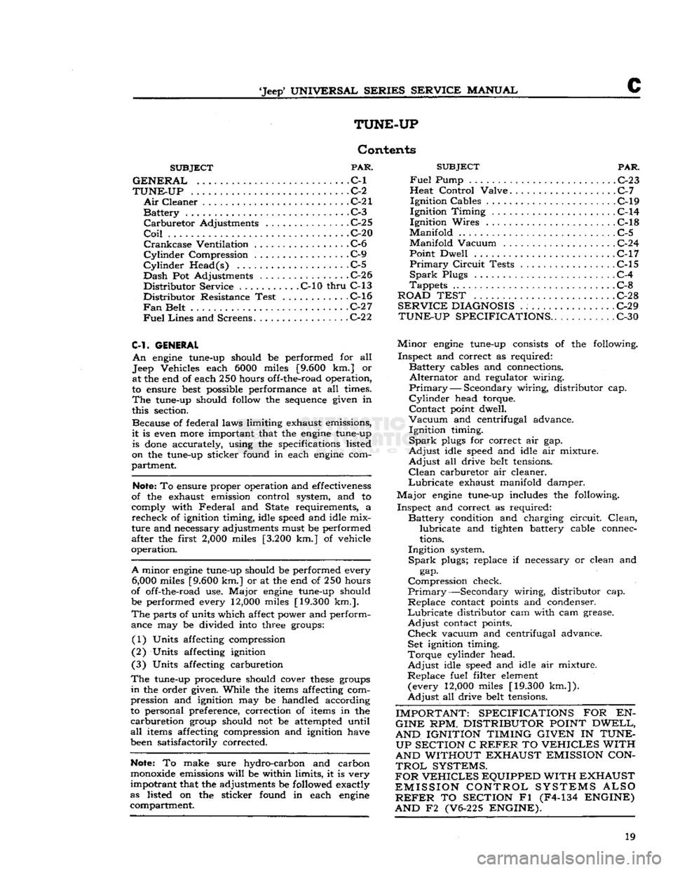
C-l.
GENERAL
An
engine tune-up should be performed for all
Jeep Vehicles each 6000 miles [9.600 km.] or at the end of each 250 hours off-the-road operation,
to ensure best possible performance at all times.
The
tune-up should follow the sequence given in
this section.
Because of federal laws limiting exhaust emissions,
it
is even more important that the engine tune-up is
done
accurately, using the specifications listed
on the tune-up sticker found in each engine com
partment.
Note;
To ensure proper operation and effectiveness
of the exhaust emission control system, and to
comply with
Federal
and State requirements, a
recheck
of ignition timing, idle speed and idle mix
ture
and necessary adjustments must be performed
after the first
2,000
miles [3.200 km.] of vehicle
operation.
A
minor engine tune-up should be performed every
6,000
miles [9.600 km.] or at the end of 250 hours
of off-the-road use.
Major
engine tune-up should
be performed every 12,000 miles [19.300 km.].
The
parts of units which affect power and perform
ance may be divided into three groups:
(1) Units affecting compression
(2) Units affecting ignition
(3) Units affecting carburetion
The
tune-up procedure should cover
these
groups
in
the order given. While the items affecting com
pression and ignition may be handled according
to personal preference, correction of items in the
carburetion
group should not be attempted until
all
items affecting compression and ignition have
been satisfactorily corrected.
Note:
To make sure hydro-carbon and carbon
monoxide emissions
will
be within limits, it is very
impotrant
that the adjustments be followed exactly
as listed on the sticker found in each engine compartment.
SUBJECT
PAR.
Fuel
Pump . . C-23
Heat
Control
Valve C-7
Ignition
Cables C-19
Ignition
Timing
. C-14
Ignition
Wires C-l8
Manifold
C-5
Manifold
Vacuum C-24
Point
Dwell C-17
Primary
Circuit
Tests
.................
C-15
Spark
Plugs C-4
Tappets
C-8
ROAD TEST C-2
8
SERVICE
DIAGNOSIS
. : C-29
TUNE-UP SPECIFICATIONS..
C-30
Minor
engine tune-up consists of the following.
Inspect
and correct as required:
Battery
cables and connections.
Alternator
and regulator wiring.
Primary
— Secondary wiring, distributor cap.
Cylinder
head torque.
Contact
point dwell.
Vacuum
and centrifugal advance.
Ignition
timing.
Spark
plugs for correct air gap.
Adjust
idle speed and idle air mixture.
Adjust
all drive belt tensions.
Clean
carburetor air cleaner.
Lubricate
exhaust manifold damper.
Major
engine tune-up includes the following.
Inspect
and correct as required:
Battery
condition and charging
circuit.
Clean,
lubricate
and tighten battery cable connec
tions.
Ingition
system.
Spark
plugs; replace if necessary or clean and gap.
Compression
check.
Primary—Secondary
wiring, distributor cap.
Replace
contact points and condenser.
Lubricate
distributor cam with cam grease.
Adjust
contact points.
Check
vacuum and centrifugal advance. Set ignition timing.
Torque
cylinder head.
Adjust
idle speed and idle air mixture.
Replace
fuel filter element (every 12,000 miles [19.300
km.]).
Adjust
all drive belt tensions.
IMPORTANT: SPECIFICATIONS
FOR EN-
GINE
RPM.
DISTRIBUTOR POINT DWELL,
AND IGNITION TIMING GIVEN
IN
TUNE- UP SECTION
C
REFER
TO
VEHICLES
WITH
AND WITHOUT EXHAUST EMISSION CON
TROL
SYSTEMS.
FOR
VEHICLES
EQUIPPED WITH EXHAUST
EMISSION CONTROL SYSTEMS ALSO
REFER
TO
SECTION
Fl (F4-134
ENGINE)
AND
F2 (V6-225
ENGINE).
19
Page 21 of 376
'Jeep'
UNIVERSAL SERIES SERVICE
MANUAL
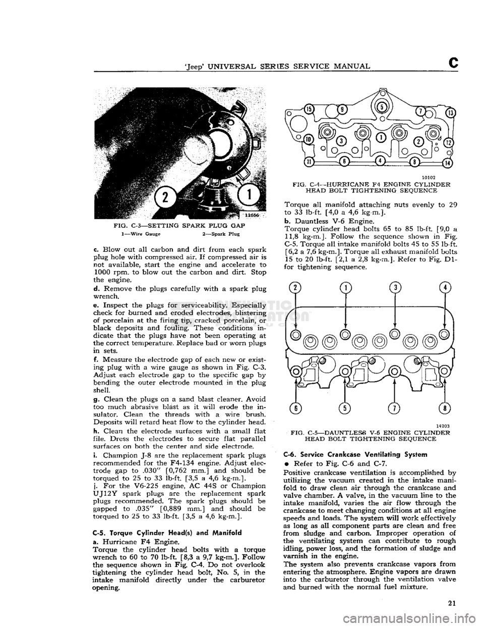
FIG.
C-3—SETTING SPARK PLUG
GAP
1—Wire
Gauge 2—Spark Plug
c.
Blow out all carbon and
dirt
from each
spark
plug hole with compressed air. If compressed air is
not available, start the engine and accelerate to 1000 rpm. to blow out the carbon and
dirt.
Stop
the engine.
d.
Remove the plugs carefully with a
spark
plug
wrench.
e. Inspect the plugs for serviceability. Especially
check
for burned and eroded electrodes, blistering
of porcelain at the firing tip, cracked porcelain, or
black
deposits and fouling. These conditions in
dicate that the plugs have not been operating at
the correct temperature. Replace bad or worn plugs
in
sets.
f. Measure the electrode gap of each new or exist
ing plug with a wire
gauge
as shown in Fig. C-3.
Adjust
each electrode gap to the specific gap by
bending the outer electrode mounted in the plug
shell.
g.
Clean
the plugs on a sand blast cleaner. Avoid
too much abrasive blast as it
will
erode the in
sulator.
Clean
the threads with a wire
brush.
Deposits
will
retard
heat flow to the cylinder head.
h.
Clean
the electrode surfaces with a small flat
file. Dress the electrodes to secure flat parallel surfaces on both the center and side electrode.
i.
Champion J-8 are the replacement
spark
plugs
recommended for the F4-134 engine. Adjust elec
trode gap to .030" [0,762 mm.] and should be
torqued to 25 to 33 lb-ft. [3,5 a 4,6 kg-m.].
j.
For the V6-225 engine, AC 44S or Champion
UJ12Y
spark
plugs are the replacement
spark
plugs recommended. The
spark
plugs should be gapped to .035" [0,889 mm.] and should be
torqued to 25 to 33 lb-ft. [3,5 a 4,6 kg-m.].
C-5. Torque Cylinder
Head(s)
and
Manifold
a.
Hurricane
F4 Engine.
Torque
the cylinder head bolts with a torque
wrench
to 60 to 70 lb-ft [8,3 a 9,7 kg-m.]. Follow
the sequence shown in Fig. C-4. Do not overlook
tightening the cylinder head bolt, No. 5, in the
intake
manifold directly under the carburetor
opening. 10102
FIG.
C-4—HURRICANE
F4
ENGINE CYLINDER HEAD BOLT TIGHTENING SEQUENCE
Torque
all manifold attaching nuts evenly to 29
to 33 lb-ft. [4,0 a 4,6 kg-m.].
b.
Dauntless V-6 Engine.
Torque
cylinder head bolts 65 to 85 lb-ft. [9,0 a 11,8 kg-m.]. Follow the sequence shown in Fig.
C-5.
Torque all intake manifold bolts 45 to 55 lb-ft. [6,2 a 7,6 kg-m.]. Torque all exhaust manifold bolts
15 to 20 lb-ft. [2,1 a 2,8 kg-m.]. Refer to Fig. Dl-
for tightening sequence. 14203
FIG.
C-5—DAUNTLESS
V-6
ENGINE CYLINDER HEAD BOLT TIGHTENING SEQUENCE C-6.
Service
Crankcase
Ventilating System
•
Refer to Fig. C-6 and C-7.
Positive crankcase ventilation is accomplished by
utilizing
the vacuum created in the intake mani
fold to draw clean air through the crankcase and
valve chamber. A valve, in the vacuum line to the
intake
manifold, varies the air flow through the
crankcase
to
meet
changing conditions at all engine
speeds
and loads. The system
will
work effectively as long as all component parts are clean and free
from
sludge and carbon. Improper operation of the ventilating system can contribute to rough
idling,
power loss, and the formation of sludge and
varnish
in the engine.
The
system also prevents crankcase vapors from
entering the atmosphere. Engine vapors are drawn
into the carburetor through the ventilation valve
and
burned with the normal fuel mixture. 21
Page 24 of 376
c
TUNE-UP
14011
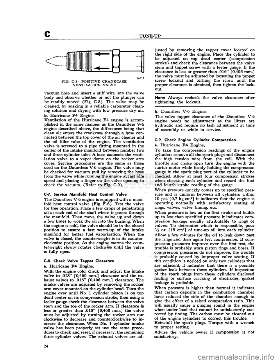
FIG.
C-8—POSITIVE CRANKCASE VENTILATION VALVE
vacuum
hose
and insert a stiff wire into the valve
body and observe whether or not the plunger can be readily moved (Fig. C-8). The valve may be
cleaned, by soaking in a reliable carburetor clean
ing solution and drying with low pressure dry air.
b.
Hurricane
F4 Engine.
Ventilation
of the
Hurricane
F4
engine
is accom
plished in the same manner as the Dauntless V-6
engine
described above, the differences being that clean air enters the crankcase through a
hose
con nected
between
the top cover of the air cleaner and
the oil filler tube of the engine. The ventilation valve is screwed to a pipe fitting mounted in the
center of the intake manifold
between
number two
and
three cylinder inlet. A
hose
connects the venti
lation valve to a vapor
dome
on the rocker arm
cover. Service procedures are the same as
those
used on the Dauntless V-6 engine. The valve may be checked for vacuum
pull
by removing the
hose
from
the valve while running the
engine
at fast idle speed and placing a finger on the valve opening to
check the vacuum. (Refer to Fig. C-9).
C-7.
Service
Manifold
Heat
Control
Valve
The
Dauntless V-6
engine
is equipped with a manifold heat control valve (Fig. F-6). Test the valve
for free operation. Place a few drops of penetrating
oil
at each end of the shaft where it passes through
the manifold.
Then
move
the valve up and down
a
few times to work the oil into the bushing. When
the
engine
is cold, the valve should be in the closed
position to ensure a fast warm-up of the intake
manifold for better fuel vaporization. When the
valve is closed, the counterweight is in its counter clockwise position. As the
engine
warms the coun
terweight slowly rotates clockwise until the valve is fully open.
C-8.
Check
Valve
Tappet
Clearance
a.
Hurricane
F4 Engine.
With
the
engine
cold, check and adjust the intake
valve to .018"
[0,460
mm.] clearance and the ex
haust valves to .016" [0,406 mm.] clearance. The
intake valves are adjusted by removing the rocker
arm
cover mounted on the cylinder head.
Turn
the
engine
over until No. 1 cylinder piston is on top
dead center on its compression stroke, then using a
feeler
gauge
check the clearance
between
the valve stem and the toe of the rocker arm. If clearance is
less
or greater than .018"
[0,460
mm.] the valve
must be adjusted by turning the rocker arm nut
clockwise to decrease and counterclockwise to in crease the clearance. When No. 1 cylinder intake
valve has been properly set use the same proce
dures to check and reset, if necessary, the remaining
three cylinder valves. The exhaust valves are ad justed by removing the tappet cover located on
the right side of the engine. Place the cylinder to
be adjusted on top dead center (compression stroke) and check the clearance
between
the valve stem and tappet screw with a feeler
gauge.
If the
clearance is
less
or greater than .016" [0,406 mm.]
the valve must be adjusted by loosening the tappet
screw locknut and turning the screw until the proper clearance is obtained, then tighten the lock-
nut.
Note:
Always recheck the valve clearance after
tightening the locknut.
b. Dauntless V-6 Engine.
The
valve tappet clearance of the Dauntless V-6
engine
needs
no adjustment as the lifters are
hydraulic
and require no lash adjustment at time
of assembly or while in service.
C-9.
Check
Engine
Cylinder
Compression
a.
Hurricane
F4 Engine.
To
take the compression readings of the
engine
cylinders
remove all the
spark
plugs and disconnect
the high tension wire from the coil.
With
the throttle and choke open
turn
the
engine
with the
starter
motor while firmly holding the compression
gauge
in the
spark
plug port of the cylinder to be
checked. Allow at least four compression strokes
when checking each cylinder and record the first
and
fourth stroke reading of the
gauge.
When
pressure quickly
comes
up to specified pres
sure
and is uniform
between
all cylinders within 10 psi. [0,7 kg-cm2] it indicates that the
engine
is
operating normally with satisfactory seating of
rings,
valves, valve timing, etc.
When
pressure is low on the first stroke and builds
up to
less
than specified pressure it indicates com
pression leakage usually attributable to rings or
valves. To determine which is responsible, pour
Vz
oz. [15 cm3] of tune-up oil into each cylinder.
Allow
a few minutes for the oil to leak down past
the rings and then again
test
compression. If com
pression pressures improve over the first
test,
the trouble is probably worn piston rings and bores. If
compression pressures do not improve, the trouble
is probably caused by improper valve seating. If
this condition is noticed on only two cylinders that
are adjacent, it indicates that there is a possible gasket leak
between
these
cylinders. If inspection
of the
spark
plugs from
these
cylinders disclosed
fouling or surface cracking of electrodes, gasket leakage is probable.
When
pressure is higher than normal it indicates
that carbon
deposits
in the combustion chamber have reduced the side of the chamber enough to
give
the
effect
of a raised compression ratio.
This
will
usually cause a pinging sound in the
engine
when under load that cannot be satisfactorily corrected by timing. The carbon must be cleaned out
of the
engine
cylinders to correct this trouble.
Reinstall
the
spark
plugs. Torque with a wrench
to proper setting.
Advise
the vehicle owner if compression is not satisfactory. 24
Page 35 of 376
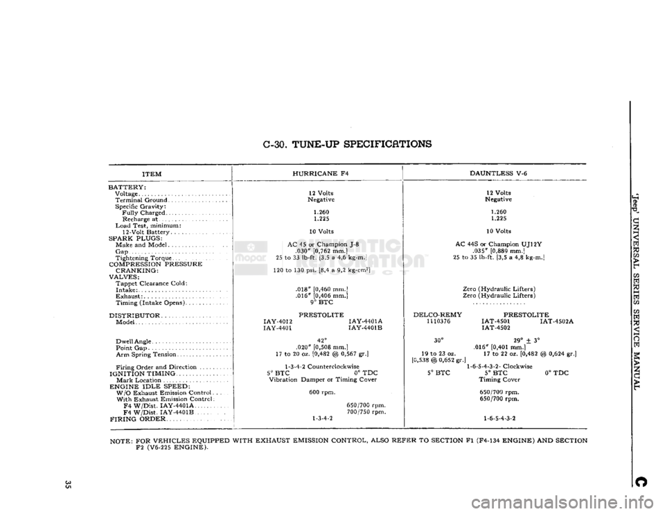
C-30.
TUNE-UP
SPECIFICATIONS
ITEM
BATTERY:
Voltage
Terminal
Ground Specific Gravity:
Fully
Charged Recharge at
Load
Test, minimum:
12-Volt Battery. .
SPARK PLUGS:
Make and Model
Gap
Tightening Torque
COMPRESSION
PRESSURE CRANKING:
VALVES:
Tappet Clearance Cold:
Intake
Exhaust:
Timing (Intake Opens)
DISTRIBUTOR
Model
Dwell
Angle
Point Gap
Arm
Spring Tension
Firing
Order and Direction ....
IGNITION TIMING.
Mark
Location
ENGINE
IDLE
SPEED: W/O
Exhaust Emission Control With Exhaust Emission Control
F4
W/Dist. IAY-4401A
F4
W/Dist. IAY-4401B
FIRING
ORDER HURRICANE
F4
DAUNTLESS
V-6
12 Volts
Negative
1.260 1.225
10 Volts
AC
45 or Champion J-8 .030"
[0,762
mm.]
25 to 33
lb-ft.
[3,5 a 4,6
kg-m.]
120 to 130 psi. [8,4 a 9,2
kg-cm2]
.018"
[0,460
mm.] .016"
[0,406
mm.]
9°
BTC
PRESTOLITE
IAY-4012
IAY-4401A
IAY-4401
IAY-4401B
42°
.020"
[0,508
mm.]
17 to 20 oz.
[0,482
@
0,567
gr.]
1-3-4-2
Counterclockwise
5° BTC
0° TDC
Vibration Damper or Timing Cover
600 rpm.
1-3-4-2
650/700
rpm.
700/750
rpm. 12 Volts
Negative
1.260 1.225
10 Volts
AC
44S or Champion UJ12Y .035"
[0,889
mm.]
25 to 35
lb-ft.
[3,5 a 4,8
kg-m.]
Zero (Hydraulic Lifters)
Zero (Hydraulic Lifters)
DELCO-REMY
1110376
PRESTOLITE
IAT-4501 IAT-4502A
IAT-4502
30°
19 to 23 oz.
[0,538
@
0,652
gr.'
5°
BTC
29°
± 3°
.016"
[0,401
mm.] 17 to 22 oz.
[0,482
1-6-5-4-3-2-
Clockwise
5°
BTC
Timing Cover
650/700
rpm.
650/700
rpm.
1-6-5-4-3-2
%
0,624
gr.]
0°
TDC
NOTE:
FOR
VEHICLES
EQUIPPED WITH EXHAUST
EMISSION
CONTROL, ALSO
REFER
TO
SECTION
Fl (F4-134
ENGINE)
AND
SECTION
F2
(V6-225
ENGINE).
Co O
Page 38 of 376
HURRICANE
F4
ENGINE
D-1.
GENERAL
This
section describes service and repair of the
F4
engine. The
engine
code
number shown in Fig.
A-3
is provided to identify the four cylinder engine.
The
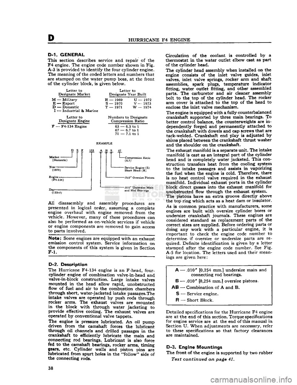
meaning of the coded letters and numbers that
are
stamped on the water pump boss, at the front of the cylinder block, is given below.
Letter
to
Designate
Market
M
—
Military
E
—
Export
D
— Domestic
I
—
Industrial
&
Marine
Letter
to
Designate
Engine
Letter
to
Designate
Year
Built
R
— 1969
S
— 1970
T
— 1971
U—
1972
V
— 1973
W
— 1974
Numbers
to Designate
Compression
Ratio
F
— F4-134
Engine
63
67
•
71
-
6.3 to 1
•
6.7 to 1
-
7.1 to 1
Market
-
D
S F
(Domestic)
(1970)
Engine-
EXAMPLE
123 A B S
(F4-134)
Day- "L
Compression
Ratio
(6.7)
-
Service Engine (S)
Short
Block
(R)
-.010*
Oversize Pistons
(123rd)
-.010*
Undersize
Main
and
Rod Bearings
All
disassembly and assembly procedures are
presented in logical order, assuming a complete
engine
overhaul with
engine
removed from the vehicle. However, many of
these
procedures can
also be performed as on-vehicle services if vehicle
or
engine
components are removed to gain access
to parts involved.
Note:
Some
engines
are equipped with an exhaust
emission control system. Service information on
the components of this system is given in Section
F-l.
D-2.
Description
The
Hurricane
F4-134
engine
is an F-head, four-
cyiinder
engine
of combination valve-in-head and valve-in-block construction.
Large
intake valves
mounted in the head allow
rapid,
unobstructed
flow of fuel and air to the combustion chambers through short, water-jacketed intake passages.The
intake valves are operated by push rods through
rocker
arms. The exhaust valves are mounted
in
the block with through water jacketing to provide
effective
cooling. The exhaust valves are
operated by conventional valve tappets.
The
engine
is pressure lubricated. An oil pump
driven
from the camshaft forces the lubricant
through oil channels and drilled passages in the
crankshaft
to efficiently lubricate the main and
connecting rod bearings.
Lubricant
is also force
fed to the camshaft bearings, rocker arms, timing
gears, etc.
Cylinder
walls and piston pins are
lubricated
from spurt
holes
in the "follow" side of
the connecting rods.
Circulation
of the coolant is controlled by a
thermostat in the water
outlet
elbow cast as part
of the cylinder head.
The
cylinder head assembly when installed on the
engine
consists of the inlet valve guides, inlet valves, inlet valve springs, rocker arm and shaft assemblies, spark plugs, temperature indicator
fitting, water
outlet
fitting, and other assembled
parts.
The carburetor and air cleaner assembly
bolt to the top of the cylinder head. The rocker
arm
cover is attached to the top of the head to
enclose
the inlet valve mechanism.
The
engine
is equipped with a fully counterbalanced
crankshaft
supported by three main bearings. To better control balance, the counterweights are in
dependently forged and permanently attached to
the crankshaft with dowels and cap screws that are tack-welded.
Crankshaft
end play is adjusted by
shims placed
between
the crankshaft thrust washer
and
the shoulder on the crankshaft.
The
exhaust manifold is a separate unit. The intake
manifold is cast as an integral part of the cylinder
head and is completely water jacketed.
This
con
struction transfers heat from the cooling system
to the intake passages and assists in vaporizing
the fuel when the
engine
is cold. Therefore, there
is no heat control valve required in the exhaust manifold. Individual exhaust ports in the cylinder
block direct
gasses
into the exhaust manifold for unobstructed flow through the exhaust system.
The
pistons have an extra
groove
directly above
the top ring which acts as a heat dam or insulator.
As
is common practice with manufacturers,
some
engines
are built with oversize cylinder bores or undersize crankshaft journals. These
engines
are
considered standard as replacement parts of the
correct
sizes are supplied. Before ordering parts or
doing any work with a particular engine, it is important to check the
engine
code
number to
determine if oversize or undersize parts are re
quired.
Definite identification is given by a letter
stamped after the
engine
code
number. See Fig.
A-5
for location. The letters used and their mean ings are given here:
A
— .010*
[0,254
mm.] undersize main and
connecting rod bearings.
B
— .010"
[0,254
mm.] oversize pistons.
AB
—
Combination
of A and B.
S
—
Service
engine.
R
—
Short
Block.
Detailed specifications for the
Hurricane
F4
engine
are
at the end of this section.
Torque
specifications
for
engine
service are at the end of this manual in Section U. When adjustments are necessary, refer to
these
specifications so that factory clearances
are
maintained.
D-3.
Engine Mountings
The
front of the
engine
is supported by two rubber
Text continued on
page
41. 38
Page 49 of 376
'Jeep'
UNIVERSAL SERIES
SERVICE
MANUAL
D
FIG.
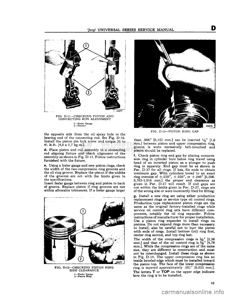
D-ll—CHECKING PISTON
AND
CONNECTING
ROD
ALIGNMENT 1—
Feeler
Gauge
2—
Fixture
the
opposite
side from the oil spray
hole
in the
bearing
end of the connecting rod. See Fig. D-10.
Install
the piston pin lock screw and torque 35 to
41 lb-ft. [4,8 a 5,7 kg-m.].
d.
Place piston and rod assembly in a connecting
rod
aligning fixture and check alignment of the
assembly as shown in
Fig. D-ll.
Follow instructions
furnished
with the fixture.
e. Using a feeler
gauge
and new piston rings, check the width of the two compression ring
grooves
and
the oil ring groove. Replace the piston if the widths of the
grooves
are not with the limits given in
the specifications.
Insert
feeler
gauge
between
ring and piston to back
of groove. Replace piston if ring
grooves
are not
within
allowable tolerances. If a feeler
gauge
larger
FIG.
D-l 2—CHECKING PISTON RING
SIDE
CLEARANCE
1—
Feeler
Gauge
2—
Piston
Ring
FIG.
D-13—PISTON
RING
GAP
than
.006" [0,152 mm.] can be inserted
J^6"
[1,6
mm.]
between
piston and upper compression
ring,
groove
is worn excessively bell-mouthed and
piston should be replaced.
f.
Check
piston ring end gap by placing compres sion ring in cylinder bore below ring travel using head of an inverted piston as a plunger to push
ring
in squarely. End gap must be as shown in
Par.
D-37 for all rings. If less, file ends to obtain
minimum
gap.
With
cylinders bored to an exact
ring
oversize of
+.020", +.030",
or
+.040"
[0,508-
0,762-1,016
mm.] the proper end clearance as given in Par. D-37
will
result. If end
gaps
are
not within the limits given in Par.
D-3
7, rings are
of the wrong size or were incorrectly filed for fitting.
g.
Install
a new ring set using either production replacement rings or service type oil control rings.
Production
type replacement piston rings are the
same as the original factory-installed rings while
service oil control ring
sets
have different com
ponents, notably the oil ring expander. Follow
instructions of
manufacturer
for proper installation.
Use
a piston ring expander to install rings on pistons. Do not expand rings more than necessary
to install, also be careful not to
burr
the piston
with
ends of rings.
Install
bottom
(oil) ring first, center ring second, and top ring last.
The
width of the compression rings is [2,38
mm.] and that of the oil control ring is f^" [4,78
mm.].
While the compression rings are of the same
size, they are different in construction and must
not be interchanged.
Install
these
rings as shown
in
Fig. D-14. The upper compression ring has an
inside beveled
edge
which must be installed toward
the piston top. The face of the lower compression
ring
is tapered approximately .001" [0,025 mm.].
The
letters T or TOP on the upper
edge
indicate
how the ring is to be installed. 49
Page 51 of 376
![JEEP CJ 1953 Service Manual
-Jeep*
UNIVERSAL
SERIES SERVICE
MANUAL
E>
[5,928 a
5,926
cm.] for all main bearings. Allowable
taper or out-of-round of the journals is .001"
[0,0254
mm.].
D-42.
Checking Connecting Ro JEEP CJ 1953 Service Manual
-Jeep*
UNIVERSAL
SERIES SERVICE
MANUAL
E>
[5,928 a
5,926
cm.] for all main bearings. Allowable
taper or out-of-round of the journals is .001"
[0,0254
mm.].
D-42.
Checking Connecting Ro](/img/16/57040/w960_57040-50.png)
-Jeep*
UNIVERSAL
SERIES SERVICE
MANUAL
E>
[5,928 a
5,926
cm.] for all main bearings. Allowable
taper or out-of-round of the journals is .001"
[0,0254
mm.].
D-42.
Checking Connecting Rod
Crankpins
Check
the crankpin diameters with a micrometer
to ensure that they are not out-of-round or tapered more than .001"
[0,0254
mm.] The standard
crank-
pin
diameter is
1.9383*
to
1.9375"
[4,9233
a
4,9213
cm.].
D-43.
Crankshaft
Main
Bearings
The
crankshaft rotates on three main bearings
with
a running clearance of .0003" to .0029"
[0,0076
a
0,0736
mm.].
These
bearings are positioned and prevented from
rotating in their supports in the cylinder block by
dowel pins. Dowel pins are used in both the center
and
the
rear
bearing caps. No dowel pins are used
in
the front bearing cap because the bearing has
a
flange. The front main bearing takes the end
thrust
of the crankshaft. The main bearings are of premium type which provides long bearing life.
They
are replaceable and when correctly installed, provide proper clearance without filing, boring,
scraping,
or shimming. Crankshaft bearings can
be removed from this
engine
only with the
engine
out of the vehicle. Crankshaft bearings must be replaced as a complete set of three bearings, each
bearing consisting of two halves.
Main
bearings
are
available in the standard size and the following
undersizes:
.001" [0,025mm.] .012" [0,305 mm.] .002" [0,051mm.] .020" [0,508 mm.] .010" [0,254mm.] .030" [0,762 mm.]
The
.001" and .002" undersize main bearings are
for use with standard size crankshafts having
slightly worn
journals.
The .010", .020", and .030" undersize bearings are for use with undersize
crankshafts
in
those
sizes. The .012" undersize
bearings are for use with .010" undersize
crank
shafts having slightly worn journals. Bearing sizes
are
rubber stamped on the reverse side of each
bearing half.
D-44. Crankshaft
Main
Bearing Inspection
The
crankshaft
journals
must be carefully inspected
as detailed previously in Par. D-41. Worn journals
will
require undersize bearings. Scored, flaked, or
worn
bearings must be replaced. Measure the main
bearing bores in the cylinder block using a
telescope
gauge
and micrometer. Measure the bores at right
angles to the split line and at 45° to the split line.
The
bores should not be over .001"
[0,0254
mm.]
out-of-round or .001" in taper from end to end.
Also,
the bores should not be more then .001"
oversize, considering the average diameter of the
bore.
D-45.
Fitting Crankshaft
Main
Bearings
Using
Plastigage
After
wiping and carefully inspecting the bearing bore, install the proper bearing. See that the oil
hole
in the bearing upper half registers properly
with
the oil
hole
in the block, and that the bearing
lock fits properly in the notch in the block.
Install
the crankshaft if replacing bearings with the
engine
out of the vehicle. The desired running fit (dif
ference
between
the diameter of the crankshaft
journal
and the inside diameter of the fitted bear ing) for a main bearing is .0003" to .0029"
[0,0076
a
0,0736
mm.]. With a dimension in
excess
of this
standard
running fit, a satisfactory bearing replacement cannot be made and it
will
be necessary to
regrind
the crankshaft.
Install
the bearing lower
half
and the bearing cap and draw the nuts down
equally and only slightly tight. Rotate the
crank
shaft by hand to be sure it turns freely without
drag.
Pull
the nuts tighter, first one then the other,
a
little at a time, intermittently rotating the
crank
shaft by hand until the recommended torque of
35 to 45 lb-ft. [4,8 a 6,2 kg-m.] is reached. If the
bearings are of the correct size, and lubricated with
light oil before installation, the crankshaft should
turn
freely in the bearings. If the crankshaft cannot
be turned, a larger bearing is
required.
If there is no binding or tightness, it is still necessary to check
clearance to guard against too
loose
a fit. Never file
either the bearing cap or the bearing to compensate
for too much clearance. Do not use shims under a
bearing cap or behind a bearing shell. Do not run a
new bearing half with a worn bearing half. The use
of "Plastigage" of the proper size to measure .001" [0,025 mm.] clearance is recommended for check
ing crankshaft main bearing clearance. The method
of checking clearance is as follows:
a.
Remove the bearing cap and carefully wipe
all
oil from the bearing and the
journal.
b.
Lay a piece of "Plastigage" y%" [3 mm.]
shorter than the width of the bearing across the
journal
(lengthwise of the crankshaft).
c.
Install
the bearing and cap and tighten first
one nut, then the other, a little at a time to the specified torque. As the bearing
tightens
down
around
the
journal,
the "Plastigage" flattens to a
width that indicates the bearing clearance.
d.
Remove the cap and measure the width of
the flattened "Plastigage," using the scale printed
on the
edge
of the envelope. The proper size "Plasti
gage"
will
accurately measure clearance down to .001".
e. If the flattened "Plastigage" tapers toward the middle, or toward the end, or both ends, there
is a difference in clearance, indicating a taper, a
low
spot,
or other irregularity of the bearing or
journal.
D-46.
Fitting Crankshaft
Main
Bearings
Using
Shim Stock
Thin
feeler or shim stock may be used instead of "Plastigage" to check bearing clearances. The
method is simple, but care must be taken to protect
the bearing metal surface from
injury
by too much pressure against the feeler stock,
a.
Cut a piece of .001" [0,025 mm.] thick, by Yl [12,7 mm.] wide, feeler stock }4" [3 mm.]
shorter than the width of the bearing. Coat this 51